INSTALLATION MANUAL - fleet-lohmann.defleet-lohmann.de/office/VSAT Installation Manual.pdf ·...
17
Transcript of INSTALLATION MANUAL - fleet-lohmann.defleet-lohmann.de/office/VSAT Installation Manual.pdf ·...

Page 1
CONTENTS
1. Antenna Pedestal ......................................................................................................................................................... 2
1.1. Preparation and Mounting ................................................................................................................................. 2
1.2. Antenna Mounting Pattern ................................................................................................................................ 2
2. Above Deck Equipment (ADE) ...................................................................................................................................... 3
2.1. Antenna Specification......................................................................................................................................... 4
2.2. Unpacking ........................................................................................................................................................... 5
2.3. Lifting & Positioning ........................................................................................................................................... 6
3. Below Deck Equipment (BDE) ...................................................................................................................................... 9
3.1. Wall Mounted Rack ............................................................................................................................................ 9
3.2. Gyro .................................................................................................................................................................. 10
3.3. UPS ................................................................................................................................................................... 11
4. Cabling To BDE ........................................................................................................................................................... 14
4.1. Antenna ............................................................................................................................................................ 15
4.2. Ship Network .................................................................................................................................................... 15
4.3. Gyro .................................................................................................................................................................. 16
4.4. Power Supply .................................................................................................................................................... 16
Page 2
1. ANTENNA PEDESTAL
1.1. PREPARATION AND MOUNTING
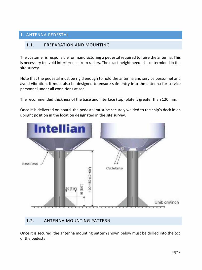
The customer is responsible for manufacturing a pedestal required to raise the antenna. This is necessary to avoid interference from radars. The exact height needed is determined in the site survey. Note that the pedestal must be rigid enough to hold the antenna and service personnel and avoid vibration. It must also be designed to ensure safe entry into the antenna for service personnel under all conditions at sea. The recommended thickness of the base and interface (top) plate is greater than 120 mm. Once it is delivered on board, the pedestal must be securely welded to the ship’s deck in an upright position in the location designated in the site survey.
1.2. ANTENNA MOUNTING PATTERN
Once it is secured, the antenna mounting pattern shown below must be drilled into the top of the pedestal.

Page 3
2. ABOVE DECK EQUIPMENT (ADE)

Page 4
2.1. ANTENNA SPECIFICATION
Physical size and weight:
Total height: 1490mm (59 inches)
Total width: 1330mm (52 inches)
Weight of antenna: 128 kg. (282 lbs.)
Reflector size: 103 cm / 41 inches
Power requirements:
Antenna: 110-230V AC (10A)
Environmental conditions:
Temperature: -25 degrees C to +55 degrees C
Humidity: 100 % Condensing
Wind: Withstand relative average wind speed up to 56 m/sec (125mph)
Antenna range of Motion:
Elevation: -20 to +115 degrees
Cross Level: +/- 37 degrees
Azimuth: Unlimited
Ship Motions:
Roll: +/-25 degrees, 6 sec periods
Pitch: +/-15 degrees, 6 sec periods
Yaw: +/-8 degrees, 6 sec periods
Turning rate: Up to 12 deg./sec and 5deg/sec/sec
Headway: Up to 50 knots
ADU motion: Recommended not to exceed tangential accelerations of +/-0,5G
Page 5
2.2. UNPACKING
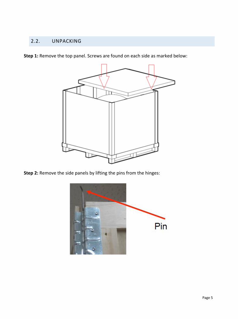
Step 1: Remove the top panel. Screws are found on each side as marked below:
Step 2: Remove the side panels by lifting the pins from the hinges:

Page 6
Step 3: Retrieve the ACU and installation kit boxes by unscrewing the securing brackets:
2.3. LIFTING & POSITIONING
Note that the antenna is initially ATTACHED to the base pallet.
Step 1: Secure the harness around the radome as shown using the shackles provided. Fasten
the protective covering over the shackle as the exposed metal may damage the radome:

Page 7
Step 2: Using a crane, lift the antenna and base and let it hover at shoulder level:
Page 8
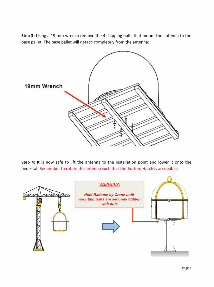
Step 3: Using a 19 mm wrench remove the 4 shipping bolts that mount the antenna to the
base pallet. The base pallet will detach completely from the antenna:
Step 4: It is now safe to lift the antenna to the installation point and lower it onto the
pedestal. Remember to rotate the antenna such that the Bottom Hatch is accessible:

Page 9
Step 5: Once lowered, secure the antenna to the pedestal as shown below. Use the supplied
bolts from the Installation Kit Box when securing the Radome. Apply Locktite #262 or
equivalent to the bolt thread, and fasten it to a torque setting of 110 N.m.
3. BELOW DECK EQUIPMENT (BDE)
3.1. WALL MOUNTED RACK
The 18U rack supplied by WINS containing the equipment must be mounted in the location
agreed upon in the Site Survey. The installation site must meet temperature, humidity and
vibrations requirements.
The rack can be floor or wall mounted. If the rack is floor mounted, it should be freely
accessible from the front and back sides for maintenance and service purposes.
The diagram below shows the exact rack dimensions, equipment normally found in the rack,
and the cabling to and from the rack. Further explanation regarding the cabling necessary
can be found in Section 4.

Page 10
FAN
PATCH PANEL
ACU
MODEM
ROUTER
SHELF + ATA
FREE
EPOWER
UPS
220 Volts
Ethernet to
Ship LAN
Rx
PowerTx
Gyro Cable from
Ship Gyro
80 cm
60 cm
FRONT VIEW
To VSAT ANTENNA
TOP VIEW
60 cm
60 cm
SIDE VIEW
60 cm
80 cm
3.2. GYRO
The WINS VSAT system requires the vessel’s heading. This is necessary to keep the antenna
pointing correctly at the satellite when the ship manoeuvres by counter rotating the antenna

Page 11
in the opposite direction. This is critical to maintaining a stable connection as this avoids
constantly loosing and re-acquiring the link.
A feed from the Gyro unit is hence necessary. A serial or Ethernet cable needs to be passed
from the gyro unit to the rack to accomplish this. If there isn’t a free port available gyro-side,
an NMEA switch or expander must be installed to increase the number of available ports.
3.3. UPS
WINS equipment is supplied from a high-performance UPS specially designed for marine
applications.
This UPS is mounted in the rack and the input ‘IN 230V’ shown below must be connected to
a suitable stable power supply protected by a residual current device.
A legend explaining the front status panel can also be found below to ensure that it is
operating in the correct mode.

Page 12

Page 13

4. CABLING TO BDE
Smart-UPS
3 0 0 0
TestI
O
AMERICAN POWER CONVERSION
Ship Power
NMEA-0183From Ship Gyro
Ship Router/FW
Internet Port
UPS 1700VAIntellian ACU
iDirect X5 modem
IP Managed Remote Power Switch
Below Deck Equipment (BDE)
Above Deck Equipment (ADE)
N
N
TX Cable
RX Cable
Cable RecommendationsBelow 50m : LMR 400Below 100m : LMR 600
Cisco 1812
Quintum VoIP Gateway2 x FXS
INTELLIAN V100 iDirect Setup
220 – 240 VAC
4.1. ANTENNA
A total of 3 cables need to be prepared for the VSAT antenna. All 3 cables will run from the
antenna to the rack.
For all three cables, kindly leave 2.5m extra at the antenna side.
Two of the cables are RF cables for the Tx and Rx channels. Depending on the length of cable
between the antenna and the rack, two possible cable types can be used. LMR 400 can be
used if the distance is less than 50m, whilst LMR 600 can be used if the distance is less than
100m.
This type of cable cannot be sharply bent or twisted. If it contains any kinks, it will not work!
Additionally, the end of the cable must not get wet. Do not leave it exposed in the rain!
The third cable is a power cable (3 core 2.5mm) used to power the antenna.
4.2. SHIP NETWORK
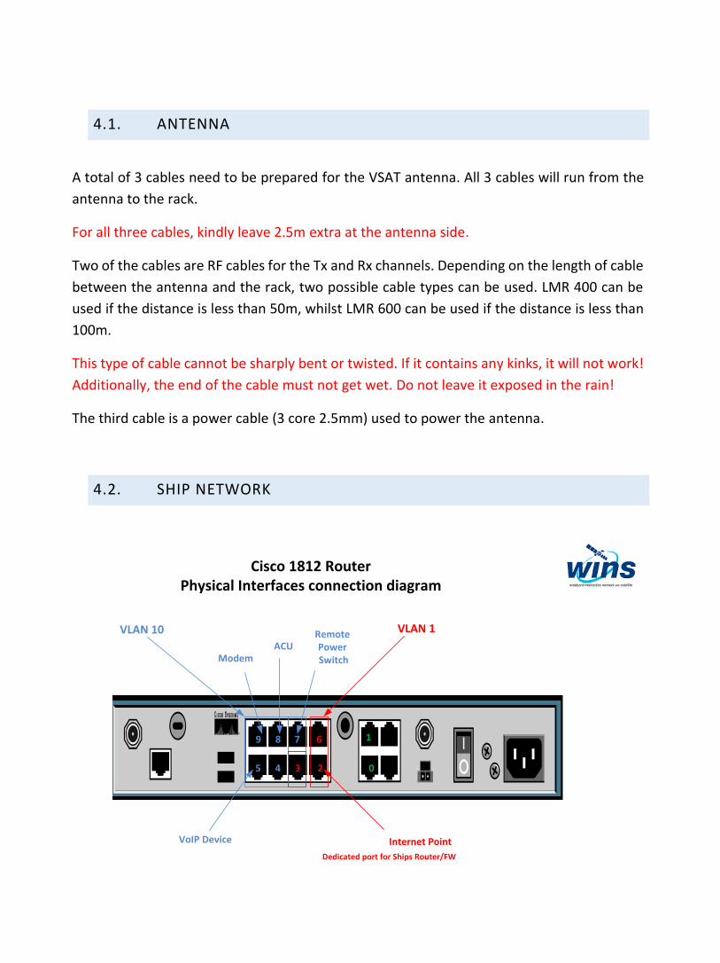
Cisco 1812 Router Physical Interfaces connection diagram
VLAN 10 VLAN 1
Internet Point
Dedicated port for Ships Router/FW
ModemACU
VoIP Device
Remote Power Switch
9 8 7 6
5 4 3 2
1
0

Page 16
In order to connect the ship’s existing internal network to the WINS system, a CAT6 patch
lead must be passed from the ship network router to the WINS router. On the WINS router,
the cable should be connected to Port 2.
4.3. GYRO
A serial or Ethernet cable needs to be passed from the gyro unit to the rack to obtain an
NMEA gyro reading. If there isn’t a free port available gyro-side, an NMEA switch or expander
must be installed to increase the number of available ports.
4.4. POWER SUPPLY
All the equipment in the rack is connected to the UPS via the ePower switch. To power up
the UPS itself, a power cable is included with the rack which is already plugged into UPS. This
cable needs to be connected to the closest distribution box available.
In case cable length is not enough, an additional 3 core 2.5mm power cables is provided with
rack. This needs to be laid from rack to power distribution box.