INSTALLATION MANUAL | FLAT TRACK SERIES Print 6.19...This manual covers the installation of the...
28
INSTALLATION MANUAL | FLAT TRACK SERIES
Transcript of INSTALLATION MANUAL | FLAT TRACK SERIES Print 6.19...This manual covers the installation of the...
INSTALLATION MANUAL | FLAT TRACK SERIES

I N T R O D U C T I O N
THANK YOU for purchasing Real Sliding Hardware. Our hardware will add a stunning accent to your living environment and maximize its space. It is made with the highest quality raw materials and finished by craftsmen in the USA. We are proud of our products and hope you enjoy how they enhance your world.
This manual covers the installation of the hardware for our flat track systems. It covers installation for seven different models. These include: Classic, Prop, Aero, Hammered, Horseshoe, Mini Classic, and Mini Aero. We always stand behind our product. If you have any questions during the installation process feel free to call, or email, us at:
Customer Service: 1-800-694-5977Email: [email protected]: www.realslidinghardware.com
2 Safety
3 Ledger Board
5 Soft Stop
6 Parts
Hardware
Tools Required
8 Structural Support
Check Top of Door Clearance
Check Door to Wall Clearance
12 Assembling the Door
13 Attaching Hangers
16 Mounting a Single Door
22 Mounting Bi-parting Doors
23 Bypass Bracket
23 Product Care
24 Warranty
C O N T E N T S
CO
NT
EN
T
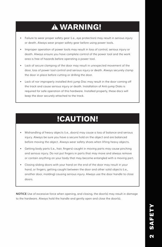
• Failure to wear proper safety gear (i.e., eye protection) may result in serious injury or death. Always wear proper safety gear before using power tools.
• Improper operation of power tools may result in loss of control, serious injury or death. Always ensure you have complete control of the power tool and the work area is free of hazards before operating a power tool.
• Lack of secure clamping of the door may result in unexpected movement of the door, loss of power tool control and serious injury or death. Always securely clamp the door in place before cutting or drilling the door.
• Lack of nor improperly installed Anti-jump Disc may result in the door coming off the track and cause serious injury or death. Installation of Anti-jump Disks is required for safe operation of this hardware. Installed properly, these discs will keep the door securely attached to the track.
• Mishandling of heavy objects (i.e., doors) may cause a loss of balance and serious injury. Always be sure you have a secure hold on the object and are balanced before moving the object. Always wear safety shoes when lifting heavy objects.
• Getting body parts (i.e., hair, fingers) caught in moving parts may cause pinching and serious injury. Do not put fingers in parts that may move and always remove or contain anything on your body that may become entangled with a moving part.
• Closing sliding doors with your hand on the end of the door may result in your hand, or fingers, getting caught between the door and other solid objects (i.e., another door, molding) causing serious injury. Always use the door handle to close
doors.
WARNING!
NOTICE Use of excessive force when opening, and closing, the door(s) may result in damage to the hardware. Always hold the handle and gently open and close the door(s).
!CAUTION!
2
SA
FE
TY

L E D G E R B O A R D
What is a Ledger Board?
Install your sliding hardware with ease by using our Ledger Board! Our Ledger Board is the fastest and easiest way to hang up our hardware. The board mounts securely to the wall with lock fasteners that screw directly into the studs, removing the need for support inside the wall.
Ledger Boards are available to pair with 4-18 ft. Classic, Aero, Prop, Mini, and Hammered Flat Track hardware and Hex Bar and Swiss Rod Architectural hardware. The Ledger Board is capable of carrying doors up to 400 lbs. with ease. You can even match your Ledger Board to your door’s wood species!
Each Ledger Board is shipped ready to install, complete with all the hardware needed for installation and easy-to-follow instructions. Boards are offered pre-drilled for your sliding hardware, or you may choose to have them not pre-drilled.
For all other Ledger Board lengths or special applications, please call us at (800) 694-5977 for pricing and availability.
3
LE
DG
ER
BO
AR
D

I N S T A L L A T I O N
Tools Needed:
• Pencil• Level• Power Drill• 1/4” Drill Bit
• Tape Measure• 5/6” Hex Driver• Stud Finder
1. Locate and make studs in your installation location.
2. Mark where you would like the door edge to be when the door is closed. Add 1.5” to that to find the board edge location.
3. Find your horizontal “drill line”. This can be figured by measuring your door height +2”. This will leave a 1/2” gap under the door, the drill line calculation can be adjusted accordingly.
4. From your board edge mark, measure to the center of each stud marked in step 2 and mark the corresponding location on your board along the center drill line. This keeps your mounting screws hidden behind your track.
5. Predrill your board at the stud locations with a ¼” drill bit.
6. Hold your board up on the wall, align the end marks, and drill line. Be sure to use a level to install the board. Sliding doors that are not level will only want to stay open or closed. Using your 5/16” driver, install your board with the provided screws. An impact driver or power drill works best for this.
7. You can now install your Real Sliding Hardware with the provided instructions.4
L
ED
GE
R B
OA
RD

U P G R A D E T O S O F T S T O P 2 . 0
No more slamming doors! This is the revolutionary new Soft Stop 2.0 system. Here to civilize your sliding barn door hardware and provide a clean, soft close. Inspired by the effortless movement seen in our range of Real Sliding Hardware products, the Soft Stop mechanism will gently and quietly assist your sliding door or barn door to its final open or closed position.
5
SO
FT
ST
OP
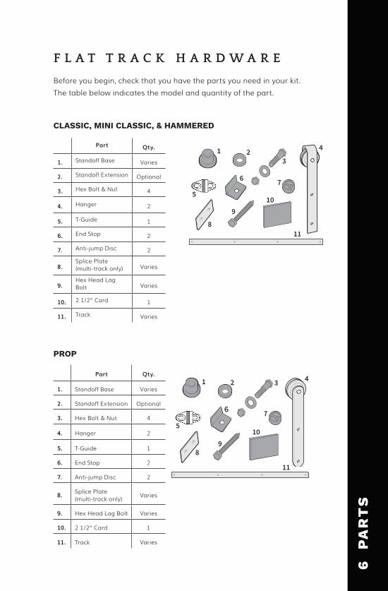
Before you begin, check that you have the parts you need in your kit. The table below indicates the model and quantity of the part.
F L A T T R A C K H A R D W A R E
CLASSIC, MINI CLASSIC, & HAMMERED
1 23
4
6
PROP
8
9 10
11
5
7
1 2 3 4
6
8 9
10
11
5
7
Part Qty.
1. Standoff Base Varies
2. Standoff Extension Optional
3. Hex Bolt & Nut 4
4. Hanger 2
5. T-Guide 1
6. End Stop 2
7. Anti-jump Disc 2
8.Splice Plate (multi-track only) Varies
9.Hex Head Lag Bolt Varies
10. 2 1/2” Card 1
11. Track Varies
Part Qty.
1. Standoff Base Varies
2. Standoff Extension Optional
3. Hex Bolt & Nut 4
4. Hanger 2
5. T-Guide 1
6. End Stop 2
7. Anti-jump Disc 2
8. Splice Plate (multi-track only) Varies
9. Hex Head Lag Bolt Varies
10. 2 1/2” Card 1
11. Track Varies
6
PA
RT
S

Note:
• Washer quantity varies with order.• Anti-crush Rings are optional. Call customer service to order.
AERO & MINI AERO
HORSESHOE
12
3
4
6
8 9
10
11
5 7
Part Qty.
1. Standoff Base Varies
2. Standoff Extension Optional
3. Hex Bolt & Nut 4
4. Hanger 2
5. T-Guide 1
6. End Stop 2
7. Anti-jump Disc 2
8.Splice Plate (multi-track only) Varies
9.Hex Head Lag Bolt Varies
10. 2 1/2” card 1
11. Track Varies
1 2 3
7 4 56
9 10
Part Qty.
1. Standoff Base Varies
2. Standoff Extension Optional
3. T-Guide 1
4. Hanger 2
5. End Stop 2
6. Anti-jump Disc 2
7. #14 Wood Screw 4
8. Hex Head Lag Bolt Varies
9. Splice Plate (multi-track only) Varies
10. Track Varies
8
7
PA
RT
S
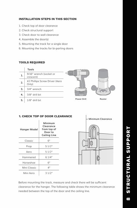
Before mounting the track, measure and check there will be sufficient clearance for the hanger. The following table shows the minimum clearance needed between the top of the door and the ceiling line.
Hanger Model
Minimum Clearance
from top of Door to
Ceiling Line
Classic 6”
Prop 5 1/2”
Aero 5 1/2”
Hammered 6 1/4”
Horseshoe 6”
Mini Classic 4”
Mini Aero 3 1/2”
1. Check top of door clearance2. Check structural support3. Check door to wall clearance4. Assemble the door(s)5. Mounting the track for a single door6. Mounting the tracks for bi-parting doors
Power Drill
Minimum Clearance 1. CHECK TOP OF DOOR CLEARANCE
TOOLS REQUIRED
INSTALLATION STEPS IN THIS SECTION
Tools
1. 9/16” wrench (socket or crescent)
2. #2 Phillips Screw Driver (Aero Only)
3. 3/4” wrench
4. 3/8” drill bit
5. 1/8” drill bit Router
8
ST
RU
CT
UR
AL
SU
PP
OR
T

If there is not adequate support (i.e., blocking or head casing) for the weight and movement of the door(s), then you must add structural support before attaching the track(s) and door(s) to the wall. Follow these steps to add structural support to an unfinished or finished wall.
Unfinished Wall
Blocking
1. Determine which direction you wish to open the door and add, or install structural support in that direction.
2. Check the length of the track(s) and determine the number of blocks you will need. Keep in mind the suggested door-to-frame overlap of 1” per side for doors up to 54” and 2” overlap per side for larger doors.
3. Cut the 2x6 block(s) to the correct length(s) between the wall studs.
4. Place the blocking at the appropriate height. Note: Add 2” to the height of the door, this is the ideal center of the block in.
5. Position the wide face of the blocking so it is flush with the front surface of the wall studs.
6. Securely fasten the blocking to the wall studs.
UNFINISHED WALL
2. CHECK STRUCTURAL SUPPORT
9
ST
RU
CT
UR
AL
SU
PP
OR
T
FINISHED WALL
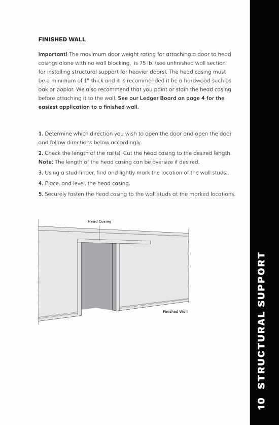
Important! The maximum door weight rating for attaching a door to head casings alone with no wall blocking, is 75 lb. (see unfinished wall section for installing structural support for heavier doors). The head casing must be a minimum of 1” thick and it is recommended it be a hardwood such as oak or poplar. We also recommend that you paint or stain the head casing before attaching it to the wall. See our Ledger Board on page 4 for the easiest application to a finished wall.
1. Determine which direction you wish to open the door and open the door and follow directions below accordingly.
2. Check the length of the rail(s). Cut the head casing to the desired length. Note: The length of the head casing can be oversize if desired.
3. Using a stud-finder, find and lightly mark the location of the wall studs..
4. Place, and level, the head casing.
5. Securely fasten the head casing to the wall studs at the marked locations.
Finished Wall
Head Casing
10
ST
RU
CT
UR
AL
SU
PP
OR
T
Wall Clearance
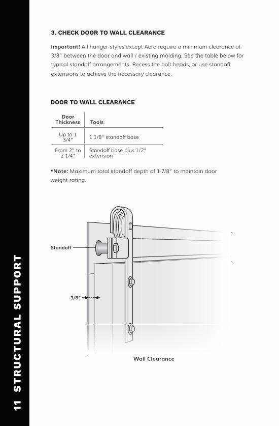
3. CHECK DOOR TO WALL CLEARANCE
Important! All hanger styles except Aero require a minimum clearance of 3/8” between the door and wall / existing molding. See the table below for typical standoff arrangements. Recess the bolt heads, or use standoff extensions to achieve the necessary clearance.
*Note: Maximum total standoff depth of 1-7/8” to maintain door weight rating.
Standoff
DOOR TO WALL CLEARANCE
Door Thickness Tools
Up to 1 3/4” 1 1/8” standoff base
From 2” to 2 1/4”
Standoff base plus 1/2” extension
3/8”
9
ST
RU
CT
UR
AL
SU
PP
OR
T11
S
TR
UC
TU
RA
L S
UP
PO
RT

Track Type Maximum Door Weight (lb)
Classic 400
Prop 150
Aero 150
Hammered 400
Horseshoe 550
Mini Classic 100
Mini Aero 100
DOOR WEIGHT RATINGS
Bottom guides keep the door from swinging in and out. There are three types of bottom guides, the T-Guide, C-Guide, and the Wall Mounted Stay Roller. Of the three guides, only the T-Guide requires door preparation. Follow these steps to cut the slot for the T-Guide:
1. Securely clamp the door.
2. Using a router with 1/4” slot cutter, cut a slot that is 5/16” wide by 1/2” deep. Several passes of the router will be necessary.
CUT THE T-GUIDE SLOT (T-GUIDES ONLY)
Wall Clearance
Cut 5/16” wide by 1/2” deep slot
4. ASSEMBLING THE DOOR
Important! The hardware is rated to handle a maximum door weight. Do not attach a door that exceeds the weight capacity of the hardware.
12
AS
SE
MB
LIN
G T
HE
DO
OR

(Does not include Aero) There are five types of hangers for the flat track system. All of them, except Aero, require mounting holes drilled through the door. For Classic, Prop, Hammered, and Horseshoe drill a 3/8th clearance hole into the side.
Important! Do not drill side mounting holes if you have Aero hardware. Classic, Prop, Hammered, and Horseshoe hangers are mounted on the front (outside face) of the door.
A T T A C H I N G T H E H A N G E R S
ATTACHING HANGERS TO THE DOOR
1. Place the hanger, with a 2 1/2” spacer (1 3/8” for mini) set into the groove of wheel, on top of the door. Note: You can use stiff cardboard if needed.
2. Position the hanger the desired distance in from the outside edge of the door. Note: Two (2”) inches is a recommended distance from the outside edge of the hanger and outside edge of the door for all hangers.
3. Place a square against the hanger and square the hanger to the door.
4. Mark the hole positions.
5. Setup your power tool with the correct drill bit.
6. From the face to the door, drill a pilot hole through the face of the door.
7. Drill the clearance hole.
8. Place the hanger over the mounting holes and square it to the door.
9. Insert the correct hex bolts and washers from the back of the door.
9
ST
RU
CT
UR
AL
SU
PP
OR
T13
A
TT
AC
HIN
G T
HE
HA
NG
ER
S
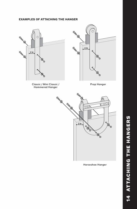
Classic / Mini Classic / Hammered Hanger
Prop Hanger
Horseshoe Hanger
EXAMPLES OF ATTACHING THE HANGER
2 in
2 in
2 in
14
AT
TA
CH
ING
TH
E H
AN
GE
RS

ATTACHING AERO & MINI AERO HANGERS
Aero hangers can be mounted on the top of the door (non-mortised) or recessed in a pocket (mortised). For aesthetic’s sake, it is recommended to mount Aero hangers in a recessed pocket. Note: If you choose to mount the hanger on top of the door without a pocket, then add 3/16” to the track mounting height.
Follow these steps to attach the hangers in a recessed pocket:
1. Determine the desired distance in from the outside edge of the door. Note: Two (2”) inches is a recommended distance from the outside edge of the hanger strap and outside edge of the door.
2. For regular Aero, layout and cut a pocket that is 1 1/8” wide and a minimum 4 1/2” long. Mini: cut a pocket that is 5/8” wide and 3” long.Note: You will need to cut, or chisel, clearance for the hanger strap.
3. After ensuring the hangers are aligned and level, drill diameter pilot holes for the screws.
4. Fasten the hanger to the door with the screws provided.
Note: Cut or chisel clearance for hanger strap.
4 1/2”1 1/8”
1/2”
2”
Hanger Strap
Screw
Aero InstallationAero Pocket Dimensions
Mini Aero Pocket Dimensions
9
ST
RU
CT
UR
AL
SU
PP
OR
T15
A
TT
AC
HIN
G T
HE
HA
NG
ER
S

Follow these steps to mount the track for a single door installation:
1. To locate the position of the first mounting hole on the track:
a. Mark where the closed position of the door will be and measure 1 1/8” in from this point.
b. Mark the location of the first mounting hole.
c. Calculate the distance from the floor to the track mounting holes. Mark the position for the first mounting hole.
d. Snap a level guide line as a guide for your remaining holes.
TRACK MOUNTING HOLE CALCULATION (FROM FLOOR)
5. MOUNTING A SINGLE DOOR
Track Type Guide Clearance
Door Height
Distance from top of door to mounting hole
Distance from floor to track
mounting hole
Classic, Prop, Aero, Hammered, Horseshoe 1/2” 1 1/2”+ + =
2. You can mount the track with, or without, Drywall Anti-crush Rings:
If you are mounting the track without Drywall Anti-crush Rings:
a. Pre-drill 1/8” diameter pilot hole for the first mounting hole.
b. Drill a 3/8” diameter hole for the first mounting bolt.
If you are mounting the track with Drywall Anti-crush Rings:
With proper blocking behind the drywall, you can mount the track(s) on top of the drywall or use Drywall Anti-crush Rings. Note: The optional Anti-crush Rings come in 1/2” and 5/8” thickness.
a. Use a 1 1/4” spade/paddle bit and drill a clean hole through the drywall until you reach the blocking.
b. Insert the Drywall Anti-crush Ring (sold separately).
c. Pre-drill 1/8” diameter pilot hole for the first mounting hole.
d. Drill a 3/8” diameter hole for the first mounting bolt.
16
MO
UN
TIN
G A
SIN
GL
E D
OO
R

Standoff Extension (if needed)
Standoff Base
Lag
Anti-crush Ring (optional)
Track
Drill hole with 1 1/4” spade/paddle bit
3. Hold the track to the wall. Loosely screw the track in place.
4. Level the track and mark the remaining mounting hole locations along your level line guide. Note: If multiple tracks (i.e., 10 ft., 12 ft., 14 ft. kits) are being installed for a single door, then you may use a Splice Plate to connect the tracks.
5. Repeat step 2 on the remaining mounting holes.
6. On the first mounting hole, remove the track. Place a Standoff (and extensions, lip pointing down into the standoff base, if using) behind the track and place an End Stop on the track. Note: Depending on your installation you may have a Fixed End Cap or an Adjustable End Cap.
If you are attaching a Fixed End Stop:
a. Place an End Stop over the mounting hole (with the cushion pad facing the center of the track).
b. Loosely screw the Lag Screw into the wall.
c. On the opposite end mounting hole, place a Standoff (and extensions, if using) behind the track and an End Stop on the front of the track.
d. Place a Standoff behind each of the remaining mounting holes and screw the track securely to the wall.
9
ST
RU
CT
UR
AL
SU
PP
OR
T17
M
OU
NT
ING
A S
ING
LE
DO
OR
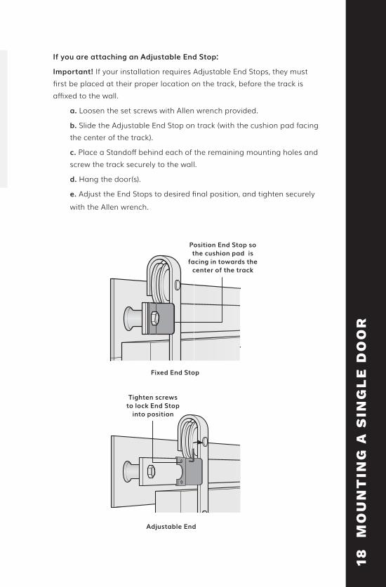
If you are attaching an Adjustable End Stop:
Important! If your installation requires Adjustable End Stops, they must first be placed at their proper location on the track, before the track is affixed to the wall.
a. Loosen the set screws with Allen wrench provided.
b. Slide the Adjustable End Stop on track (with the cushion pad facing the center of the track).
c. Place a Standoff behind each of the remaining mounting holes and screw the track securely to the wall.
d. Hang the door(s).
e. Adjust the End Stops to desired final position, and tighten securely with the Allen wrench.
Position End Stop so the cushion pad is
facing in towards the center of the track
Fixed End Stop
Adjustable End
Tighten screws to lock End Stop
into position
18
MO
UN
TIN
G A
SIN
GL
E D
OO
R
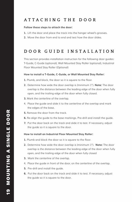
Follow these steps to attach the door:
1. Lift the door and place the track into the hanger wheel’s grooves.2. Move the door from end to end and test how the door slides.
A T T A C H I N G T H E D O O R
This section provides installation instruction for the following door guides: T-Guide, C-Guide (optional), Wall Mounted Stay Roller (optional), Industrial Floor Mounted Stay Roller (Optional)
D O O R G U I D E I N S T A L L A T I O N
How to install a T-Guide, C-Guide, or Wall Mounted Stay Roller:
1. Plumb, and block, the door so it is square to the floor.
2. Determine how wide the door overlap is (minimum 1”). Note: The door overlap is the distance between the leading edge of the door when fully open, and the trailing edge of the door when fully closed.
3. Mark the centerline of the overlap.
4. Place the guide and slide it to the centerline of the overlap and mark the edges of the base.
5. Remove the door from the track.
6. Re-align the guide to the base markings. Pre-drill and install the guide.
7. Put the door back on the track and slide it to test. If necessary, adjust the guide so it is square to the door.
How to install an Industrial Floor Mounted Stay Roller:
1. Plumb and block the door so it is square to the floor.
2. Determine how wide the door overlap is (minimum 1”). Note: The door overlap is the distance between the leading edge of the door when fully open, and the trailing edge of the door when fully closed
3. Mark the centerline of the overlap.
4. Place the guide in front of the door, on the centerline of the overlap.
5. Pre-drill and install the guide.
6. Put the door back on the track and slide it to test. If necessary, adjust the guide so it is square to the door.
9
ST
RU
CT
UR
AL
SU
PP
OR
T19
M
OU
NT
ING
A S
ING
LE
DO
OR

Installed T-Guide
Installed C-Guide
Installed Stay Roller
T-Guide
C-Guide
Stay Roller
20
M
OU
NT
ING
A S
ING
LE
DO
OR

WARNING! Lack of or improperly installed Anti-jump Disc may result in the door coming off the track and cause serious injury or death. Installation of Anti-jump Disks is required for safe operation of this hardware. Installed properly, these discs will keep the door securely attached to the track.
I N S T A L L A N T I - J U M P D I S C
Follow these steps to install the Anti-jump Disc on all models:
1. Locate the screw for the Anti-jump Disc 3/8” of an inch in from the front edge of the door, between the hanger and outside edge of the door.
2. Drill a pilot hole for the screw.
3. Place the Anti-jump Disc on the top of the door and screw in place.
4. Repeat steps 1 through 3 for the remaining hanger.
Installed Anti-jump Disc
Anti-jump Disc
3/8”
Screw
9
ST
RU
CT
UR
AL
SU
PP
OR
T2
1 M
OU
NT
ING
A S
ING
LE
DO
OR
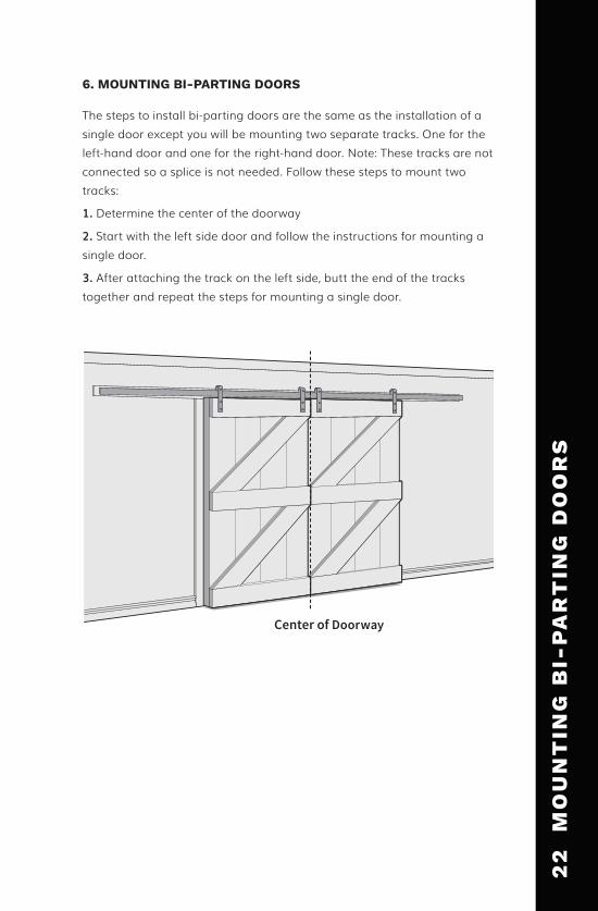
Center of Doorway
The steps to install bi-parting doors are the same as the installation of a single door except you will be mounting two separate tracks. One for the left-hand door and one for the right-hand door. Note: These tracks are not connected so a splice is not needed. Follow these steps to mount two tracks:
1. Determine the center of the doorway
2. Start with the left side door and follow the instructions for mounting a single door.
3. After attaching the track on the left side, butt the end of the tracks together and repeat the steps for mounting a single door.
6. MOUNTING BI-PARTING DOORS
22
M
OU
NT
ING
BI-
PA
RT
ING
DO
OR
S
9
ST
RU
CT
UR
AL
SU
PP
OR
T2
3
BY
PA
SS
BR
AC
KE
T
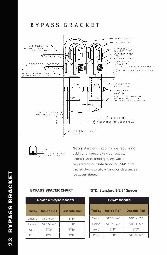
B Y P A S S B R A C K E T
BYPASS SPACER CHART
Trolley Inside Rail Outside Rail
Classic STD*+1/4” STD*
Horse STD*+1/4” STD*
Aero STD* STD*
Prop STD* STD*
1-3/8” & 1-3/4” DOORS 2-1/4” DOORS
Trolley Inside Rail Outside Rail
Classic STD*+1/4” STD*+1/2”
Horse STD*+1/4” STD*+1/2”
Aero STD* STD*
Prop STD* STD*+1/4”
*STD: Standard 1-1/8” Spacer
Notes: Aero and Prop trolleys require no additional spacers to clear bypass bracket. Additional spacers will be required on out-side track for 2-14” and thicker doors to allow for door clearances (between doors).
P R O D U C T C A R E
RAW STEEL
An attractive surface rust may develop on raw steel in humid environments. Surface rust does not affect the structural integrity of the hardware. If this appearance is not desired, remove rust deposits using a ScotchBrite™ pad and then apply wax, such as Johnson® Paste Finish Wax. After letting the wax sit, buff with a lint free cloth.
BRUSHED STAINLESS STEEL
• Use a Scotch-Brite™ pad to buff out minor scratches and imperfections.
• Periodically check the hardware for loose fasteners. Verify fasteners are secure.
• Keep the track and wheels free of dust and debris. Periodically wipe the track with a lint-free cloth dampened with water, a household stainless steel cleaner, or a silicone spray.
If damage to a powder coated finish occurs during installation, apply touch-up paint (not included, available for purchase).
POWDER COATED FINISHES
24
P
RO
DU
CT
CA
RE
*STD: Standard 1-1/8” Spacer
Hardware manufactured by Real Carriage Door & Sliding Hardware (hereafter referred to as “Real”) is warranted to be free from defects in material and workmanship under intended use for a period of 2 years from the date of purchase by the original owner. Finishes are not covered by this warranty. Hardware sold by Real but manufactured by others will be covered under the manufacturer’s warranty. If Real determines that any hardware is defective, Real will, at its option, repair or replace the defective part(s). Under no circumstances is Real liable for indirect or consequential damages of any kind. Real will not be liable, nor assume responsibility for damage or operational failures caused by supporting structures, surrounding structures, and/or equipment. Real is not liable if hardware is overloaded beyond the manufacturer’s rated capacity, or improperly used in an application beyond the manufacturer’s intended or recommended use, nor is Real liable for external causes such as abuse, or acts of Nature. Periodic maintenance and adjustments are the responsibility of the owner. Real will not cover maintenance and/or adjustments, or any services. Any hardware that has been modified voids all warranties. Real will assume no liability for any labor charges relative to the removal, or re-installation of any product.
REAL BARN DOOR KIT WARRANTY
Real Barn Door Kits (hereafter referred to as RBDK) manufactured by Real Carriage Door & Sliding Hardware (hereafter referred to as “Real”), are warranted to be free from defects in material and workmanship under intended use for a period of 1 year from the date of purchase by the original owner. Nicks, scratches, splinters, and rough spots are not considered defects and are inherent in a natural product. This warranty shall not extend or cover exterior uses of the RBDK. This warranty shall not extend or cover non-sliding applications of the RBDK. Finishes, whether applied by Real or the original owner are not covered in this warranty. The RBDK must be properly sealed on all sides with a high quality sealant or primer and finish paint within 7 days of receiving the kit. This warranty shall not extend to or cover any damages or claims for defects if the RBDK is not sealed and/or painted within the specified period of time. Should the RBDK be found defective as determined by Real or its representative(s), (e.g. warp-age, structural cracks, etc.), Real will replace or repair said part(s). Real will not be liable for applying a finish to replacement parts. Maintenance and adjustments are the responsibility of the owner, and Real will not reimburse for any maintenance services, nor will Real assume liability for any labor charges relative to the removal, or re-installation of replacement part(s). Any door that has been modified beyond its intended use voids all warranties.
REAL SLIDING HARDWARE WARRANTY
W A R R A N T Y
9
ST
RU
CT
UR
AL
SU
PP
OR
T2
5
WA
RR
AN
TY

NATURAL PRODUCT WARRANTY
As wood is a material with natural properties and inherent characteristics, the following are not considered defects: 1. Knots (filled or unfilled) in Rustic, Reclaimed or so-called “Knotty” wood doors, or doors over 2-1/4” in thickness.2. Natural color, texture, and density variances in any species3. Nicks, scratches, splinters, tight knots (smaller than a quarter), or “wooly” areas in some hardwoods.4. Superficial surface checks up to 3/64” in width
WARP WARRANTY
Definition: “Warp” refers to a variation within the plane of the door itself. Warp does not refer to the door in relation to the frame or jamb in which it is hung.Allowable Tolerance: Pursuant to WDMA I.S.6A, the allowable tolerance for 1-3/4” (and thicker) doors is 1/4” maximum in any 3’6” x 6’8” section.
Action on any claim for warp may be deferred for up to one year after project completion to permit doors to acclimate to temperature and humidity conditions. The deferral period does not count against the warranty period.
WARRANTY DESCRIPTION
Upon the purchase of a Real product, the buyer accepts this warranty and agrees it is the only official warranty, thereby excluding any other representation, warranty or condition, whether written or implied, offered by whomever, except if stated in writing by an authorized Real agent.
These warranties are subject to the following restrictions:The product has not been modified by or for the consumer by someone other than an authorized Real agent. The product has been used for its intended use under normal conditions, for individual residential use (excluding multiple residences or condominium). The product has been properly installed (This may require verification by an approved Real agent.)
Any claim must be submitted in writing to Real within thirty (30) days of discovery of the alleged defect and must be received by Real within the period of the warranty. Otherwise, the warranty shall not be honored.
These warranties expressly exclude:Any costs related to transporting the replacement product;Any installation and labor charges related to the replacement product;Any paint charges in the event the original door has been painted by or for the client;Any cost that the user of Real products may incur in exercising this warranty;Any cost resulting from an accident or any other in the event of defective materials.
26
W
AR
RA
NT
Y

O R D E R T O D A Y
To order please call us at 800.694.5977. Our experienced designers are ready to help you find the perfect doors and hardware for your project’s needs. Order your Real Carriage
doors and hardware today!
P 800.694.5977 F 253.857.9295
WWW.REALSLIDINGHARDWARE.COM
A B O U T U S
Real Carriage Door and Sliding Hardware is committed to excellence in creating high quality products for customers around the world. Built Real in the USA, our original door and hardware designs are visually stunning and structurally robust. We strive to exceed your expectations by combining personalized customer service with the highest quality products. We invite you to Build Real.™
Real is constantly releasing new, innovative, and exclusive products. We always have great things in the works, so swing by our website to stay completely up to date on everything we have to offer.
© 2016 Real Carriage Door Co. All rights reserved.
Real Carriage Door & Sliding Hardware9803 44th Ave NW Gig Harbor, WA 98332