INSTALLATION MANUAL - Aqua-Hot Installation... · Aqua-Hot 400-D Installation Manual ... Fuel...
56
INSTALLATION MANUAL © 2011 Aqua-Hot Heating Systems Inc.
Transcript of INSTALLATION MANUAL - Aqua-Hot Installation... · Aqua-Hot 400-D Installation Manual ... Fuel...
INSTALLATION MANUAL
© 2011 Aqua-Hot Heating Systems Inc.
CAUTION: The Aqua-Hot tank and heating loop operate at 0.0 psi (zero pressure system). Air pressure applied to the tank MUST NOT exceed 20 psi. Excess pressure will result in internal damage.
CAUTION: Before welding or plasma cutting on any coach; it is necessary to disconnect the electric wiring to the Aqua-Hot System. Failure to disconnect the wires from the Aqua-Hot System before using a welder or a plasma cutter on the coach may cause damage to the Aqua-Hot.
© 2011 Aqua-Hot® 400-D Installation Manual
TABLE OF CONTENTS
Aqua-Hot 400-D Installation Manual Introduction ........................................................................................................................................... 5 Section 1: Aqua-Hot Hydronic Heating System Technical Information .......................................................................................................................... 6
Section 2: Aqua-Hot Installation Installing the Mounting Tray and the Aqua-Hot .............................................................................. 10 Overall Aqua-Hot Dimensions ........................................................................................................... 11 Installing the Expansion Tank ............................................................................................................ 14
Section 3: Hydronic Heating System Heat Exchanger Location and Clearances ......................................................................................... 15 Heat Exchanger Mounting Requirements ......................................................................................... 15 Mounting the Heat Exchangers .......................................................................................................... 16 Sample Heating System Floorplan ...................................................................................................... 16 Wiring the Heat Exchangers ............................................................................................................... 19 Plumbing Requirements ....................................................................................................................... 22 Plumbing the Hydronic Heating System ........................................................................................... 22 Section 4: Thermostats Fresh Water Tank Thermostat ............................................................................................................ 25 Room Thermostats ............................................................................................................................... 26 Section 5: Domestic Water System Domestic Water System Requirements ............................................................................................. 27 Domestic Water System Plumbing ..................................................................................................... 27 Section 6: Switch Panel Switch Panel Location .......................................................................................................................... 29 Switch Panel Mounting ........................................................................................................................ 29 Switch Panel Wiring .............................................................................................................................. 29 Section 7: Fuel System Fuel Filter Location .............................................................................................................................. 31 Fuel System Requirements ................................................................................................................... 31 Fuel System Installation ....................................................................................................................... 31
Section 8: Exhaust System Exhaust System Requirements ............................................................................................................ 36 Installing the Exhaust System ............................................................................................................. 36 Section 9: Electronic Controller Wiring
Electronic Controller Wiring……………………………………………………………...40 Wiring Harness Connection………………………………………………………………41
Connecting the 12 Volt-DC Power……………………………………………………….42 Section 10 Purging the Systems Purging the Hydronic Heating System ............................................................................................... 43 Purging the System by Grounding the Zone Thermostat Connection ......................................... 44 Purging the Domestic Water System.................................................................................................. 44 Section 11: Initial Start-Up Activating the Aqua-Hot ...................................................................................................................... 46 Appendices: Appendix A: Wiring Diagram ............................................................................................................. 47 Appendix B: Wire Gauge Information .............................................................................................. 48 Appendix C: Electronic Controller Features .................................................................................... 49 Appendix D: Antifreeze Types ........................................................................................................... 51 Appendix E: Antifreeze Mixture Water Quality Recommendations ............................................. 51 Appendix F: Antifreeze Terms and Mixture Ratio .......................................................................... 52 Appendix G: Measuring Propylene Glycol Levels Using a Refractometer .................................. 54
TABLE OF CONTENTS (CONTINUED)
© 2011 Aqua-Hot® 400-D Installation Manual
INTRODUCTION
Danger, Warning, Caution, and Note Boxes:
Danger, Warning, Caution, and Note boxes appear throughout this manual as a means of alerting the installer to important information. INDICATES THAT PERSONAL INJURY IS LIKELY OR IMMI-
NENT. Indicates that serious damage to the heater will occur and personal injury is possible as well. Indicates that damage to the heater is possible. NOTE: Indicates information that requires special attention by
the installer.
— Page 5 —
CAUTION:
! DANGER !
WARNING
The Aqua-Hot 400D is a hydronic (water based) heating sys-tem, and a tank-less hot water system. The heating system provides moist, quiet, comfortable, interior heat with up to five separate, thermostatically-controlled tem-perature zones, and prevents tank and line freezing in the bays. The tank-less hot water system produces 75 gallons per hour of continuous, on-demand, hot water. This TribridHot™ designated system uses one or a combina-tion of heat sources to heat FDA-approved Generally Recog-nized as Safe (GRAS) propylene glycol based antifreeze solu-tion in the Aqua-Hot’s boiler tank. The 400D uses one 120 Volt-AC, 1650 Watt electric element to heat the system when shore power is available, and a 12 Volt-DC powered diesel burner provides heat when dry camping. The heat sources can be used separately or together.
New Low Emissions Technology virtually eliminates smoke and smell from the exhaust by reducing total hydrocarbon emission by 82% making Aqua-Hot the cleanest burning diesel powered hydronic system available.
Please note that all Danger, Warning, Caution, and Note boxes, appearing as needed throughout this manual, must be reviewed and adhered to during the installation procedure in order to avoid potential hazards, which could result in injury, death, product damage, or property damage. Should additional assistance be needed, please contact the Product Application Department at 1-800-685-4298, Monday through Friday, between the hours of 7:00 AM and 4:00 PM Mountain Time.
© 2011 Aqua-Hot® 400-D Installation Manual
SECTION 1: AQUA-HOT HYDRONIC HEATING SYSTEM
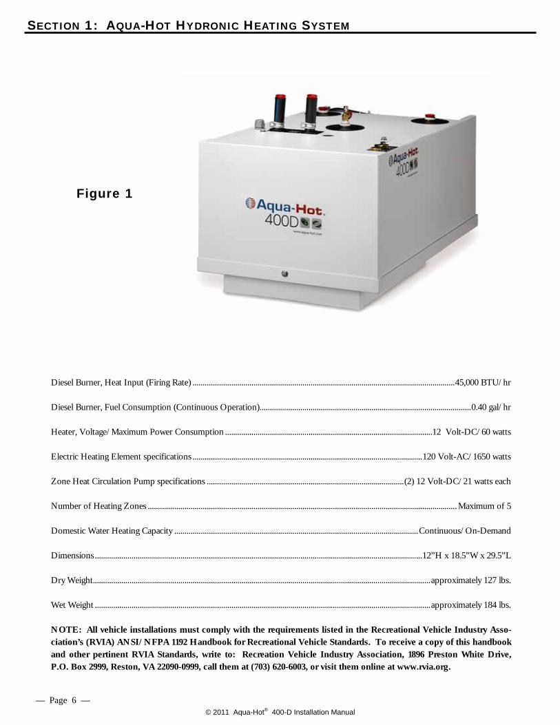
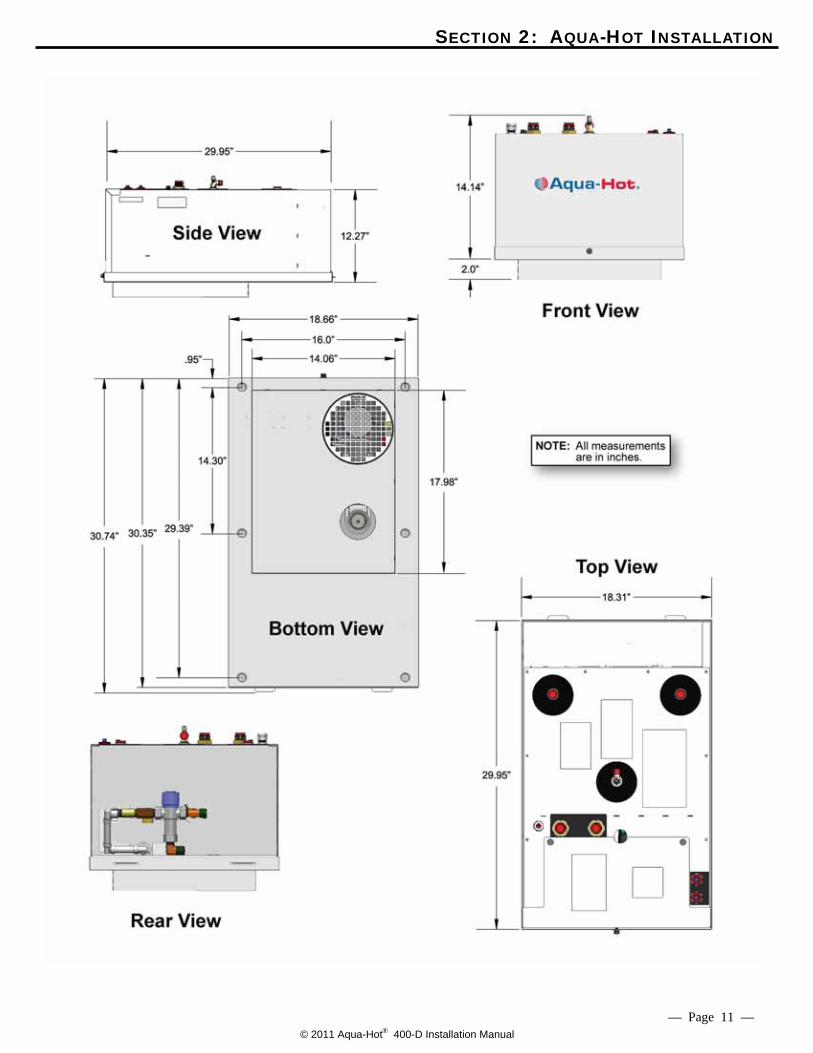
Diesel Burner, Heat Input (Firing Rate) ................................................................................................................................. 45,000 BTU/hr Diesel Burner, Fuel Consumption (Continuous Operation) ........................................................................................................ 0.40 gal/hr Heater, Voltage/Maximum Power Consumption ......................................................................................................12 Volt-DC/60 watts Electric Heating Element specifications ................................................................................................................. 120 Volt-AC/1650 watts Zone Heat Circulation Pump specifications ................................................................................................. (2) 12 Volt-DC/21 watts each Number of Heating Zones ........................................................................................................................................................ Maximum of 5 Domestic Water Heating Capacity ........................................................................................................................ Continuous/On-Demand Dimensions ................................................................................................................................................................. 12”H x 18.5”W x 29.5”L Dry Weight...................................................................................................................................................................... approximately 127 lbs. Wet Weight ..................................................................................................................................................................... approximately 184 lbs. NOTE: All vehicle installations must comply with the requirements listed in the Recreational Vehicle Industry Asso-ciation’s (RVIA) ANSI/NFPA 1192 Handbook for Recreational Vehicle Standards. To receive a copy of this handbook and other pertinent RVIA Standards, write to: Recreation Vehicle Industry Association, 1896 Preston White Drive, P.O. Box 2999, Reston, VA 22090-0999, call them at (703) 620-6003, or visit them online at www.rvia.org.
Figure 1
— Page 6 —
© 2011 Aqua-Hot® 400-D Installation Manual
SECTION 1: AQUA-HOT HYDRONIC HEATING SYSTEM
Each Aqua-Hot heating system possesses an I.D. label on the unit itself. This I.D. label details the specifications of the
heater, to what standard it has been tested, and important safety notices.
Figure 2
— Page 7 —
© 2011 Aqua-Hot® 400-D Installation Manual
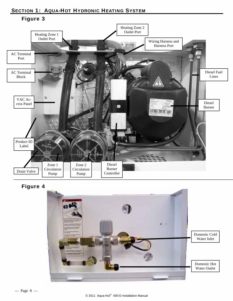
Figure 3
Wiring Harness and Harness Port
Diesel Fuel Lines
Drain Valve
AC Terminal Block
VAC Ac-cess Panel
AC Terminal Port
Diesel Burner
Heating Zone 1 Outlet Port
Heating Zone 2 Outlet Port
Product ID Label
Zone 1 Circulation
Pump
Zone 2 Circulation
Pump
Diesel Burner
Controller
Figure 4
Domestic Hot Water Outlet
Domestic Cold Water Inlet
SECTION 1: AQUA-HOT HYDRONIC HEATING SYSTEM
— Page 8 —
© 2011 Aqua-Hot® 400-D Installation Manual
SECTION 1: AQUA-HOT HYDRONIC HEATING SYSTEM
— Page 9 —
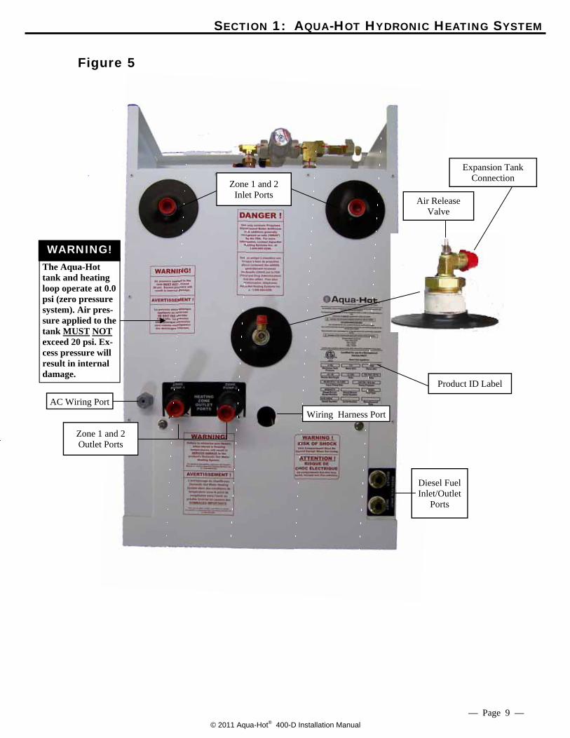
Figure 5
AC Wiring Port
Zone 1 and 2 Outlet Ports
Product ID Label
Diesel Fuel Inlet/Outlet
Ports
Zone 1 and 2 Inlet Ports Air Release
Valve
Expansion Tank Connection
Wiring Harness Port
WARNING! The Aqua-Hot tank and heating loop operate at 0.0 psi (zero pressure system). Air pres-sure applied to the tank MUST NOT exceed 20 psi. Ex-cess pressure will result in internal damage.
© 2011 Aqua-Hot® 400-D Installation Manual
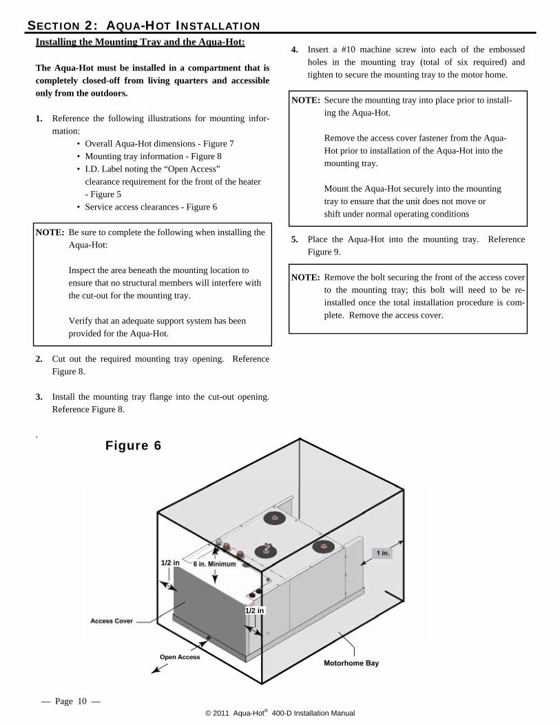
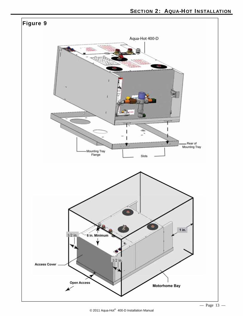
4. Insert a #10 machine screw into each of the embossed holes in the mounting tray (total of six required) and tighten to secure the mounting tray to the motor home.
NOTE: Secure the mounting tray into place prior to install-
ing the Aqua-Hot. Remove the access cover fastener from the Aqua- Hot prior to installation of the Aqua-Hot into the mounting tray. Mount the Aqua-Hot securely into the mounting tray to ensure that the unit does not move or shift under normal operating conditions
5. Place the Aqua-Hot into the mounting tray. Reference Figure 9.
NOTE: Remove the bolt securing the front of the access cover to the mounting tray; this bolt will need to be re-installed once the total installation procedure is com-plete. Remove the access cover.
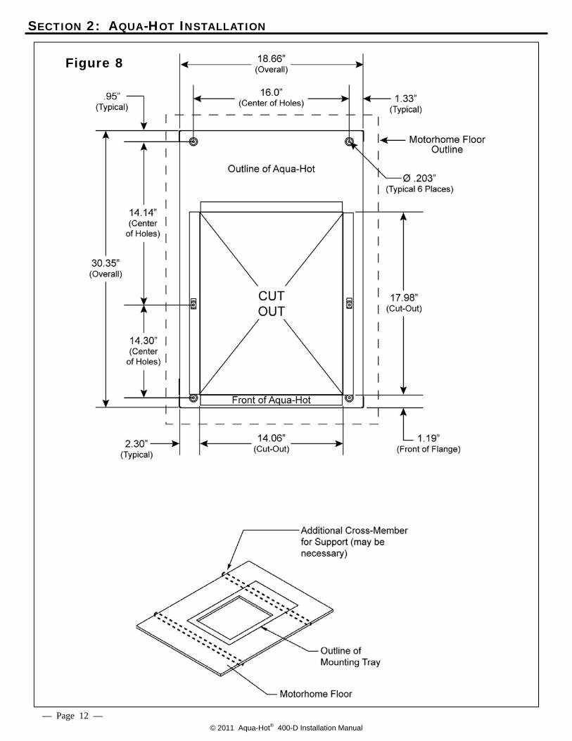
SECTION 2: AQUA-HOT INSTALLATION Installing the Mounting Tray and the Aqua-Hot:
The Aqua-Hot must be installed in a compartment that is completely closed-off from living quarters and accessible only from the outdoors.
1. Reference the following illustrations for mounting infor-
mation: • Overall Aqua-Hot dimensions - Figure 7 • Mounting tray information - Figure 8 • I.D. Label noting the “Open Access” clearance requirement for the front of the heater - Figure 5 • Service access clearances - Figure 6 NOTE: Be sure to complete the following when installing the
Aqua-Hot: Inspect the area beneath the mounting location to
ensure that no structural members will interfere with the cut-out for the mounting tray.
Verify that an adequate support system has been provided for the Aqua-Hot.
2. Cut out the required mounting tray opening. Reference
Figure 8. 3. Install the mounting tray flange into the cut-out opening.
Reference Figure 8.
. Figure 6
— Page 10 —
1/2 in
1/2 in
© 2011 Aqua-Hot® 400-D Installation Manual
SECTION 2: AQUA-HOT INSTALLATION
— Page 11 —
Figure 7
© 2011 Aqua-Hot® 400-D Installation Manual
SECTION 2: AQUA-HOT INSTALLATION
Figure 8
— Page 12 —
© 2011 Aqua-Hot® 400-D Installation Manual
SECTION 2: AQUA-HOT INSTALLATION
Figure 9
— Page 13 —
1/2 in.
1/2 in.
© 2011 Aqua-Hot® 400-D Installation Manual
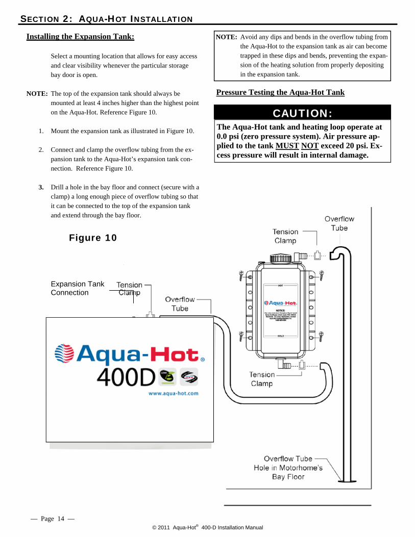
NOTE: Avoid any dips and bends in the overflow tubing from the Aqua-Hot to the expansion tank as air can become trapped in these dips and bends, preventing the expan-sion of the heating solution from properly depositing in the expansion tank.
SECTION 2: AQUA-HOT INSTALLATION
Figure 10
— Page 14 —
Expansion Tank Connection
Installing the Expansion Tank: Select a mounting location that allows for easy access
and clear visibility whenever the particular storage bay door is open.
NOTE: The top of the expansion tank should always be
mounted at least 4 inches higher than the highest point on the Aqua-Hot. Reference Figure 10.
1. Mount the expansion tank as illustrated in Figure 10. 2. Connect and clamp the overflow tubing from the ex-
pansion tank to the Aqua-Hot’s expansion tank con-nection. Reference Figure 10.
3. Drill a hole in the bay floor and connect (secure with a
clamp) a long enough piece of overflow tubing so that it can be connected to the top of the expansion tank and extend through the bay floor.
CAUTION: The Aqua-Hot tank and heating loop operate at 0.0 psi (zero pressure system). Air pressure ap-plied to the tank MUST NOT exceed 20 psi. Ex-cess pressure will result in internal damage.
Pressure Testing the Aqua-Hot Tank
© 2011 Aqua-Hot® 400-D Installation Manual
SECTION 3: HYDRONIC HEATING SYSTEM
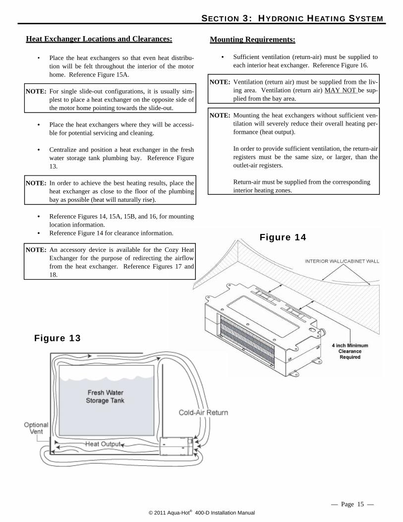
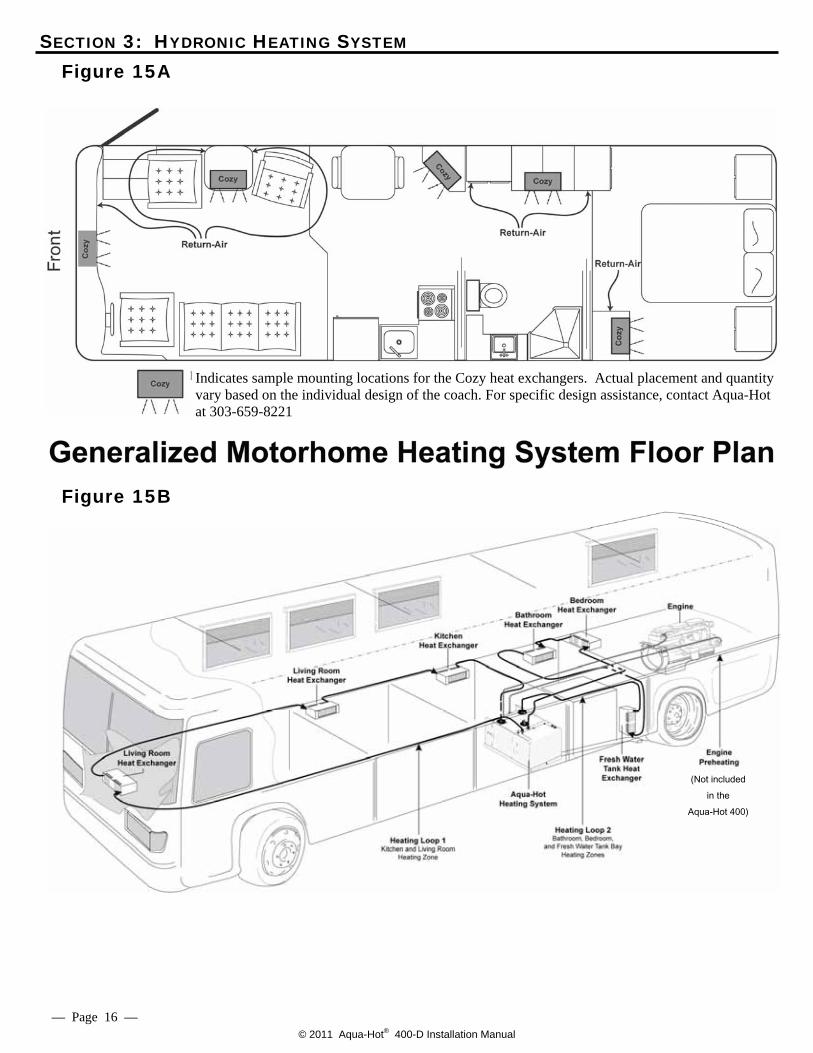
Heat Exchanger Locations and Clearances: • Place the heat exchangers so that even heat distribu-
tion will be felt throughout the interior of the motor home. Reference Figure 15A.
NOTE: For single slide-out configurations, it is usually sim-
plest to place a heat exchanger on the opposite side of the motor home pointing towards the slide-out.
• Place the heat exchangers where they will be accessi-
ble for potential servicing and cleaning. • Centralize and position a heat exchanger in the fresh
water storage tank plumbing bay. Reference Figure 13.
NOTE: In order to achieve the best heating results, place the
heat exchanger as close to the floor of the plumbing bay as possible (heat will naturally rise).
• Reference Figures 14, 15A, 15B, and 16, for mounting
location information. • Reference Figure 14 for clearance information.
NOTE: An accessory device is available for the Cozy Heat Exchanger for the purpose of redirecting the airflow from the heat exchanger. Reference Figures 17 and 18.
Mounting Requirements: • Sufficient ventilation (return-air) must be supplied to
each interior heat exchanger. Reference Figure 16.
NOTE: Ventilation (return air) must be supplied from the liv-ing area. Ventilation (return air) MAY NOT be sup-plied from the bay area.
NOTE: Mounting the heat exchangers without sufficient ven-
tilation will severely reduce their overall heating per-formance (heat output).
In order to provide sufficient ventilation, the return-air
registers must be the same size, or larger, than the outlet-air registers.
Return-air must be supplied from the corresponding
interior heating zones.
Figure 13
Figure 14
— Page 15 —
© 2011 Aqua-Hot® 400-D Installation Manual
Figure 15A
Figure 15B
Indicates sample mounting locations for the Cozy heat exchangers. Actual placement and quantity vary based on the individual design of the coach. For specific design assistance, contact Aqua-Hot at 303-659-8221
— Page 16 —
SECTION 3: HYDRONIC HEATING SYSTEM
(Not included in the
Aqua-Hot 400)
© 2011 Aqua-Hot® 400-D Installation Manual
SECTION 3: HYDRONIC HEATING SYSTEM
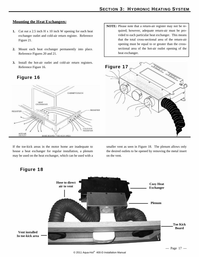
Mounting the Heat Exchangers:
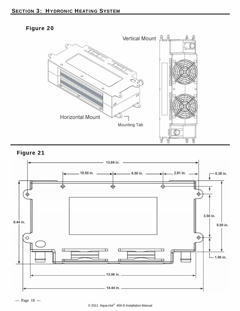
1. Cut out a 2.5 inch H x 10 inch W opening for each heat exchanger outlet and cold-air return register. Reference Figure 21.
2. Mount each heat exchanger permanently into place.
Reference Figures 20 and 21. 3. Install the hot-air outlet and cold-air return registers.
Reference Figure 16.
NOTE: Please note that a return-air register may not be re-
quired; however, adequate return-air must be pro-vided to each particular heat exchanger. This means that the total cross-sectional area of the return-air opening must be equal to or greater than the cross-sectional area of the hot-air outlet opening of the heat exchanger.
If the toe-kick areas in the motor home are inadequate to house a heat exchanger for regular installation, a plenum may be used on the heat exchanger, which can be used with a
smaller vent as seen in Figure 18. The plenum allows only the desired outlets to be opened by removing the metal insert on the vent.
Figure 16
Figure 17
Figure 18
— Page 17 —
Vent installed In toe-kick area
Cozy Heat Exchanger
Hose to direct air to vent
Toe Kick Board
Plenum
© 2011 Aqua-Hot® 400-D Installation Manual
SECTION 3: HYDRONIC HEATING SYSTEM
Figure 21
— Page 18 —
Figure 20
© 2011 Aqua-Hot® 400-D Installation Manual
SECTION 3: HYDRONIC HEATING SYSTEM
Figure 22
— Page 19 —
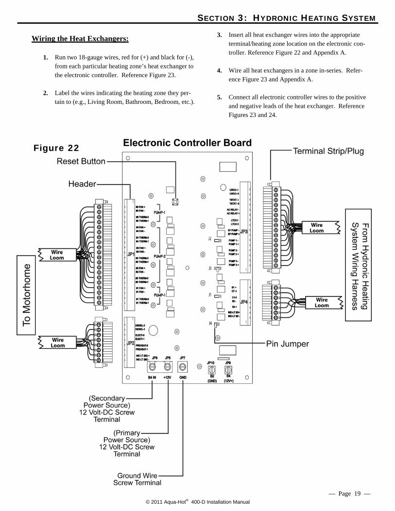
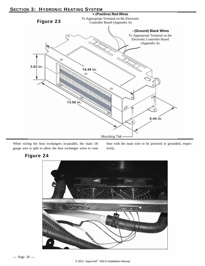
Wiring the Heat Exchangers: 1. Run two 18-gauge wires, red for (+) and black for (-),
from each particular heating zone’s heat exchanger to the electronic controller. Reference Figure 23.
2. Label the wires indicating the heating zone they per-
tain to (e.g., Living Room, Bathroom, Bedroom, etc.).
3. Insert all heat exchanger wires into the appropriate terminal/heating zone location on the electronic con-troller. Reference Figure 22 and Appendix A.
4. Wire all heat exchangers in a zone in-series. Refer-
ence Figure 23 and Appendix A. 5. Connect all electronic controller wires to the positive
and negative leads of the heat exchanger. Reference Figures 23 and 24.
© 2011 Aqua-Hot® 400-D Installation Manual
SECTION 3: HYDRONIC HEATING SYSTEM
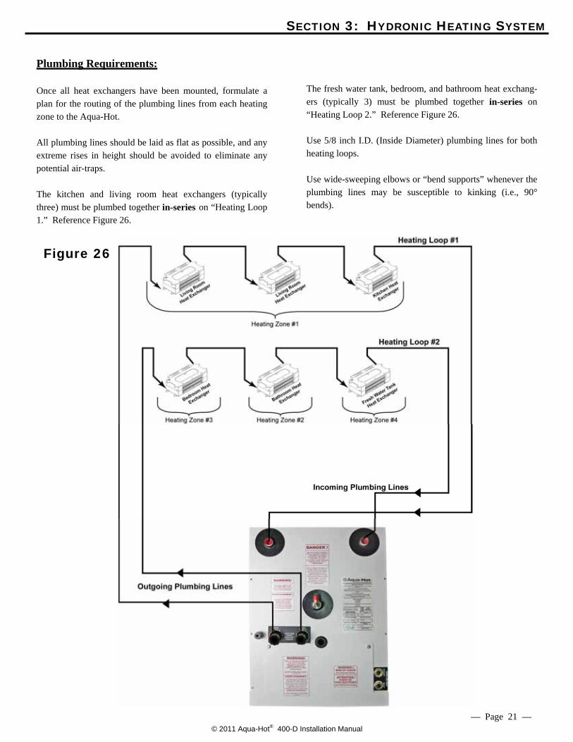
When wiring the heat exchangers in-parallel, the main 18-gauge wire is split to allow the heat exchanger wires to com-
bine with the main wire to be powered or grounded, respec-tively.
Figure 22
Figure 24
— Page 20 —
Figure 23
To Appropriate Terminal on the Electronic Controller Board
(Appendix A)
To Appropriate Terminal on the Electronic Controller Board (Appendix A)
© 2011 Aqua-Hot® 400-D Installation Manual
SECTION 3: HYDRONIC HEATING SYSTEM
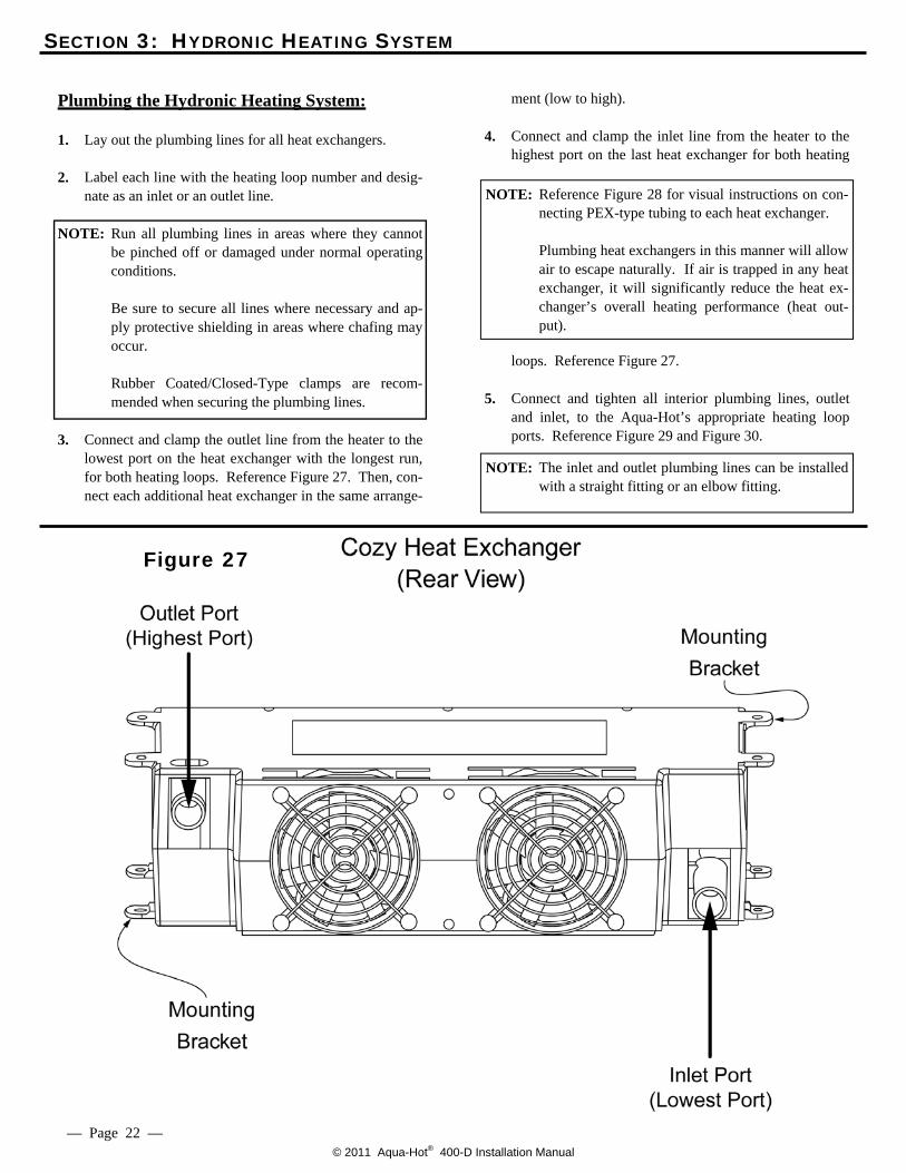
Plumbing Requirements: Once all heat exchangers have been mounted, formulate a plan for the routing of the plumbing lines from each heating zone to the Aqua-Hot. All plumbing lines should be laid as flat as possible, and any extreme rises in height should be avoided to eliminate any potential air-traps. The kitchen and living room heat exchangers (typically three) must be plumbed together in-series on “Heating Loop 1.” Reference Figure 26.
The fresh water tank, bedroom, and bathroom heat exchang-ers (typically 3) must be plumbed together in-series on “Heating Loop 2.” Reference Figure 26. Use 5/8 inch I.D. (Inside Diameter) plumbing lines for both heating loops. Use wide-sweeping elbows or “bend supports” whenever the plumbing lines may be susceptible to kinking (i.e., 90° bends).
Figure 26
— Page 21 —
© 2011 Aqua-Hot® 400-D Installation Manual
SECTION 3: HYDRONIC HEATING SYSTEM
Plumbing the Hydronic Heating System:
1. Lay out the plumbing lines for all heat exchangers. 2. Label each line with the heating loop number and desig-
nate as an inlet or an outlet line.
NOTE: Run all plumbing lines in areas where they cannot be pinched off or damaged under normal operating conditions.
Be sure to secure all lines where necessary and ap-
ply protective shielding in areas where chafing may occur.
Rubber Coated/Closed-Type clamps are recom-
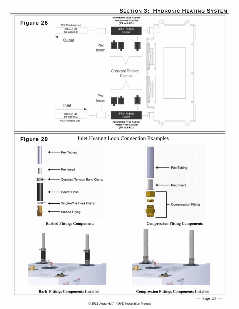
mended when securing the plumbing lines. 3. Connect and clamp the outlet line from the heater to the
lowest port on the heat exchanger with the longest run, for both heating loops. Reference Figure 27. Then, con-nect each additional heat exchanger in the same arrange-
ment (low to high).
4. Connect and clamp the inlet line from the heater to the highest port on the last heat exchanger for both heating
loops. Reference Figure 27.
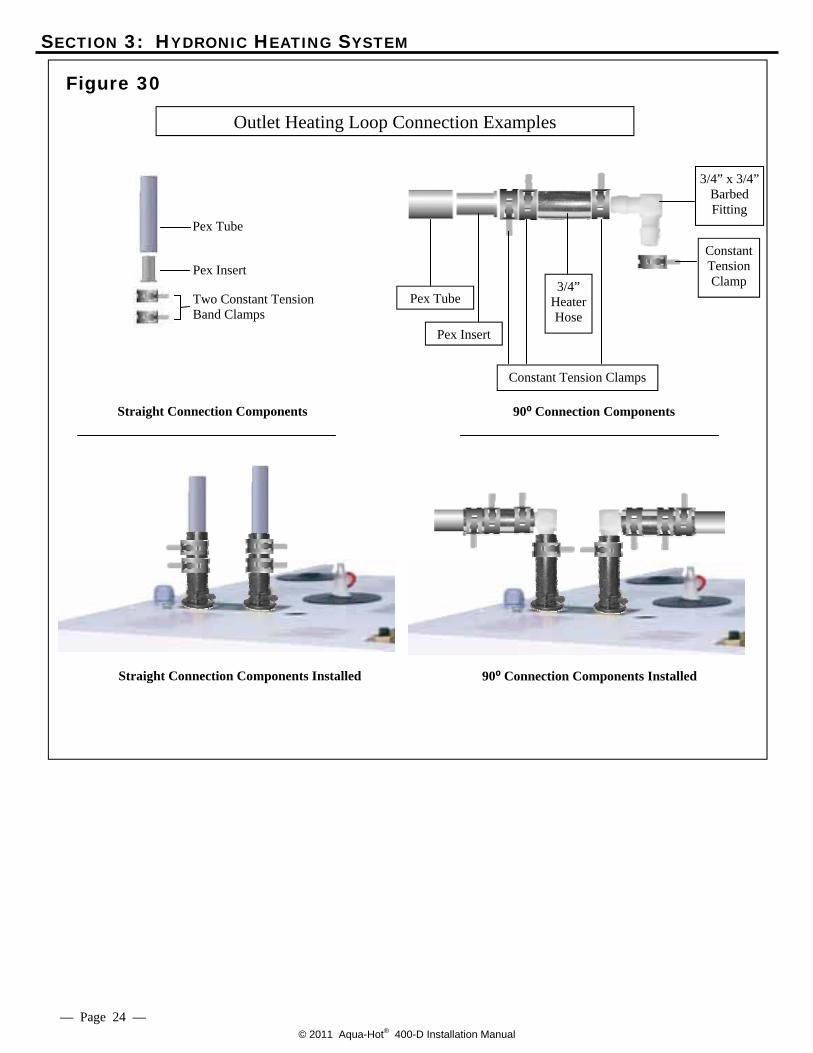
5. Connect and tighten all interior plumbing lines, outlet and inlet, to the Aqua-Hot’s appropriate heating loop ports. Reference Figure 29 and Figure 30.
Figure 27
— Page 22 —
NOTE: The inlet and outlet plumbing lines can be installed with a straight fitting or an elbow fitting.
NOTE: Reference Figure 28 for visual instructions on con-necting PEX-type tubing to each heat exchanger.
Plumbing heat exchangers in this manner will allow
air to escape naturally. If air is trapped in any heat exchanger, it will significantly reduce the heat ex-changer’s overall heating performance (heat out-put).
© 2011 Aqua-Hot® 400-D Installation Manual
SECTION 3: HYDRONIC HEATING SYSTEM
Figure 28
Figure 29
— Page 23 —
Barbed Fittings Components Compression Fitting Components
Inlet Heating Loop Connection Examples
Compression Fittings Components Installed
Barb Fittings Components Installed
© 2011 Aqua-Hot® 400-D Installation Manual
Figure 30
— Page 24 —
Outlet Heating Loop Connection Examples
SECTION 3: HYDRONIC HEATING SYSTEM
Straight Connection Components 90⁰ Connection Components
Pex Tube
Pex Insert
Two Constant Tension Band Clamps
Pex Tube
Pex Insert
Constant Tension Clamps
3/4” Heater Hose
Constant Tension Clamp
3/4” x 3/4” Barbed Fitting
90⁰ Connection Components Installed Straight Connection Components Installed
© 2011 Aqua-Hot® 400-D Installation Manual
SECTION 4: THERMOSTATS
Fresh Water Tank Thermostat Locations:
Select a location that will ensure even-heat distribution throughout the fresh water storage tank bay compartment in order to prevent the domestic water and plumbing system from freezing. Typically only the bulb of the thermostat needs to be physi-cally mounted in the area requiring heat (usually in close proximity to the domestic water pump). Reference Figure 31. Do not mount the thermostat bulb in a drafty area or along the ceiling of the bay. The selected mounting location should allow for easy opera-tor access and should be as low in the bay area as possible. Avoid mounting the fresh water tank thermostat’s bulb too close to the bay heat exchanger. Fresh Water Tank Thermostat Mounting:
1. Select a location for the thermostat bulb in the fresh wa-
ter storage tank bay compartment.
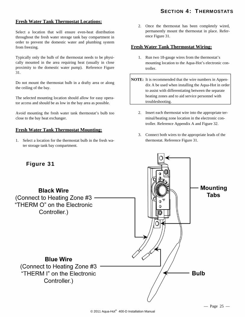
2. Once the thermostat has been completely wired,
permanently mount the thermostat in place. Refer-ence Figure 31.
Fresh Water Tank Thermostat Wiring:
1. Run two 18-gauge wires from the thermostat’s
mounting location to the Aqua-Hot’s electronic con-troller.
NOTE: It is recommended that the wire numbers in Appen-
dix A be used when installing the Aqua-Hot in order to assist with differentiating between the separate heating zones and to aid service personnel with troubleshooting.
2. Insert each thermostat wire into the appropriate ter-
minal/heating zone location in the electronic con-troller. Reference Appendix A and Figure 32.
3. Connect both wires to the appropriate leads of the
thermostat. Reference Figure 31.
Figure 31
— Page 25 —
© 2011 Aqua-Hot® 400-D Installation Manual
SECTION 4: THERMOSTATS
Room Thermostat Locations:
Select a location that will ensure even-heat throughout each heat-ing zone. Locate each thermostat at approximately chest level, if applicable.
NOTE: The selected location should prevent the thermostat from
being affected by: • drafts or dead spots behind doors and in corners • hot or cold air from ducts • radiant heat from the sun or appliances • heat from concealed pipes and chimneys • unheated or uncooled areas such as an outside
wall behind the thermostat
Room Thermostat Mounting:
Once the room thermostat has been wired, permanently mount the thermostat in place.
Be sure to then turn OFF both interior room thermostats.
Room Thermostat Wiring: 11. Run two 18 gauge wires from each room thermostat
mounting location to the Aqua-Hot’s electronic con-troller. Reference Appendix A.
NOTE: It is recommended that the wire numbers in Appendix
A be used when installing the Aqua-Hot in order to assist with differentiating between the separate heat-ing zones and to aid service personnel with trouble-shooting.
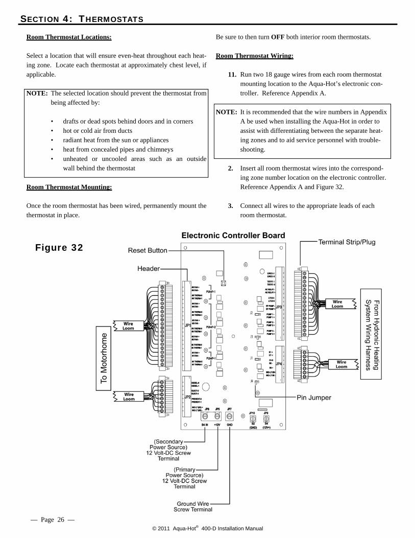
2. Insert all room thermostat wires into the correspond-
ing zone number location on the electronic controller. Reference Appendix A and Figure 32.
3. Connect all wires to the appropriate leads of each
room thermostat.
Figure 32
— Page 26 —
© 2011 Aqua-Hot® 400-D Installation Manual
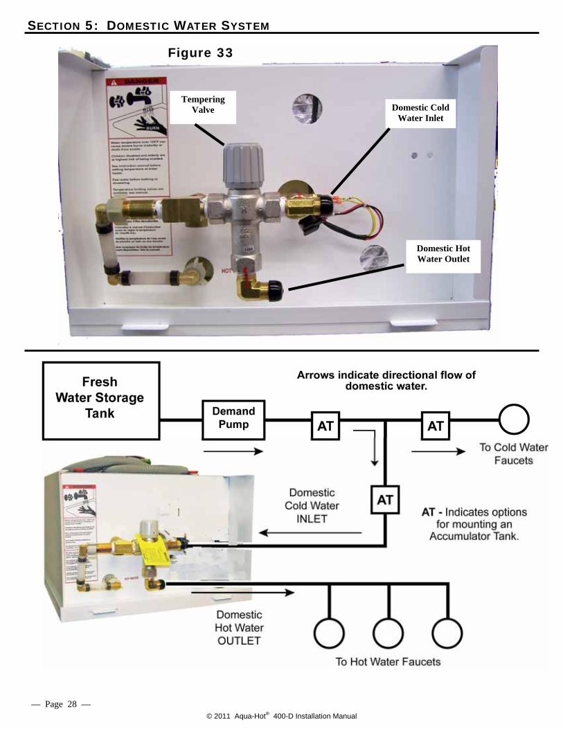
SECTION 5: DOMESTIC WATER SYSTEM
Domestic Water System Requirements:
NOTE: Please note that it may be necessary to utilize an accu-mulator tank within the domestic water system. Refer-ence Figure 34. Although the Aqua-Hot is equipped with a pressure-relief valve, the use of an accumulator tank will help prevent excessive “weeping” of the valve. Manufacturers of pressure-relief valves indi-cate that excessive weeping of these valves will cause the “seat” in the valve to deteriorate, and, in turn, the valve will fail prematurely. For additional informa-tion regarding accumulator tanks, please be sure to reference the Recreational Vehicle Industry Associa-tion’s (RVIA) technical publication titled “Recreational Vehicle Plumbing Systems.” To obtain a copy of this particular publication, please contact RVIA at (703) 620-6003 or visit them online at www.rvia.org.
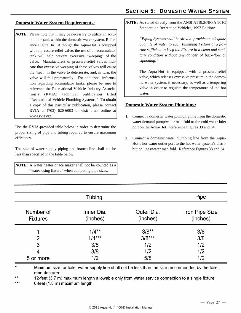
Use the RVIA-provided table below in order to determine the proper sizing of pipe and tubing required to ensure maximum efficiency. The size of water supply piping and branch line shall not be less than specified in the table below.
NOTE: A water heater or ice maker shall not be counted as a
“water-using fixture” when computing pipe sizes.
NOTE: As stated directly from the ANSI A119.2/NFPA 501C Standard on Recreation Vehicles, 1993 Edition:
“Piping Systems shall be sized to provide an adequate
quantity of water to each Plumbing Fixture at a flow rate sufficient to keep the Fixture in a clean and sani-tary condition without any danger of back-flow or siphoning.”
The Aqua-Hot is equipped with a pressure-relief
valve, which releases excessive pressure in the domes-tic water system, if necessary, as well as a tempering valve in order to regulate the temperature of the hot water.
Domestic Water System Plumbing:
1. Connect a domestic water plumbing line from the domestic
water demand pump/water manifold to the cold water inlet port on the Aqua-Hot. Reference Figures 33 and 34.
2. Connect a domestic water plumbing line from the Aqua-
Hot’s hot water outlet port to the hot water system’s distri-bution lines/water manifold. Reference Figures 33 and 34
— Page 27 —
© 2011 Aqua-Hot® 400-D Installation Manual
SECTION 5: DOMESTIC WATER SYSTEM
Figure 33
Figure 34
— Page 28 —
Domestic Hot Water Outlet
Domestic Cold Water Inlet
Tempering Valve
© 2011 Aqua-Hot® 400-D Installation Manual
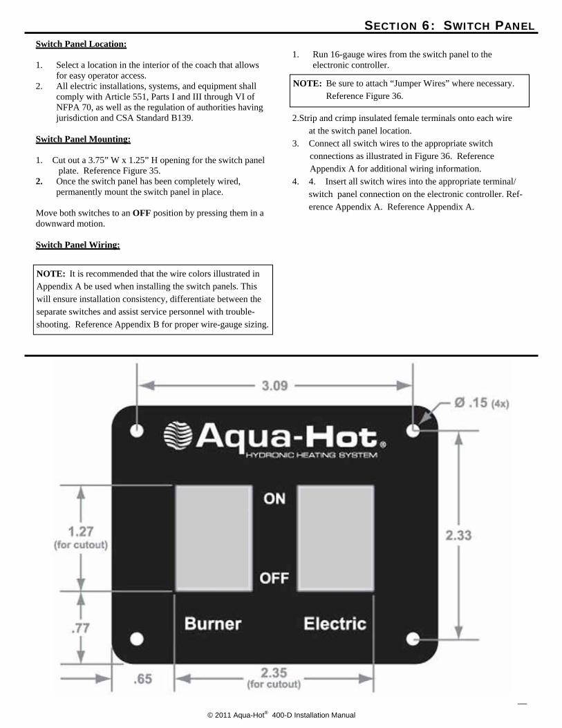
SECTION 6: SWITCH PANEL Switch Panel Location: 1. Select a location in the interior of the coach that allows
for easy operator access. 2. All electric installations, systems, and equipment shall
comply with Article 551, Parts I and III through VI of NFPA 70, as well as the regulation of authorities having jurisdiction and CSA Standard B139.
Switch Panel Mounting: 1. Cut out a 3.75” W x 1.25” H opening for the switch panel
plate. Reference Figure 35. 2. Once the switch panel has been completely wired, permanently mount the switch panel in place. Move both switches to an OFF position by pressing them in a downward motion. Switch Panel Wiring:
1. Run 16-gauge wires from the switch panel to the electronic controller.
2.Strip and crimp insulated female terminals onto each wire at the switch panel location. 3. Connect all switch wires to the appropriate switch
connections as illustrated in Figure 36. Reference Appendix A for additional wiring information.
4. 4. Insert all switch wires into the appropriate terminal/switch panel connection on the electronic controller. Ref-erence Appendix A. Reference Appendix A.
—
NOTE: Be sure to attach “Jumper Wires” where necessary. Reference Figure 36.
NOTE: It is recommended that the wire colors illustrated in Appendix A be used when installing the switch panels. This will ensure installation consistency, differentiate between the separate switches and assist service personnel with trouble-shooting. Reference Appendix B for proper wire-gauge sizing.
© 2011 Aqua-Hot® 400-D Installation Manual
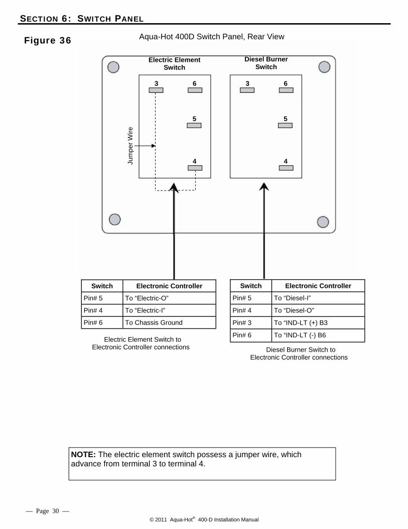
NOTE: The electric element switch possess a jumper wire, which advance from terminal 3 to terminal 4.
SECTION 6: SWITCH PANEL
Figure 36
— Page 30 —
Switch Electronic Controller
Pin# 5 To “Diesel-I”
Pin# 4 To “Diesel-O”
Pin# 3 To “IND-LT (+) B3
Pin# 6 To “IND-LT (-) B6
Diesel Burner Switch to Electronic Controller connections
Electric Element Switch to Electronic Controller connections
Switch Electronic Controller
Pin# 5 To “Electric-O”
Pin# 4 To “Electric-I”
Pin# 6 To Chassis Ground
Electric Element Switch
Diesel Burner Switch
6
4
3
5
6
4
3
5 Ju
mpe
r Wire
Aqua-Hot 400D Switch Panel, Rear View
© 2011 Aqua-Hot® 400-D Installation Manual
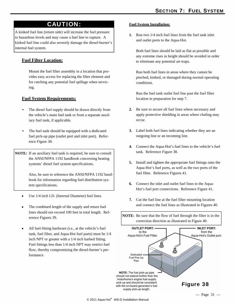
A kinked fuel line (return side) will increase the fuel pressure to hazardous levels and may cause a fuel line to rupture. A kinked fuel line could also severely damage the diesel-burner’s internal fuel system.
Fuel Filter Location: Mount the fuel filter assembly in a location that pro-
vides easy access for replacing the filter element and for catching any potential fuel spillage when servic-ing.
Fuel System Requirements: • The diesel fuel supply should be drawn directly from
the vehicle’s main fuel tank or from a separate auxil-iary fuel tank, if applicable.
• The fuel tank should be equipped with a dedicated
fuel pick-up pipe (outlet port and inlet port). Refer-ence Figure 38.
NOTE: If an auxiliary fuel tank is required, be sure to consult
the ANSI/NFPA 1192 handbook concerning heating systems’ diesel fuel system specifications.
Also, be sure to reference the ANSI/NFPA 1192 hand-
book for information regarding fuel distribution sys-tem specifications.
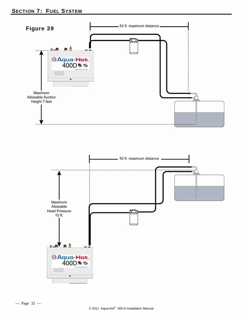
• Use 1/4 inch I.D. (Internal Diameter) fuel lines. • The combined length of the supply and return fuel
lines should not exceed 100 feet in total length. Ref-erence Figures 39.
• All fuel-fitting hardware (i.e., at the vehicle’s fuel
tank, fuel filter, and Aqua-Hot fuel parts) must be 1/4 inch NPT or greater with a 1/4 inch barbed fitting. Fuel fittings less than 1/4 inch NPT may restrict fuel flow, thereby compromising the diesel-burner’s per-formance.
SECTION 7: FUEL SYSTEM
— Page 31 —
CAUTION: Fuel System Installation: 1. Run two 1/4 inch fuel lines from the fuel tank inlet
and outlet ports to the Aqua-Hot. Both fuel lines should be laid as flat as possible and
any extreme rises in height should be avoided in order to eliminate any potential air-traps.
Run both fuel lines in areas where they cannot be
pinched, kinked, or damaged during normal operating conditions. Run the fuel tank outlet fuel line past the fuel filter location in preparation for step 7.
2. Be sure to secure all fuel lines where necessary and
apply protective shielding in areas where chafing may occur.
3. Label both fuel lines indicating whether they are an
outgoing line or an incoming line. 4. Connect the Aqua-Hot’s fuel lines to the vehicle’s fuel
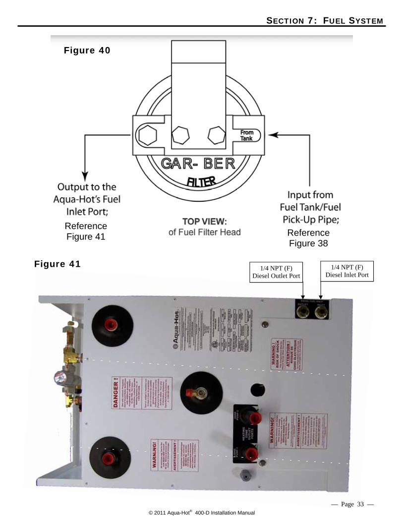
tank. Reference Figure 38. 5. Install and tighten the appropriate fuel fittings onto the
Aqua-Hot’s fuel ports, as well as the two ports of the fuel filter. Reference Figures 41.
6. Connect the inlet and outlet fuel lines to the Aqua-
Hot’s fuel port connections. Reference Figure 41. 7. Cut the fuel line at the fuel filter mounting location
and connect the fuel lines as illustrated in Figures 40.
NOTE: Be sure that the flow of fuel through the filter is in the correction direction as illustrated in Figure 40.
Figure 38
© 2011 Aqua-Hot® 400-D Installation Manual
SECTION 7: FUEL SYSTEM
Figure 39
— Page 32 —
© 2011 Aqua-Hot® 400-D Installation Manual
SECTION 7: FUEL SYSTEM
Reference Figure 38
Figure 40
Reference Figure 41
Figure 41 1/4 NPT (F) Diesel Inlet Port
1/4 NPT (F) Diesel Outlet Port
— Page 33 —

© 2011 Aqua-Hot® 400-D Installation Manual — Page 34 —

© 2011 Aqua-Hot® 400-D Installation Manual — Page 35 —
© 2011 Aqua-Hot® 400-D Installation Manual
SECTION 8: EXHAUST SYSTEM
The Aqua-Hot’s exhaust is hot and must be kept away from any heat-sensitive material. DO NOT direct exhaust downward as a fire may re-sult when parked in dry, grassy areas. Exhaust must not terminate beneath the vehicle or beneath an open able window or vent. DO NOT terminate the exhaust pipe within the awn-ing area of the motor home, if applicable. Be sure to keep the exhaust away from the slide-out areas. All Aqua-Hot exhaust system installations MUST utilize the two black pipe nipples and the black pipe elbow, which are provided with the heating system, in the configuration best suited for the particular recreational vehicle application. Fail-ure to conform could create a hazardous situation and will void the Aqua-Hot’s ETL product listing. NOTE: Refer to “Internal Combustion Engine Exhausts and
Vehicle Wall Openings” in RVIA’s ANSI/NFPA 1192 Handbook for the Recreational Vehicle Stan-dards, as well as the National Fire Protection Associa-tion’s (NFPA) 1192 Standard on Recreational Vehi-cles for additional information.
Exhaust System Requirements:
The exhaust must be able to freely exit away
from the vehicle without any obstructions. Angle the exhaust pipe towards the rear of the
vehicle so that the exhaust fumes will naturally move away while the vehicle is in motion. Ref-erence Figure 45.
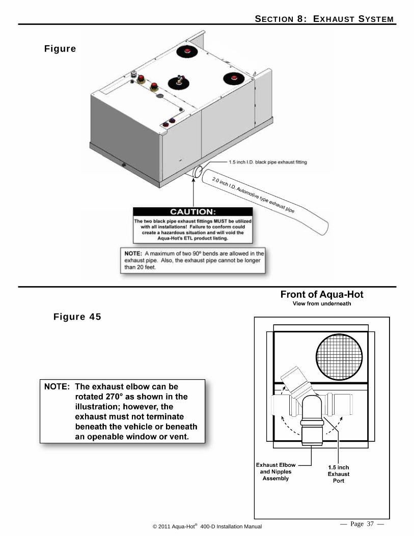
Use standard 2 inch automotive-type exhaust pip-
ing and avoid bends, if possible. A minimum 1.75” ID automotive-type exhaust pipe may be used. Reference Figures 44 and 47.
A maximum of three 90º exhaust pipe bends are
allowed. Reference Figure 44.
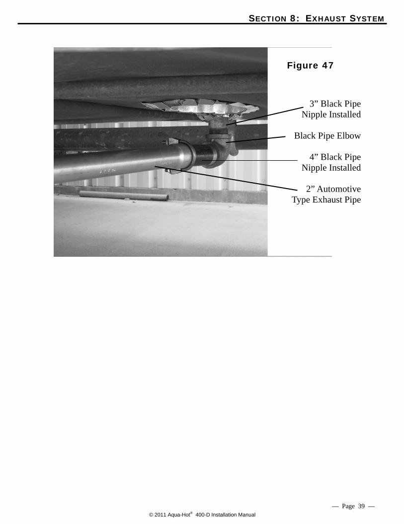
Do not use galvanized pipe or fittings; only black-iron pipe and fittings should be used. Reference Figure 47.
The total length of exhaust pipe should not ex-
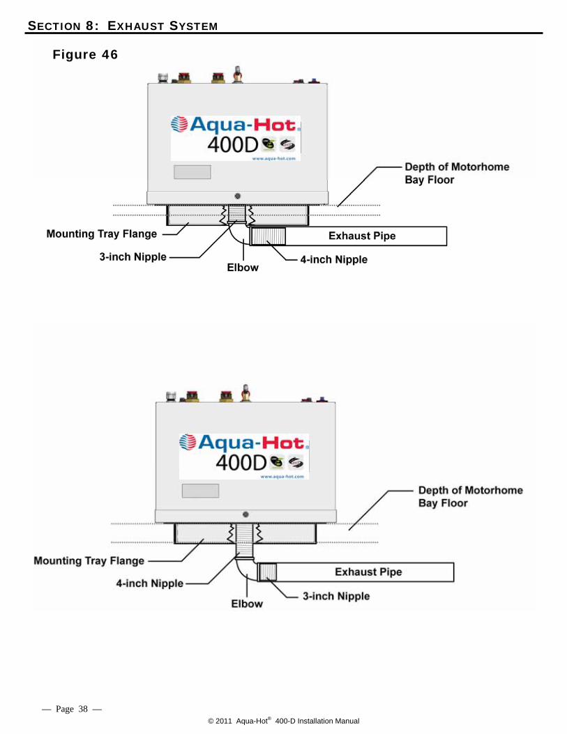
ceed 27.5 feet. The Aqua-Hot is supplied with a 3 inch and a 4
inch black pipe nipple (1½ inch diameter) along with a 1½ inch exhaust elbow. Reference Figure 45. These three exhaust system components MUST BE utilized with all product installations. Be sure to reference Figure 46 and 47 to deter-mine which exhaust nipple should be connected directly to the Aqua-Hot’s exhaust port (i.e., the 3 inch or the 4 inch black pipe nipple).
NOTE: Should the particular application require more
than 27.5 feet of exhaust pipe, please contact the Aqua-Hot Heating Systems Product Application Department at 1-800-685-4298 for assistance.
Installing the Exhaust System:
1. Run the exhaust pipe to the driver’s side or the
back of the vehicle and ensure that the exhaust fumes cannot enter into the passenger compart-ment. Be sure to keep the exhaust away from the slide-out areas.
2. Be sure to secure the end of the exhaust pipe to
the vehicle with the proper exhaust hanger/support hardware.
— Page 36 —
© 2011 Aqua-Hot® 400-D Installation Manual
SECTION 8: EXHAUST SYSTEM
Figure
Figure 45
— Page 37 —
NOTE: A maximum of 27.5 feet with three 90⁰ bends are allowed in the exhaust pipe. A minimum of 1.75” ID automo-tive type exhaust pipe may be used.
1.75
© 2011 Aqua-Hot® 400-D Installation Manual
SECTION 8: EXHAUST SYSTEM
Figure 46
— Page 38 —
© 2011 Aqua-Hot® 400-D Installation Manual — Page 39 —
3” Black Pipe Nipple Installed
Black Pipe Elbow
4” Black Pipe
Nipple Installed
2” Automotive Type Exhaust Pipe
Figure 47
SECTION 8: EXHAUST SYSTEM
© 2011 Aqua-Hot® 400-D Installation Manual
SECTION 9: ELECTRONIC CONTROLLER WIRING Electronic Controller Wiring: NOTE: Please reference Appendix A for specific wiring infor-
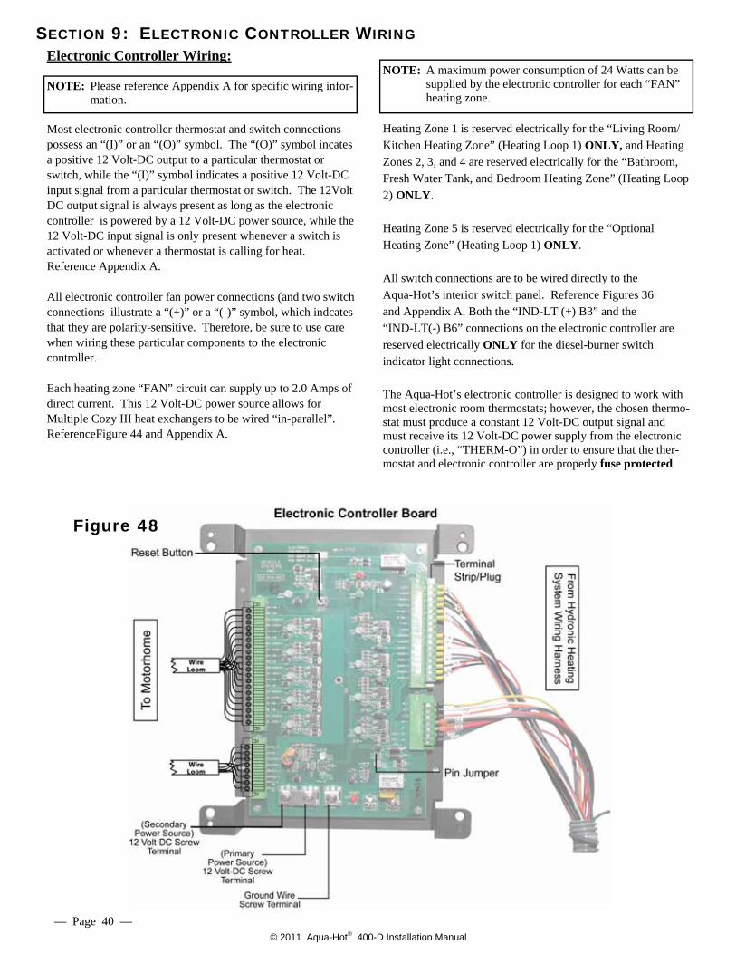
mation. Most electronic controller thermostat and switch connections possess an “(I)” or an “(O)” symbol. The “(O)” symbol incates a positive 12 Volt-DC output to a particular thermostat or switch, while the “(I)” symbol indicates a positive 12 Volt-DC input signal from a particular thermostat or switch. The 12Volt DC output signal is always present as long as the electronic controller is powered by a 12 Volt-DC power source, while the 12 Volt-DC input signal is only present whenever a switch is activated or whenever a thermostat is calling for heat. Reference Appendix A. All electronic controller fan power connections (and two switch connections illustrate a “(+)” or a “(-)” symbol, which indcates that they are polarity-sensitive. Therefore, be sure to use care when wiring these particular components to the electronic controller. Each heating zone “FAN” circuit can supply up to 2.0 Amps of direct current. This 12 Volt-DC power source allows for Multiple Cozy III heat exchangers to be wired “in-parallel”. ReferenceFigure 44 and Appendix A.
NOTE: A maximum power consumption of 24 Watts can be supplied by the electronic controller for each “FAN” heating zone.
Heating Zone 1 is reserved electrically for the “Living Room/ Kitchen Heating Zone” (Heating Loop 1) ONLY, and Heating Zones 2, 3, and 4 are reserved electrically for the “Bathroom, Fresh Water Tank, and Bedroom Heating Zone” (Heating Loop 2) ONLY. Heating Zone 5 is reserved electrically for the “Optional Heating Zone” (Heating Loop 1) ONLY. All switch connections are to be wired directly to the Aqua-Hot’s interior switch panel. Reference Figures 36 and Appendix A. Both the “IND-LT (+) B3” and the “IND-LT(-) B6” connections on the electronic controller are reserved electrically ONLY for the diesel-burner switch indicator light connections.
The Aqua-Hot’s electronic controller is designed to work with most electronic room thermostats; however, the chosen thermo-stat must produce a constant 12 Volt-DC output signal and must receive its 12 Volt-DC power supply from the electronic controller (i.e., “THERM-O”) in order to ensure that the ther-mostat and electronic controller are properly fuse protected
Figure 48
— Page 40 —
© 2011 Aqua-Hot® 400-D Installation Manual
DO NOT activate the diesel-burner until the antifreeze and water heating solution has been added to the boiler tank and the heating system has been completely bled of air. Operating the Aqua-Hot without the antifreeze and water heating solution will cause serious damage to the Aqua-Hot’s boiler tank. DO NOT connect the 12 Volt-DC power to the Aqua-Hot if the vehicle requires welding. Electrical welding will cause serious damage to the diesel-burner controller and the Aqua-Hot’s electronic controller. NOTE: Reference Appendix B for proper wire-gauge sizing. Please note that under full-load conditions, the Aqua- Hot can draw as much as 20 Amps of DC current. Because the Aqua-Hot is designed to shut down in the event that the DC voltage level drops too low to properly operate, it is imperative that the proper wire e
be determined and utilized.
SECTION 9: ELECTRONIC CONTROLLER WIRING
CAUTION:
WARNING
Figure 49
Be sure to protect against accidental shorting (i.e., chassis shorting) by incorporating a 20-Amp rated in- line fuse into the power wire at the battery location. Reference Figure 50. All electric installations, systems, and equipment shall comply with Article 551, Parts I and III through VI of NFPA 70, as well as the regulation of authorities
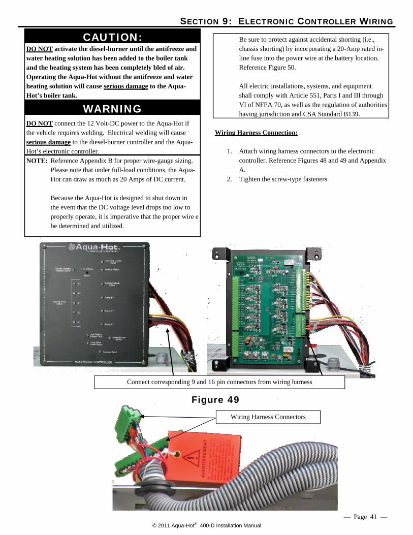
having jurisdiction and CSA Standard B139. Wiring Harness Connection:
1. Attach wiring harness connectors to the electronic
controller. Reference Figures 48 and 49 and Appendix A.
2. Tighten the screw-type fasteners
Wiring Harness Connectors
Connect corresponding 9 and 16 pin connectors from wiring harness
— Page 41 —
© 2011 Aqua-Hot® 400-D Installation Manual
Main Battery Disconnect
SECTION 9: ELECTRONIC CONTROLLER WIRING
— Page 42 —
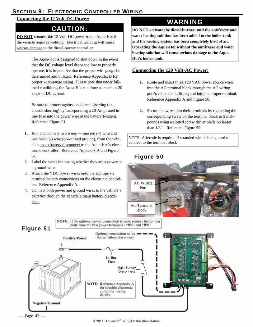
Connecting the 12 Volt-DC Power:
DO NOT connect the 12 Volt-DC power to the Aqua-Hot if the vehicle requires welding. Electrical welding will cause serious damage to the diesel-burner controller. The Aqua-Hot is designed to shut down in the event
that the DC voltage level drops too low to properly operate, it is imperative that the proper wire gauge be determined and utilized. Reference Appendix B for proper wire-gauge sizing. Please note that under full-load conditions, the Aqua-Hot can draw as much as 20 amps of DC current.
Be sure to protect against accidental shorting (i.e.,
chassis shorting) by incorporating a 20-Amp rated in-line fuse into the power wire at the battery location. Reference Figure 51.
1. Run and connect two wires –– one red (+) wire and
one black (-) wire (power and ground), from the vehi-cle’s main battery disconnect to the Aqua-Hot’s elec-tronic controller. Reference Appendix A and Figure 51.
2. Label the wires indicating whether they are a power or a ground wire.
3. Attach the VDC power wires onto the appropriate terminal/battery connections on the electronic control-ler. Reference Appendix A.
4. Connect both power and ground wires to the vehicle’s batteries through the vehicle’s main battery discon-nect.
DO NOT activate the diesel-burner until the antifreeze and water heating solution has been added to the boiler tank and the heating system has been completely bled of air. Operating the Aqua-Hot without the antifreeze and water heating solution will cause serious damage to the Aqua-Hot’s boiler tank.
Connecting the 120 Volt-AC Power: 1. Route and insert three 120 VAC power source wires
into the AC terminal block through the AC wiring port’s cable clamp fitting and into the proper terminal. Reference Appendix A and Figure 50.
2. Secure the wires into their terminals by tightening the
corresponding screw on the terminal block to 5 inch-pounds using a slotted screw driver blade no larger than 1/8” . Reference Figure 50.
AC Wiring Port
AC Terminal Block
WARNING
Figure 50
CAUTION:
NOTE: A ferrule is required if stranded wire is being used to connect to the terminal block
Figure 51
© 2011 Aqua-Hot® 400-D Installation Manual
SECTION 10: PURGING THE SYSTEMS
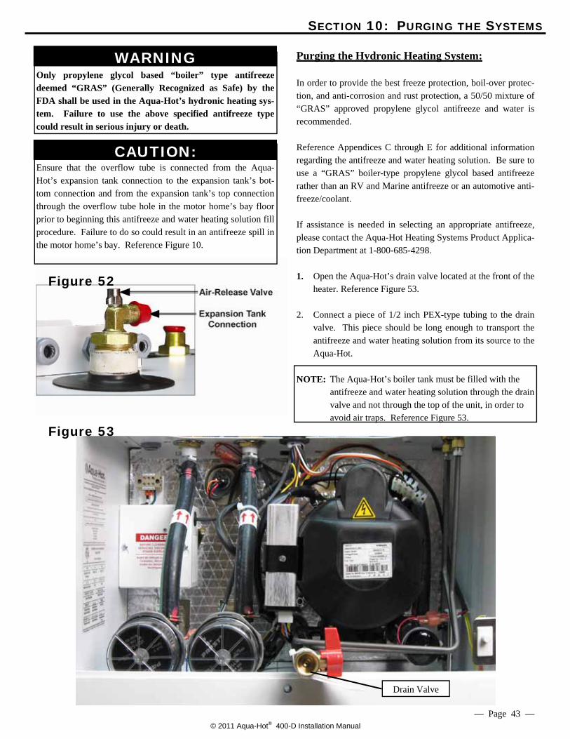
Only propylene glycol based “boiler” type antifreeze deemed “GRAS” (Generally Recognized as Safe) by the FDA shall be used in the Aqua-Hot’s hydronic heating sys-tem. Failure to use the above specified antifreeze type could result in serious injury or death.
Ensure that the overflow tube is connected from the Aqua-Hot’s expansion tank connection to the expansion tank’s bot-tom connection and from the expansion tank’s top connection through the overflow tube hole in the motor home’s bay floor prior to beginning this antifreeze and water heating solution fill procedure. Failure to do so could result in an antifreeze spill in the motor home’s bay. Reference Figure 10.
Purging the Hydronic Heating System:
In order to provide the best freeze protection, boil-over protec-tion, and anti-corrosion and rust protection, a 50/50 mixture of “GRAS” approved propylene glycol antifreeze and water is recommended. Reference Appendices C through E for additional information regarding the antifreeze and water heating solution. Be sure to use a “GRAS” boiler-type propylene glycol based antifreeze rather than an RV and Marine antifreeze or an automotive anti-freeze/coolant. If assistance is needed in selecting an appropriate antifreeze, please contact the Aqua-Hot Heating Systems Product Applica-tion Department at 1-800-685-4298.
1. Open the Aqua-Hot’s drain valve located at the front of the
heater. Reference Figure 53. 2. Connect a piece of 1/2 inch PEX-type tubing to the drain
valve. This piece should be long enough to transport the antifreeze and water heating solution from its source to the Aqua-Hot.
NOTE: The Aqua-Hot’s boiler tank must be filled with the
antifreeze and water heating solution through the drain valve and not through the top of the unit, in order to avoid air traps. Reference Figure 53.
Figure 52
Figure 53
— Page 43 —
Drain Valve
CAUTION:
WARNING
© 2011 Aqua-Hot® 400-D Installation Manual
SECTION 10: PURGING THE SYSTEMS
3. Fill the Aqua-Hot completely with the 50/50 mixture of antifreeze and water heating solution. This will take approximately five gallons; look for the solution to enter the overflow tube attached to the expansion tank connection on top of the Aqua-Hot.
4. When refilling, open the air-release valve located on the
expansion tank connection to release air pockets. Reference Figure 52. Hold the valve open until all air
is released. Be sure the valve is closed when finished by hand-tightening. Look for the solution to enter the overflow tube attached to the expansion tank connection on top of the Aqua-Hot.
5. Close the drain valve.
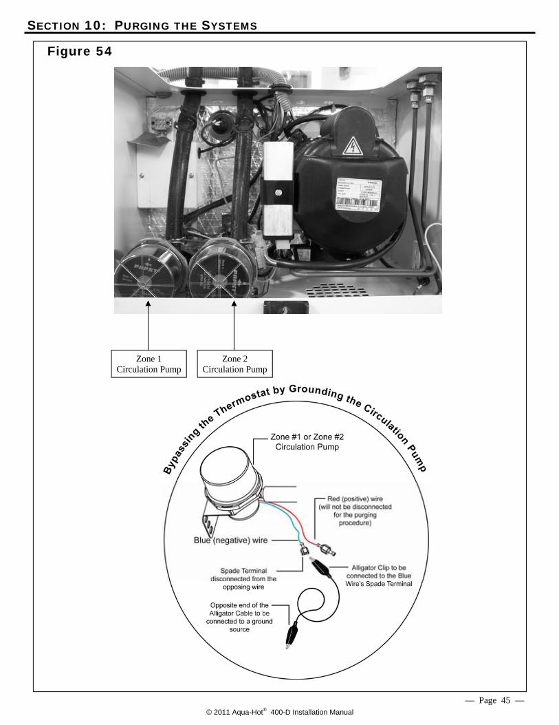
Purging the System by Grounding the Zone Thermostat Connection:
1. Ensure that the boiler tank has been filled with the appro-
priate 50/50 mixture of antifreeze and water heating solution.
2. Locate the heating zone circulation pumps. Reference
Figure 54.
3. Take the circulation pump’s blue (negative) wire and dis-connect it from the connector of the opposing wire. Reference Appendix A.
4. Connect an alligator clip to the spade terminal on the cir-
culation pump’s blue (negative) wire and clip the op-posite end of the cable to a ground source.
NOTE: The circulation pump will activate as soon as the
pump is connected to a ground source; therefore, dis-connect the alligator clip from the ground source dur-ing the antifreeze and water heating solution filling procedure.
5. Allow the circulation pump to operate for approximately 1
-3 minutes in order to purge the corresponding heating loop, then remove the alligator clip from the ground source.
6. Open the drain valve and completely fill the Aqua-Hot’s
boiler tank with additional antifreeze and water heat-ing solution.
7. Repeat steps 5 and 6 for both heating loops until all air has been completely bled from the entire heating system.
NOTE: All air is bled from the heating system when both
plumbing lines are free of air. Reference Figure 26.
8. Once the systems have been purged, disconnect the alliga-tor clips from the ground source and the circulation pump’s wires. Reconnect the pump’s wires as origi-nally configured. Reference Figure 54.
9. Check the Aqua-Hot’s expansion tank and top it off to the
cold level mark with the 50/50 antifreeze and water mixture, if necessary.
10. Ensure that each circulation pump’s wiring has been re-
turned to its original configuration. Reference Figure 54.
Purging the Domestic Water System:
Verify that the domestic water tank contains fresh water prior to bleeding the fresh water system. 1. Ensure that the vehicle’s domestic water pump has 12
Volt-DC power, then activate it by opening each hot water faucet, one at a time, and running the water until all air is purged from the domestic water system.
2. Once the domestic water system is completely bled, check
for leaks in the domestic water system.
— Page 44 —
© 2011 Aqua-Hot® 400-D Installation Manual
SECTION 10: PURGING THE SYSTEMS
— Page 45 —
Zone 1 Circulation Pump
Zone 2 Circulation Pump
Figure 54
— Page 46 —
SECTION 11: INITIAL START-UP
Activating the Aqua-Hot: 1. Reinstall the Aqua-Hot’s main access cover and the
fastener, which secures the front of the Aqua-Hot’s access cover to the mounting tray.
NOTE: The main access cover must be installed prior to op-
eration; a safety switch exists, which will prevent the Aqua-Hot from operating whenever the main access cover is not properly installed.
2. Move the diesel burner switch to the ON position for
approximately ten seconds ONLY, then switch it OFF.
NOTE: This procedure will purge the diesel-burner’s fuel
system by allowing the heater’s fuel pump to com-plete its normal 30-150 second shutdown/purge cycle.
3. After the purge cycle has ended, repeat once more. 4. Move the diesel-burner switch to the ON position and
leave it on in order to activate the diesel-burner.
NOTE: It will take approximately 10 seconds before the diesel-burner will ignite and exhaust can be heard exiting the heater.
Allow approximately 10-20 minutes for the Aqua-Hot
to reach normal operating temperature (approximately 190°F).
5. Move the Aqua-Hot’s electric element switch to the
ON position in order to supply 120 Volt-AC power to the electric heating element.
NOTE: Both the 12 Volt-DC powered diesel-burner and the
electric heating element are thermostatically con-trolled. Either or both heating sources will automati-cally maintain the temperature of the boiler tank’s antifreeze and water heating solution.
The Aqua-Hot is now ready for normal operation and use.
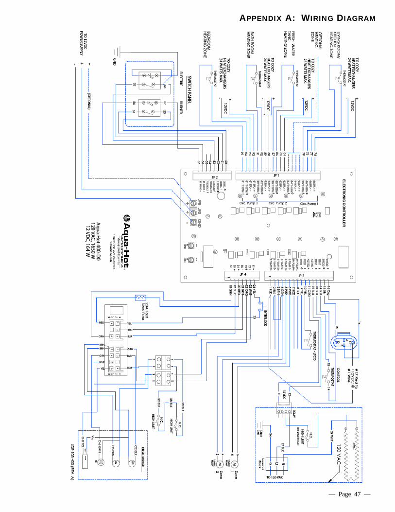
APPENDIX A: WIRING DIAGRAM
— Page 47 —
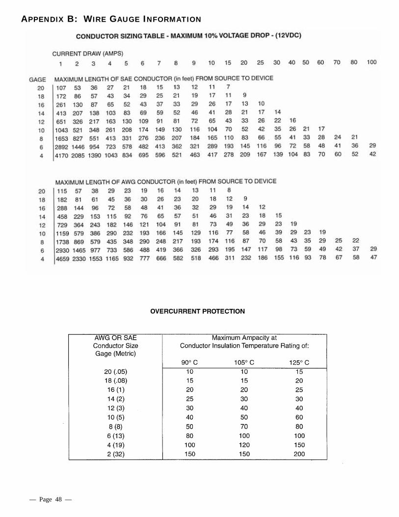
APPENDIX B: WIRE GAUGE INFORMATION
— Page 48 —
© 2011 Aqua-Hot® 400-D Installation Manual
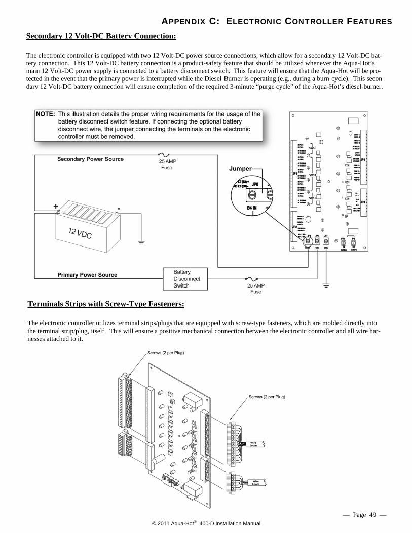
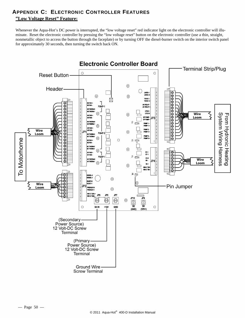
APPENDIX C: ELECTRONIC CONTROLLER FEATURES Secondary 12 Volt-DC Battery Connection: The electronic controller is equipped with two 12 Volt-DC power source connections, which allow for a secondary 12 Volt-DC bat-tery connection. This 12 Volt-DC battery connection is a product-safety feature that should be utilized whenever the Aqua-Hot’s main 12 Volt-DC power supply is connected to a battery disconnect switch. This feature will ensure that the Aqua-Hot will be pro-tected in the event that the primary power is interrupted while the Diesel-Burner is operating (e.g., during a burn-cycle). This secon-dary 12 Volt-DC battery connection will ensure completion of the required 3-minute “purge cycle” of the Aqua-Hot’s diesel-burner.
Terminals Strips with Screw-Type Fasteners: The electronic controller utilizes terminal strips/plugs that are equipped with screw-type fasteners, which are molded directly into the terminal strip/plug, itself. This will ensure a positive mechanical connection between the electronic controller and all wire har-nesses attached to it.
— Page 49 —
© 2011 Aqua-Hot® 400-D Installation Manual
APPENDIX C: ELECTRONIC CONTROLLER FEATURES “Low Voltage Reset” Feature: Whenever the Aqua-Hot’s DC power is interrupted, the “low voltage reset” red indicator light on the electronic controller will illu-minate. Reset the electronic controller by pressing the “low voltage reset” button on the electronic controller (use a thin, straight, nonmetallic object to access the button through the faceplate) or by turning OFF the diesel-burner switch on the interior switch panel for approximately 30 seconds, then turning the switch back ON.
— Page 50 —
© 2011 Aqua-Hot® 400-D Installation Manual — Page 51 —
APPENDIX D: ANTIFREEZE TYPES
The following information addresses the necessary usage of a propylene glycol based “boiler” type antifreeze in the Aqua-Hot. Propylene glycol is a safer alternative to the more toxic ethylene glycol antifreeze; however, as mandated by IAPMO (International Association of Plumbing and Me-chanical Officials), only those propylene glycol based “boiler” type antifreezes deemed “Generally Recognized as Safe” (GRAS) by the FDA should be utilized. Because of the significant impact various types of antifreeze can have on a hydronic heating system, including the level of safety provided, it has been recognized that there is a need to provide an explanation regarding two additional prominent types of antifreeze/coolant available. The following infor-mation should be utilized as an educational means of ensur-ing that the proper type of propylene glycol based antifreeze is selected: RV & Marine Antifreeze: These types of propylene glycol based antifreeze products are formulated specifically for “winterizing” applications only. Although RV & Marine antifreeze is often “Generally Recognized as Safe” by the FDA, it should never be used in
the Aqua-Hot’s Hydronic Heating System. This type of anti-freeze is not formulated to transfer heat, which is essential to the heating system’s functionality and does not contain rust inhibitors. Please note, however, that RV & Marine anti-freeze can be utilized to winterize the Aqua-Hot’s Domestic Hot Water Heating System. Automotive Antifreeze/Coolant:
These types of propylene glycol based antifreeze products are formulated specifically to protect automotive engines against corrosion, freezing temperatures, and overheating. They also have excellent heat transfer and thermal conduc-tivity characteristics. Although these types of antifreeze products are considered less toxic and safer than ethylene glycol for people, pets, and the environment, they are not “Generally Recognized as Safe” (GRAS) rated by the FDA. Therefore, they must be marked with a “harmful if swal-lowed” warning. This additional warning is required be-cause these types of antifreeze products contain high levels of chemical rust inhibitors. Due to their potentially hazard-ous properties, they should never be used in the Aqua-Hot’s Hydronic Heating System.
In order to ensure maximum performance and longevity of an Aqua-Hot heating system’s boiler tank and associated components, it has been determined that there is a need to use distilled, de-ionized, or soft water in combination with concentrated propylene glycol for the Aqua-Hot’s antifreeze and water heating solution. Please note that this is only nec-essary when mixing concentrated propylene glycol antifreeze with water; suppliers of pre-mixed antifreeze are responsible for the use of high-quality (distilled, de-ionized, or soft) wa-ter when preparing their antifreeze for sale.
APPENDIX E: ANTIFREEZE MIXTURE WATER QUALITY RECOMMENDATIONS
Hard water possesses a high-level of calcium and magnesium ions, which deplete the propylene glycol antifreeze’s corro-sion inhibitors. This, in turn, causes the antifreeze and water heating solution to begin turning acidic, which can corrode the Aqua-Hot’s Boiler tank and associated components pre-maturely. Therefore, concentrated propylene glycol should be diluted with distilled, de-ionized, or soft water which is 80 ppm or less in total hardness. The local water agency should have up-to-date water quality reports which should indicate if the local tap water is within this guideline.
APPENDIX F: ANTIFREEZE TERMS AND MIXTURE RATIO
— Page 52 —
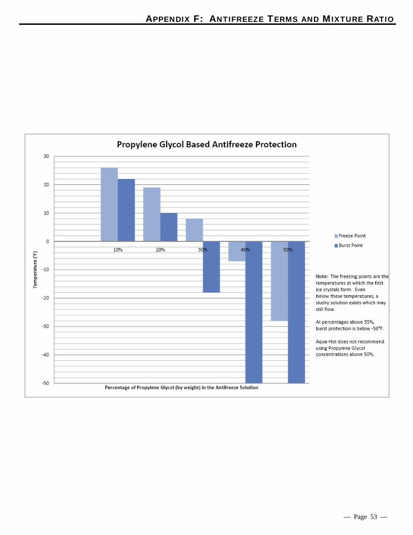
Propylene Glycol Based Antifreeze Solution: The following information addresses the process of selecting a propylene glycol based antifreeze solution that provides adequate freeze, boiling, and rust/anti-corrosive protection. A propylene glycol antifreeze solution that is 35% to 50% propylene glycol is recommended. Antifreeze solution with 50% propylene glycol will result in a freeze point of approxi-mately -28ºF and a boil point of approximately 222ºF.
Aqua-Hot sells CAMCO propylene glycol based antifreeze solution in the following packages:
The following information should be utilized for the purpose of clarifying some terms commonly associated with anti-freeze. Freeze Point and Burst Point: Antifreeze solution lowers the freezing point of any liquid, to which it has been added, by preventing the formation of ice crystals; however, as the ambient temperature continues to decline, the water in the solution will attempt to attain a solid state. The point in which the water begins to solidify is termed the “Freeze Point.” Although the water in the solu-tion has begun to freeze, producing a “slushy” consistency, the antifreeze in the solution will continue to combat the normal expansion of the solution as it freezes. The point in which the solution can begin to expand, due to colder tem-peratures, is called the “Burst Point.” Once the solution reaches the burst point, the potential is present for ruptured pipes to exist. The burst point of the antifreeze and water heating solution is dependent upon the brand of propylene glycol antifreeze employed.
Boiling Point: The Aqua-Hot utilizes the propylene glycol based (PPG) antifreeze and water heating solution as a transportation means for the heat produced from the internal processes. The PPG antifreeze solution absorbs the heat created until its boiling point is reached; it is at this point that the liquid turns to a gas and is expelled to prevent the heating system from overheating. Each time the boiling point is reached, a loss of efficiency occurs because the heat produced is expelled rather than utilized for the function of the heating system. Therefore, a higher boiling point is desired in order to com-bat the loss of efficiency, which allows the antifreeze to transport the heat created from the internal process through-out the motorhome where it can be utilized productively rather than dissipating due to its change from a liquid to a gas. Rust and Anti-Corrosive Inhibitors: Another major function of antifreeze solution is to provide protection to the internal metal components of the Aqua-Hot hydronic heating system from corrosion and rust. Antifreeze is able to perform this function by the addition of rust and anti-corrosive inhibitors, which are designed specifically to activate in a water solution. Summary: Antifreeze solution has three basic functions: freeze protec-tion, boil-over protection, and anti-corrosion and rust protec-tion. PPG Antifreeze solution is also primarily responsible for heat transfer; however, propylene glycol itself does not pos-sess acceptable heat transfer characteristics. Therefore, as water is an excellent heat conductor, it is added to the mix-ture. PPG antifreeze solution , mixed with water, that is 35% to 50% propylene glycol is recommended to provide the best performance combination of the aforementioned functions. If excess propylene glycol exists within an antifreeze and water heating solution, the water’s heat absorption properties are compromised, which could ultimately inhibit the Aqua-Hot from providing adequate domestic hot water and interior heating. Additionally, if the antifreeze and water heating solution contains over 70 percent propylene glycol, the freezing point is actually raised, resulting in less freeze protection. Please reference the attached graphical representation regarding the percentage of antifreeze to water and how it directly affects the solution’s freezing point.
NOTE: As the installer of this Aqua-Hot system, you must refer to the information and chart in Appendix E to determine the percentage of propylene glycol your antifreeze solution should contain for the level of protection you require.
Part Number Container Size % Propylene Glycol
MSX-300-270 Gallon Bottle 68%
MSX-300-275 Quart Bottle 98%
MSX-300-280 55 Gallon Drum 68%
NOTE: Propylene glycol based antifreeze solution is not 100% propylene glycol. It is a mixture of propylene glycol, rust and anti-corrosive inhibitors, and water.
APPENDIX F: ANTIFREEZE TERMS AND MIXTURE RATIO
— Page 53 —
© 2011 Aqua-Hot® 400-D Installation Manual
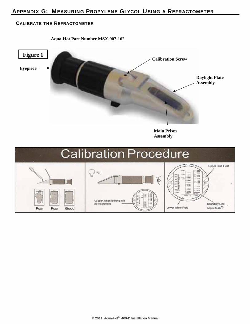
Figure 1
Eyepiece
Calibration Screw
Daylight Plate Assembly
Main Prism Assembly
CALIBRATE THE REFRACTOMETER
Aqua-Hot Part Number MSX-907-162
APPENDIX G: MEASURING PROPYLENE GLYCOL USING A REFRACTOMETER
© 2011 Aqua-Hot® 400-D Installation Manual
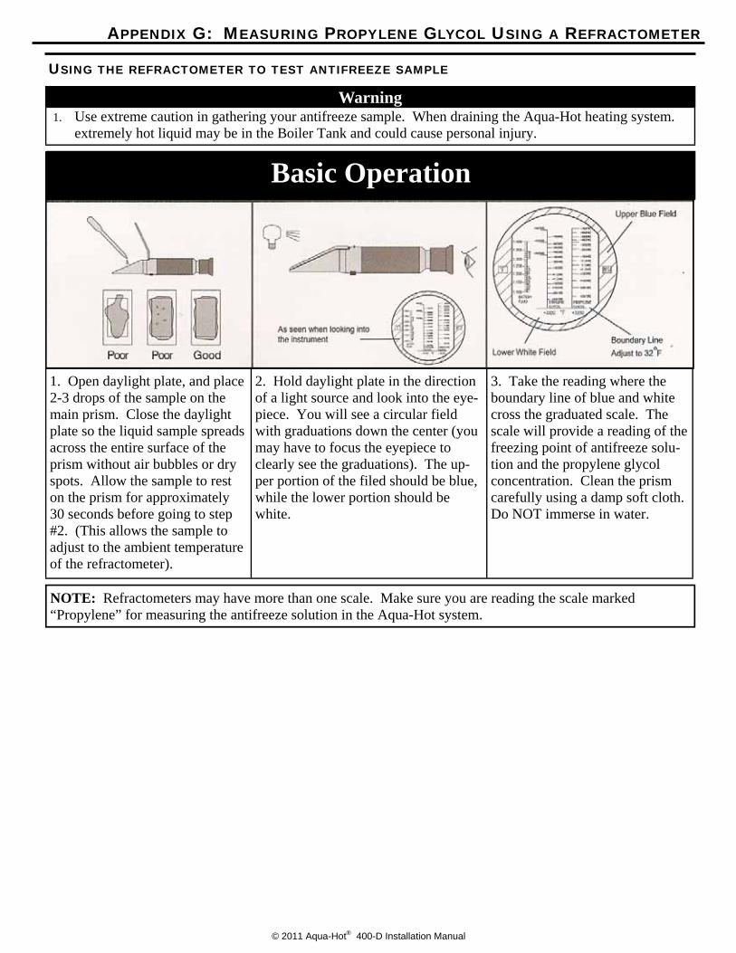
Warning 1. Use extreme caution in gathering your antifreeze sample. When draining the Aqua-Hot heating system.
extremely hot liquid may be in the Boiler Tank and could cause personal injury.
NOTE: Refractometers may have more than one scale. Make sure you are reading the scale marked “Propylene” for measuring the antifreeze solution in the Aqua-Hot system.
Basic Operation
1. Open daylight plate, and place 2-3 drops of the sample on the main prism. Close the daylight plate so the liquid sample spreads across the entire surface of the prism without air bubbles or dry spots. Allow the sample to rest on the prism for approximately 30 seconds before going to step #2. (This allows the sample to adjust to the ambient temperature of the refractometer).
2. Hold daylight plate in the direction of a light source and look into the eye-piece. You will see a circular field with graduations down the center (you may have to focus the eyepiece to clearly see the graduations). The up-per portion of the filed should be blue, while the lower portion should be white.
3. Take the reading where the boundary line of blue and white cross the graduated scale. The scale will provide a reading of the freezing point of antifreeze solu-tion and the propylene glycol concentration. Clean the prism carefully using a damp soft cloth. Do NOT immerse in water.
USING THE REFRACTOMETER TO TEST ANTIFREEZE SAMPLE
APPENDIX G: MEASURING PROPYLENE GLYCOL USING A REFRACTOMETER

LTE-907-609
15549 East Highway 52 | Fort Lupton, CO 80621 Toll free: 800.685.4298 | phone: 303.659.8221 | fax:303.857.9000
www.aquahot.com