INSTALLATION MANUAL - Amazon Simple Storage Service · INSTALLATION MANUAL. SLIDING LADDER RACK....
9
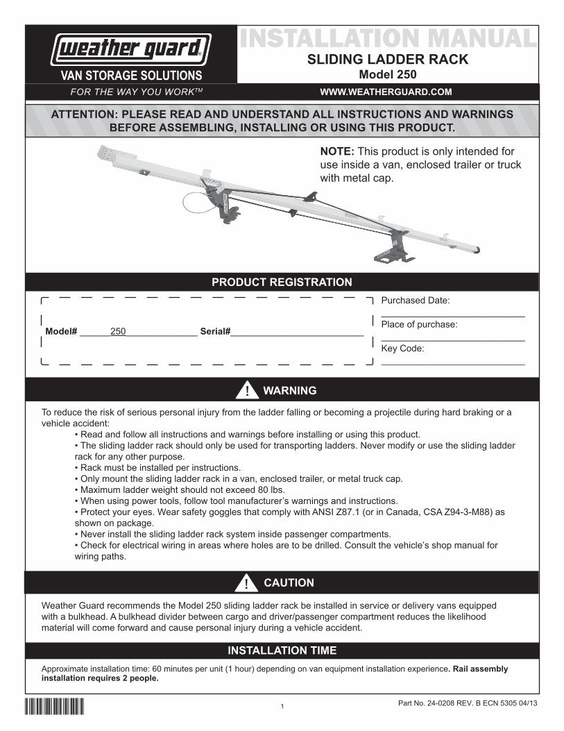
1 INSTALLATION MANUAL SLIDING LADDER RACK Model 250 ATTENTION: PLEASE READ AND UNDERSTAND ALL INSTRUCTIONS AND WARNINGS BEFORE ASSEMBLING, INSTALLING OR USING THIS PRODUCT. WARNING WWW.WEATHERGUARD.COM VAN STORAGE SOLUTIONS CAUTION FOR THE WAY YOU WORK TM PRODUCT REGISTRATION Model# ______250______________ Serial#__________________________ Purchased Date: ____________________________ Place of purchase: ____________________________ Key Code: ____________________________ 24-0208 Part No. 24-0208 REV. B ECN 5305 04/13 NOTE: This product is only intended for use inside a van, enclosed trailer or truck with metal cap. Weather Guard recommends the Model 250 sliding ladder rack be installed in service or delivery vans equipped with a bulkhead. A bulkhead divider between cargo and driver/passenger compartment reduces the likelihood material will come forward and cause personal injury during a vehicle accident. To reduce the risk of serious personal injury from the ladder falling or becoming a projectile during hard braking or a vehicle accident: • Read and follow all instructions and warnings before installing or using this product. • The sliding ladder rack should only be used for transporting ladders. Never modify or use the sliding ladder rack for any other purpose. • Rack must be installed per instructions. • Only mount the sliding ladder rack in a van, enclosed trailer, or metal truck cap. • Maximum ladder weight should not exceed 80 lbs. • When using power tools, follow tool manufacturer’s warnings and instructions. • Protect your eyes. Wear safety goggles that comply with ANSI Z87.1 (or in Canada, CSA Z94-3-M88) as shown on package. • Never install the sliding ladder rack system inside passenger compartments. • Check for electrical wiring in areas where holes are to be drilled. Consult the vehicle’s shop manual for wiring paths. INSTALLATION TIME Approximate installation time: 60 minutes per unit (1 hour) depending on van equipment installation experience. Rail assembly installation requires 2 people.
-
Upload
nguyenhanh -
Category
Documents
-
view
222 -
download
0
Transcript of INSTALLATION MANUAL - Amazon Simple Storage Service · INSTALLATION MANUAL. SLIDING LADDER RACK....
1
INSTALLATION MANUALSLIDING LADDER RACK
Model 250
ATTENTION: PLEASE READ AND UNDERSTAND ALL INSTRUCTIONS AND WARNINGS BEFORE ASSEMBLING, INSTALLING OR USING THIS PRODUCT.
WARNING
WWW.WEATHERGUARD.COMVAN STORAGE SOLUTIONS
CAUTION
FOR THE WAY YOU WORKTM
PRODUCT REGISTRATION
Model# ______250______________ Serial#__________________________
Purchased Date:____________________________Place of purchase:____________________________Key Code:____________________________
24-0208Part No. 24-0208 REV. B ECN 5305 04/13
NOTE: This product is only intended for use inside a van, enclosed trailer or truck with metal cap.
Weather Guard recommends the Model 250 sliding ladder rack be installed in service or delivery vans equipped with a bulkhead. A bulkhead divider between cargo and driver/passenger compartment reduces the likelihood material will come forward and cause personal injury during a vehicle accident.
To reduce the risk of serious personal injury from the ladder falling or becoming a projectile during hard braking or a vehicle accident:
• Readandfollowallinstructionsandwarningsbeforeinstallingorusingthisproduct.• Theslidingladderrackshouldonlybeusedfortransportingladders.Nevermodifyorusetheslidingladderrack for any other purpose.• Rackmustbeinstalledperinstructions.• Onlymounttheslidingladderrackinavan,enclosedtrailer,ormetaltruckcap.• Maximumladderweightshouldnotexceed80lbs.• Whenusingpowertools,followtoolmanufacturer’swarningsandinstructions.• Protectyoureyes.WearsafetygogglesthatcomplywithANSIZ87.1(orinCanada,CSAZ94-3-M88)asshown on package.• Neverinstalltheslidingladderracksysteminsidepassengercompartments.• Checkforelectricalwiringinareaswhereholesaretobedrilled.Consultthevehicle’sshopmanualforwiring paths.
INSTALLATION TIMEApproximateinstallationtime:60minutesperunit(1hour)dependingonvanequipmentinstallationexperience. Rail assembly installation requires 2 people.

2
INSTALLATION INSTRUCTIONS
PARTS LIST
TOOLS REQUIRED• Electric Drill • Ruler • Ratchet Wrench• 5/16” Hex Driver Bit • 7/16” Wrench • Lithium Grease• Phillips Screw Driver • 7/16” Deep Well Socket
Step 1: RAIL ASSEMBLY INSTALLATIONUsing connecting brackets (2), connect rail sections (3) using eight 1/4-20 x 3/4” carriage bolts, 1/4” washers and 1/4-20 nylon lock nuts. NOTE: The installation instructions below are written for the installation of this product to the roof
ribs of a van or truck cap. This rack can be mounted to the side wall of a trailer if desired, using the same steps described below.
NOTE: Depending on the size and type of your vehicle, the rail assembly may need to be cut to length for proper installation, Measure the distance inside the van, and cut the assembled rail to the correct length.
Determine the rail mounting location inside vehicle (center, off-center, side). Measure the three van rib locations from the rear of the van, starting from the upper inside of the rear door jamb, and measuring forward. Record those dimensions.
Fasten the rear mounting bracket to the rear of the rail assembly (end opposite cut end) using two 1/4-20 x 3/4” carriage bolts, 1/4” washers and 1/4-20 nylon lock nuts. See Figure 1a. From the rear of the rear mounting bracket, mark the rail assembly at the recorded rib locations. Fasten a mounting bracket just tight enough to be adjusted by hand, centered at each mark, using one 1/4-20 x 3/4” carriage bolt, 1/4” washer and 1/4-20 nylon lock nut each.
(1) Cord guide
(4) Strut channel nut
(2) Stop plate
(1) 1.25 OD Washer
(4) Hex head cap screw,1/4 x 20 x 1
(20)Nylon lock nut, 1/4 x 20
(2) Carriage bolt,1/4 x 20 x 1-1/2
(24)1/4” Flat Washer
(1) Pan head machine screw,1/4 x 20 x 7/8
(2) Shock cord
(4) Lock washer
(1) Adjustable mount
(1) Fixed mount
(1) Adjustable arm
(1) Front cradle
(1) Inside side catch
(1) Outside side catch
(1) Fixed catch
(17)Carriage bolt,1/4 x 20 x 3/4
(1) Safety cable assy.
(3) Rail
(2) Connecting bracket
(3) Mounting bracket
(1) Vinyl cap
(8)1/4 - 14 x 3/4self-drilling screw
(1) Rear mounting bracket
CAUTION
Rail assembly must be attached to all three roof ribs for proper installation.

3
Step 2: INSTALLING FIXED MOUNTMeasure from the foot of the ladder to the bottom rung. From the back of the rail assembly measure the samedistanceandmarktherail.Thiswillbetheapproximatelocationofthefixedmount.Installthefixedmount with grooves facing the front of the vehicle. Allow for position adjustment using fasteners shown in Figure 2.
Figure 1
Figure 1a
RearMounting
Bracket
Place the rail assembly in the vehicle in position. Determine whether the rear mounting bracket needs to bemodified.Itmaybeoffsettotherailassemblyorhaveaportionofitremovedortheangleoftheflangechangedtomeetthedoorjambflush,ifnecessary.Adjustthemountingbracketlocationsontherailassem-bly if necessary, to insure that the mounting brackets can be properly fastened to the roof ribs.
Remove the rail assembly from the roof ribs, and tighten the mounting brackets securely.
Placetherailassemblybackinposition,andfastenittotheroofribsandreardoorjambwithtwo1/4-14x3/4”selfdrillingscrewsand1/4”flatwashersperbracket.
Fastenthecordguideapproximately30”infromtherearoftherailassembly,usinga1/4-20x7/8”panheadmachinescrew,1-1/4”ODwasher,1/4”flatwasherand1/4-20nylonlocknut.Adjustthe30”dimen-sion for obstructions if necessary.
StrutChannel
Nut
Fixed Mount
1/4” Flat Washer
Lock Washer
1/4-20 x 1Hex HeadCap Screw
Adjustable Arm
Front Cradle
AdjustableMount
Safety CableFixedCatch
Figure 2
Figure 3
Figure 4

4
CAUTIONDo not over tighten fasteners.
Step 3: INSTALLING SLIDING MOUNTInserttheslidingmountintotherailassemblywiththegroovedportionfacingtherearofthevehicle.Installthe vinyl cap over the cut end of the rail assembly.Step 4: FRONT CRADLE ASSEMBLY INSTALLATION NOTE: Ifinstallingthisslidingladderracktothesidewallofatrailer,proceedtoStep10fortheside
catch assembly. Usingtwo1/4-20x7/8”carriagebolts,1/4”flatwashers,and1/4-20nylonlocknuts,affixfrontcradletoextensionarm.Attachtoslidingmount.Withone1/4-20x1-1/2”carriagebolt,1/4”flatwasher,and1/4-20nylonlocknut,adjustthedepthofthecradletofittheheightofyourladder.Tightencarriageboltcompletely(Figure3).
Step 5: FIXED CATCHUsingone1/4-20x1-1/2”carriagebolt,1/4”flatwasher,and1/4-20nylonlocknut,affixthefixedcatchandsafetycabletothefixedmountallowingforadjustingthedepthtofitthebottomrungoftheladder.Tightencarriage bolt completely (Figure 4).
StrutChannel
Nut
Fixed Mount
1/4” Flat Washer
Lock Washer
1/4-20 x 1Hex HeadCap Screw
Adjustable Arm
Front Cradle
AdjustableMount
Safety CableFixedCatch
Figure 2
Figure 3
Figure 4
StrutChannel
Nut
Fixed Mount
1/4” Flat Washer
Lock Washer
1/4-20 x 1Hex HeadCap Screw
Adjustable Arm
Front Cradle
AdjustableMount
Safety CableFixedCatch
Figure 2
Figure 3
Figure 4
WARNING
• Safetycablemustbeattachedperinstructionsforladdertobeproperlysecuredtorackandvehicle.• Donotovertightenfasteners.

5
Step 6: ADJUSTING MOUNTING POSITIONSPlace ladder onto the front cradle and slide forward to the stowed position. Place the bottom rung of the ladderontothefixedcatch.Thiswillbethefinalpositionofthefixedcatchassembly.Gentlyremovetheladdersoasnottomovethefixedcatchandfinishsecuringthefixedcatchassemblyinplace.
Step 7: SHOCK CORD INSTALLATIONSlidetheshockcordsthroughtheadjustablemountshockcordholes.Makesurethehogringisatthebackoftheunit.Nextslidethecordsthroughtheshockcordguideholes,andthenthroughthefixedmountshock cord holes.
Place ladder onto rack and slide forward while holding the shock cord. When the ladder is in the stowed po-sition,firmlypulltheshockcordandslideitintotheholdingslotonthebackofthefixedmount(seefigure5).
Make sure to have enough tension on the shock cord to securely hold the ladder in place. Tie a double knot intotheendoftheshockcordatthispoint,andinsertthecordsintheslotsinthefixedmount.Tucktheexcessintothebackofthefixedmount(seefigure5).
Step 8: INSTALL FORWARD AND REAR STOPSRecommendedpositionoftheforwardstopisapproximately1”infrontoftheslidingmountinthestowedposition. The position of the stop should allow just enough travel to slide the ladder forward to place the bottom rung onto the adjustable catch as well as ladder removal.
Rear stop should be placed far enough forward to limit travel of the sliding mount allowing you to pull the laddereasilyoffofthefrontcradleassemblywithouthittingthefixedcatch.
CAUTION
• Elasticcordscansnapbackandstrikeyoureye.Donotoverstretch.Keepyourbodyandfaceclear.• Elasticcordsmustbeproperlyadjusted.Failuretoadjustcordtensionforlengthofladdermayallowladderto fall.
Figure 5
Figure 6
CAUTION
• FixedCatchassemblyisnotcompletelysecuredatthispoint.Whenplacingladderintopositionitcouldfall.• Donotallowanyonedirectlyunderneathortothesideofladderduringthisinstallationstep,excepttohelpwith mounting.
WARNING
FrontStopPlatemustbeinstalledtopreventtheslidingcatchfromdislodgingduringhardbrakingorinavehicle accident.

6
Before loading ladder into rack:1. WEATHERGUARDrecommendstheModel250slidingladderrackbeinstalledinserviceordeliveryvans equipped with a bulk head. A bulkhead divider between cargo and driver/passenger compartment reduces the likelihood material will come forward and cause personal injury during a vehicle accident.2. The sliding ladder rack is designed to be loaded from the back of a cargo van or pickup truck with ametal cap.3. Beforeloadingaladder,makesuretheelasticcordsandthestopbracketareinstalledandpositionedcorrectly.SeeInstallationsteps7&8onpages3&4.Ifadifferentsizeladderistobeloadedthenthestopbracket and the elastic cords must be adjusted or the ladder will fall from the rack.4. Inspectthepartsoftheladderrackbeforeusing.Ifanypartisbroken,bentordamagedinanywaydonotuserack.SeeMaintenancesectionforreplacementparts.
Loading ladder into rack:1. Ensure the ladder is clean and dry.2. Openvan’sreardoorsortruckhatchtoaccessrack.3. Pullonelasticcordstomovetheslidingcatchtowardtherear.4. Position the ladder with the step side down (non-step side up).5. Liftthetopoftheladderandplaceitinthefrontcradle.SeeFigure7.
USAGE INSTRUCTIONS
WARNING
• Inspecttheslidingladderrackbeforeeachuse.Donotuserackifitisdamagedordeterioratedinanyway.• Donotplaceshorterladderinrackadjustedforlongerladder.Alwaysadjuststopplateandelasticcordsforlength of ladder being loaded.• Incorrectloadingorunloadingoftheslidingladderrackcouldallowladdertofallandcauseseriouspersonalinjury or property damage.• Neveroperatetherackwithpersonsseatedbeloworneartherackandladder.• Becarefulwhenloadingladderintotheslidingladderrackifstandingonslickoricyground.• Donotloadorunloadladderwhenvehicleismoving.
Optional InstallationStep 10: SIDE MOUNTING INSTALLATION INSTRUCTIONS (ONLY)Installsidecatchbracketstoadjustablemountwithtwo1/4-20x7/8”carriagebolts,1/4”flatwashers,and1/4-20nylonlocknutsasshowninFigure6.Installrailassemblytosideofenclosedtrailer.
Figure 5
Figure 6
Step 9: RAIL LUBRICATIONApply a generous amount of lithium grease to the inside of the rail allowing for smooth travel of the sliding front cradle.
7
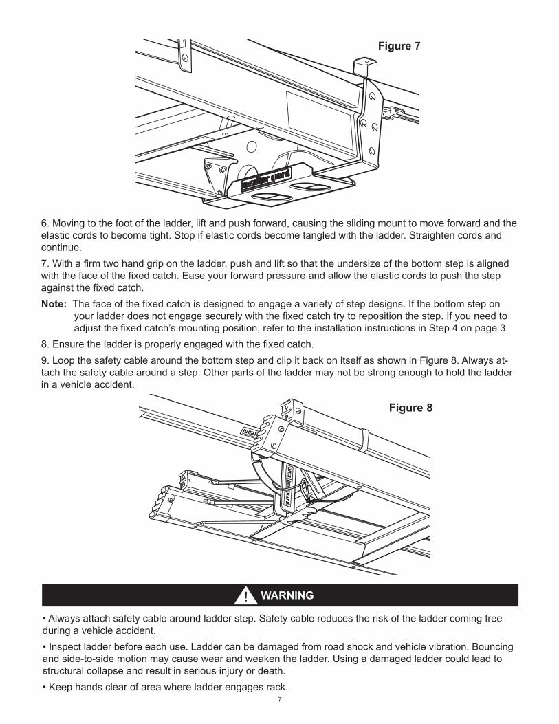
6. Movingtothefootoftheladder,liftandpushforward,causingtheslidingmounttomoveforwardandtheelasticcordstobecometight.Stopifelasticcordsbecometangledwiththeladder.Straightencordsandcontinue.7. Withafirmtwohandgripontheladder,pushandliftsothattheundersizeofthebottomstepisalignedwiththefaceofthefixedcatch.Easeyourforwardpressureandallowtheelasticcordstopushthestepagainstthefixedcatch.Note: Thefaceofthefixedcatchisdesignedtoengageavarietyofstepdesigns.Ifthebottomstepon
yourladderdoesnotengagesecurelywiththefixedcatchtrytorepositionthestep.Ifyouneedtoadjustthefixedcatch’smountingposition,refertotheinstallationinstructionsinStep4onpage3.
8. Ensuretheladderisproperlyengagedwiththefixedcatch.9. LoopthesafetycablearoundthebottomstepandclipitbackonitselfasshowninFigure8.Alwaysat-tachthesafetycablearoundastep.Otherpartsoftheladdermaynotbestrongenoughtoholdtheladderin a vehicle accident.
Figure 7
Figure 8
Figure 7
Figure 8
WARNING
• Alwaysattachsafetycablearoundladderstep.Safetycablereducestheriskoftheladdercomingfreeduring a vehicle accident.• Inspectladderbeforeeachuse.Laddercanbedamagedfromroadshockandvehiclevibration.Bouncingand side-to-side motion may cause wear and weaken the ladder. Using a damaged ladder could lead to structural collapse and result in serious injury or death.• Keephandsclearofareawhereladderengagesrack.

8
WARNING
• Toreducetheriskofpersonalinjury:• DoNotuseladderrackwithmissingordamagedparts.• Inspectelasticcordsforwear.Ifclothcoveringisfrayed,cordcouldbreakunexpectedly.Donotuserack.• Maintaingreaseonrail.
Conduct periodic inspection of your sliding ladder rack for wear and tear, damage or loose parts. Repair or replace as necessary.Apply a generous amount of lithium grease to the inside of the rail allowing for smooth travel of the sliding front cradle.Checktheelasticcordsfordamageandwear.Ifclothcoveringisfrayed,cordcouldbreakunexpectedly.Replace the cords before using the rack.Checkthesafetycablefordamageorbreakage.Lookforbrokenstrands.Iffoundreplacecablebeforeusing the rack.
GENERAL MAINTENANCE
SERVICE PARTS
1
2
Unloading ladder from rack:1. To un-load ladder from rack, reverse the loading process above while following these steps.2. Make sure you have secure footing and a clear path behind your vehicle to walk the ladder out.3. Checkthattheladderhasnotshiftedintherackandisstillsecurelyheldbythefixedcatch.4. Remove the safety cable from around the step.5. Pushtheladderforwardandthendowntodisengagethestepfromthefaceofthefixedcatch.Bepreparedfor the push-back from the elastic cords.6. Walkawayfromthevehicleuntilthetopoftheladderhasslidtonearthefixedcatch.7. Forlongorheavyladders,setthebottomoftheladderdowntothegroundandthenmoveupthesideofthe ladder to a position and lift the top from the front cradle.
ITEM NO. PART NO. DESCRIPTION1 7947 SafetyCable
2 7948 ShockCord(1pair)
3 7949 BoltKit(notshown)
FOR REPLACEMENT PARTS GO TO WWW.WEATHERGUARD.COM
9
KNAACKLLCLIMITEDLIFETIMEWARRANTYFORWEATHERGUARD®PRODUCTS
WEATHER GUARD® Products — Limited Lifetime Warranty (Purchasedonorafter1/1/2009)
KnaackLLC(the“Manufacturer”)warrantstotheoriginalpurchaseronlythatWEATHERGUARD® Truck and Van Products (the“WEATHERGUARD®Product”)willbefreefromdefectsinmaterialandworkmanshipfromthedateofpurchaseandcontinuingfortheexpectedlifetimeoftheWEATHERGUARD® Product. A copy of the original sales receipt must be supplied to the Manufacturer at the time a warranty claim is made. This warranty terminates if the original purchaser transfers the WEATHERGUARD® Product to any other person.
What is Covered AllWEATHERGUARD®ProductsidentifiedabovethatarepurchasedonorafterJanuary1,2009.
What We Will Do to Correct Problems Subjecttothelimitationsandexclusionsdescribedinthislimitedwarranty,theManufacturerwillremedydefectsinmaterialsor workmanship by providing one of the following remedies at its option and without charge to the original purchaser for parts orlabor:(a)repairingthedefectiveportionoftheWEATHERGUARD®Productor(b)replacingtheentireWEATHERGUARD® Product.Inaddition,themanufacturermayelectatitsoption,nottorepairorreplacetheWEATHERGUARD® Product, but ratherissuetotheoriginalpurchaserarefundequaltothepurchasepricepaidfortheWEATHERGUARD® Product or a credit tobeusedtowardthepurchaseofnewWEATHERGUARD® Product.
What is Not Covered Thislimitedwarrantyexpresslyexcludes:
• Defectscausedbynormalwearandtear,cosmeticrust,scratches,accidents,unlawfulvehicleoperation,ormodificationtotheproduct,oranytypesorrepairofaWEATHERGUARD® Product other than those authorized orprovided by the Manufacturer.
• DefectsresultingfromconditionsbeyondtheManufacturer’scontrolincluding,butnotlimitedtomisuse,overloading,orfailuretoassemble,mountorusetheWEATHERGUARD®ProductinaccordancewiththeManufacturer’swritteninstructionsorguidelinesincludedwiththeWEATHERGUARD® Product or made available to the original purchaser.
• Damagetothecontentsoftheboxorvehicle.
• TOTHEEXTENTPERMITTEDBYLAW,INNOEVENTSHALLTHEMANUFACTURERBELIABLEFORANYINCIDENTAL,SPECIAL,INDIRECT,ORCONSEQUENTIALDAMAGES,INCLUDINGANYECONOMICLOSS,WHETHERRESULTINGFROMNONPERFORMANCE,USE,MISUSEORINABILITYTOUSETHEWEATHERGUARD®PRODUCTORTHEMANUFACTURER’SNEGLIGENCE.
No Other Express Warranty Applies ThisLimitedLifetimeWarrantyisthesoleandexclusivewarrantyforWEATHERGUARD® products. No employee, agent, dealer,orotherpersonisauthorizedtoalterthiswarrantyormakeanyotherwarrantyonbehalfofKnaackLLC.
Notification Procedures IftheWEATHERGUARD® Product does not conform with the terms of this limited warranty, the original owner must promptly notifytheManufacturerinwritingupondiscoveryofthenonconformity.Inordertoreceivetheremediesunderthislimitedwarranty, the warranty claim must describe the nature of the nonconformity, and a copy of the original sales receipt, invoice, billorotherproofofpurchasemustaccompanytheclaim.RepairsormodificationsmadetotheWEATHERGUARD® Product by other than the Manufacturer or its authorized agent will nullify this limited warranty. Coverage under this limited warranty is conditionedatalltimesupontheowner’scompliancewiththeserequirednotificationandrepairprocedures.Warrantyclaimsmust include reciprocal contact information and may be made via certified mail to:
24-0208Part No. 24-0208 REV. B ECN 5305 04/13
Knaack LLCATTN: Warranty Claims
420 E. Terra Cotta Avenue Crystal Lake, IL 60014
If you have any questions, please call toll free at 1-800-456-7865.©2013 Knaack LLC