
Installation & Maintenance Manual for the India Mark II ... · Installation & Maintenance Manual...
45
Edition 2008 Installation & Maintenance Manual for the India Mark II Handpump skat Resource Centre and Consultancy for Development RWSN Rural Water Supply Network
Transcript of Installation & Maintenance Manual for the India Mark II ... · Installation & Maintenance Manual...

Edition 2008
Installation & Maintenance Manualfor the India Mark II Handpump
skat Resource Centre and
Consultancy for Development
RWSN Rural WaterSupply Network

1
Installation and Maintenance Manual for the India Mark II Handpump
Edition 2008 The Installation and Maintenance Manual for the India Mark II Handpump is intended to assist all users of this handpump, especially to give a guideline for the installation procedures as also for maintaining the pump including the pump platform. This document results from several years of work carried out by UNICEF Eritrea in partnership with SKAT – RWSN. Special thanks are given to the staff of the Debub region of Eritrea, especially Mr. Giorghis Tecle; and Mr. Eric Toft and Yodit Hiruy of UNICEF Eritrea. Suggestions for improvement on the manual are welcomed for future updates and can be sent to SKAT – RWSN at the address given below. Drawings: SKAT – RWSN, Photographs: Meera & Ceiko Pumps Ptv. Ltd., Hyderabad, India, UNICEF Delhi, India and SKAT –
RWSN, St.Gallen, Switzerland. Copyright: SKAT - RWSN
Provided the source SKAT – RWSN is acknowledged, extracts of this publication may be reproduced.
Distribution: SKAT
Vadianstrasse 42 CH-9000 St.Gallen Switzerland
Phone: +41 71 228 54 54 Fax: +41 71 228 54 55 E-mail: [email protected] or [email protected] URL: http://www.skat.ch or http://www.rwsn.ch

2
Installation and Maintenance Manual for the India Mark II Handpump
Contents
Page
Background Information ……………………………………………………. 3
Pump Features and Supporting Documents ………..……………….. 3
Part 1 Installation of the India Mark II Handpump ……………….. 7 Preparation for Handpump Installation ……………………….. 12 Tools and Materials required for Installation ……………………….. 13 Preparation of “Below Ground Components” ……………………….. 13 Preparation of “Above Ground Components” ……………………….. 16
Handpump Installation Sequences ………………………………….. 18 Installation of “Below Ground Components” ……………………….. 18 Installation of “Above Ground Components” ……………………….. 21
Performance Testing …………………………………………………. 27
Part 2 Maintenance and Repair …………………….……………... 28 Preventive Maintenance ……………………………………………….… 28 Time Intervals of Preventive Maintenance Interventions ….……..…. 28 Maintenance & Repair of the India Mark II Pump ……………................ 29 Dismantling Procedure Sequences ……….………….……………… 30 Dismantling of “Above Ground Components” ……………………….. 30 Dismantling of “Below Ground Components” ……………………….. 34
Maintenance of Pump Surrounding ……………………………….…. 36
Part 3 Recording of Interventions ……………………………….. 37
Annexes Annex 1 Trouble Shooting …………………………………………… 38 Annex 2 List of Fast Moving Spare Parts ……………………….…. 39 Annex 3 Installation Card / Maintenance Card / Monitoring Card 40 Annex 4 Spare Parts for India Mark II Handpump ………………… 43

3
Background Information The “India Mark II Handpump” was developed in India more than 30 years ago and it is designed for lifting water from deep wells up to 50 m. Strict maintenance of deep-well pumps is very important to keep them operational. Therefore the pump users must be trained and willing to make regular maintenance in a disciplined manner. Spare parts that require regular replacements must be easily available and stored in a sufficient number nearby the pump users. Good quality is another important factor, which can increase the lifetime of a pump considerably. Therefore all pump components needs to be checked strictly prior to installation. This manual is specially designed for installation personnel and includes therefore additional information in connection with the India Mark II Handpump. For the pump users, a Maintenance Card should be developed, which contains pictures to shows all maintenance interventions in a simple way. To keep this Maintenance Card in good shape for many years, it can be plastic-laminated before given to the pump users. Pump Features On Pages 4 and 5: drawings of India Mark II Handpumps installed on boreholes and dug-wells are shown with all technical names of pump details used in this manual. On Page 5: a section drawing of a pump cylinder is showing the arrangement of the different components. Supporting Documents
a) India Mark Handpump Specification, Revision 2-2007
b) Moulding Guidelines for the Production of Rubber Components, Revision 1-1999

4
Drawing of an India Mark II Pump installed in a Borehole

5
Drawing of an India Mark II Pump installed on a Dug-well

6
Drawing of the India Mark II Pump Cylinder

7
Part 1 Installation of the India Mark II Pump General Comments
Sustained safe drinking water supply and sanitation facilities are essential to improve the living conditions of the rural population. The provision of safe water helps to combat water borne diseases and improves community health in general. Benefits of a safe water supply can reach far beyond considerations of public health and have a positive influence on the general well being, economic status and quality of life in a community.
Protection of Water Source
If a well site is chosen and the well drilled (or dug) into the ground at a site which is elevated and away from water logged areas during the rainy season, the water which percolates from an underground aquifer into the well should be pure enough to drink. However, a water point obviously attracts a great deal of human contact. This is a potential source of contamination and should be protected against. The safety measures are as follows:
Well Siting
a) The well should be in an elevated place, so that during the rainy season the water will run away from it, rather than into it,
b) It should be at least 40 meters away from a latrine and uphill of the latrine, c) It should be at least 30 meters away from a cattle kraal, and uphill of the kraal, c) It should be well away from any depressed area in the ground, such as hollows used for
rubbish dumping, hollows used for brick making or any other areas where water might collect. Hygiene Education and Water Supply
Throughout the water supply process, it is vital to bear in mind the important linkages between health, hygiene education and water. An awareness of the intimate relationships between these factors should be made clear to all water users. Before the arrival of a new or improved water supply system, the water users of a village should receive hygiene training with regard to the collection, storage and use of water. For example, the transmission of diseases through contaminated water may not be understood in the community.

8
Cleanliness in the area of the water point is an important factor in the overall impact of the introduction of a new or improved facility. If the surrounding area is not kept clean and free of animals, debris, waste and stagnant water, the water point could become a hub for the transmission of many infectious diseases. In this respect, the ability of the community to manage the system and ensure regular cleaning of the water point is vital.
Suggested Platform Design
If the area around a well is allowed to become dirty, and waste and stagnant water is allowed to accumulate, it will become a source of infection for the users. Standing in bare feet in stagnant water or mud is a serious health risk in the tropics since the open water provides an ideal breeding ground for many types of parasite and/or disease carrier. Awareness of the direct links between hygiene and water must start at the collection point, otherwise the possible benefits from an improved water supply will be lost. The construction of a platform (or slab) at the wellhead is an important contribution to the general hygiene in a community. In addition to discouraging the accumulation of stagnant water at the surface, the slab will help to prevent the contamination of the well through the infiltration of dirty water back into the aquifer.
The following points are important: a) The slab surrounding the water point should
be made as wide as possible from properly made reinforced concrete of good quality. The water outlet (spout) should be placed in the centre of the slab, so that spill water gets collected and can run away thorough the drainage channel.
b) All surfaces should slope towards the drainage channel and the edges of the slab should be raised.
c) The slab should be well reinforced with steel wire, to prevent cracking. Dirty water can pass through cracks in a poorly constructed slab and contaminate the well beneath.
The shape of the slab is not as important as its capacity to drain water away from the well as quickly as possible and to ensure wastewater dispersal in a hygienic manner. Where possible, the drain can lead to an area of vegetation, such as banana plants or a vegetable garden. If this is not an option, a soak-pit can be built or a trough for watering livestock can be provided. It is important that construction of the slab does not commence until the soil around the well, which was disturbed by the construction activities, has had an opportunity to settle properly.
Selection of Platform Type
Consultation with the community is a must before a decision is taken on the platform layout. In the following page you will find the typical platform design used for handpumps installed on boreholes. This is an indicative layout that can be modified to suit communities’ needs, which may include the following:
• Facilities for washing clothes, • Facility for bathing, • Trough for cattle watering, • Collection of water for small-scale irrigation etc.

9

10
11
Fencing the Water Source
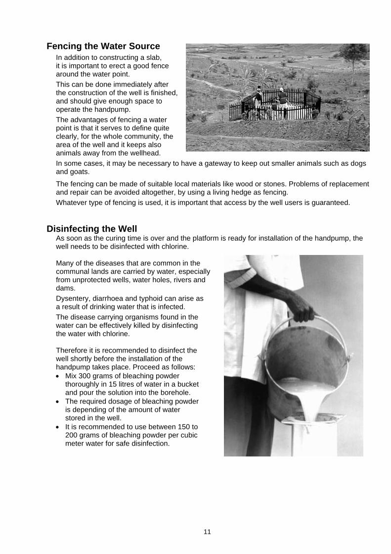
In addition to constructing a slab, it is important to erect a good fence around the water point. This can be done immediately after the construction of the well is finished, and should give enough space to operate the handpump. The advantages of fencing a water point is that it serves to define quite clearly, for the whole community, the area of the well and it keeps also animals away from the wellhead. In some cases, it may be necessary to have a gateway to keep out smaller animals such as dogs and goats.
The fencing can be made of suitable local materials like wood or stones. Problems of replacement and repair can be avoided altogether, by using a living hedge as fencing. Whatever type of fencing is used, it is important that access by the well users is guaranteed.
Disinfecting the Well
As soon as the curing time is over and the platform is ready for installation of the handpump, the well needs to be disinfected with chlorine.
Many of the diseases that are common in the communal lands are carried by water, especially from unprotected wells, water holes, rivers and dams. Dysentery, diarrhoea and typhoid can arise as a result of drinking water that is infected. The disease carrying organisms found in the water can be effectively killed by disinfecting the water with chlorine.
Therefore it is recommended to disinfect the well shortly before the installation of the handpump takes place. Proceed as follows: • Mix 300 grams of bleaching powder
thoroughly in 15 litres of water in a bucket and pour the solution into the borehole.
• The required dosage of bleaching powder is depending of the amount of water stored in the well.
• It is recommended to use between 150 to 200 grams of bleaching powder per cubic meter water for safe disinfection.

12
Preparation for Handpump Installation Correct Cylinder Setting Static Water Level (SWL)
One of the important factors for the cylinder setting is the surface of the water in a well, which is called “Static Water Level” (SWL). The SWL can vary due to seasonal conditions (dry or wet seasons) and therefore should be checked and recorded over a period of several years. Such records would be important for the decision at what depth the cylinder should be placed.
Dynamic Water Level (DWL)
Apart from seasonal fluctuations, there are also fluctuations in the well itself because of pumping water from the well. In order to check the drop in the water level (draw down) and to find the DWL, test pumping on a new borehole should be done by the drilling crew. For handpumps, the test pump should be set for 1000 litres per hour (maximum) in order to see where the DWL is reaching. These tests should be continued for approximately 2 hours, in order to ensure the correct DWL. This figure is another important factor for deciding on the best setting depth of the handpump cylinder. (On marginal holes, pumping rate might be reduced to 800 litres/hour.)
Other important factors
• Any pump intake in a borehole must be set above the well screen in fully screened well or above any rock fissures providing water in an unlined well. A pump intake above the well screen or rock fissures is minimizing the turbulent flow of water and therefore reduces the pumping of fines and silts.
• Pumping water with a too high content of fines or silt is wearing the surface of the pump cylinder and the plunger seals in an unacceptable rate.
• If a pump cylinder is placed to close to the bottom of a borehole, silt and sand could build-up and trap the pump in the hole.
Cylinder setting in Boreholes
• Check the depth of the DWL and the depth where the well screen starts (information must be available from the drilling crew). The start of the well screen should be considerably lower than the DWL. If there were a large difference, it would be ideal to place the cylinder approximately 1 meter above the well screen.
• Check the SWL regularly, especially during the dry season, in order to avoid that the newly installed pump is running dry. Should the cylinder setting depth be critical during the dry season, add one length of riser pipe and one pumprod.

13
Tools and Materials required for Installation Tools and Equipment
a) Tripod for installing and retrieving the rising main with cylinder, b) Chain block for installing and retrieving the rising main with cylinder,
(or pulley with rope) c) Treading stand with vice for cutting and threading of GI riser pipes, d) Ratchet pipe threader 1 ¼ “ for threading GI riser pipes, e) Die set for M12 thread for threading top rod, f) Water dipper (measure tape) for measuring the depth of the borehole and water level, g) Hacksaw (with spare blades) for cutting top rod or riser pipes, h) Flat file for metal for deburring sharp edges and chamfering prior to threading, i) Pipe wrenches (2 off) for fastening or opening GI riser pipe threads, j) Hammer (300 grams) for fitting or replacing ball bearings, k) Pipe vice A2515 for fixation of riser pipes during installation and retrieval, l) Lifting spanner (2off) for lifting riser pipes during installation and retrieval, m) Pumprod vice A2443 for fixation of pumprods during installation and retrieval, n) Connecting tool B2420 for secure installation and retrieval of pumprods, o) Pipe clamp A2470 for connecting riser pipes during installation and retrieval, p) Bearing mounting A2478 for preparing pump head with ball bearings, q) Chain support C2476 for lifting rising main for attachment of chain to pump handle, r) Axle punch C2477 for dismantling pump head (dismantling handle axle), s) Spanner 17* mm (2 off) for fastening or opening M10 bolts and nuts, t) Spanner 19* mm (2 off) for fastening or opening M12 bolts and nuts, u) Wire brush for cleaning threads from sand and dust, * Please add 2 spanners each for the new standard of hexagonal bolt sizes (16 mm for M10 and 18 mm for M12)
Material
a) Cutting oil for threading of GI riser pipes and top rod, b) Heavy duty grease for greasing the chain, c) Hemp fibre with grease for sealing GI Riser pipe threads and cylinder cap threads,
(or sealing fluid with brush) d) Emery cloth (sand paper) for cleaning cylinder parts from residue or paint, e) Clean cloth for cleaning threaded parts from cutting oil, f) Bleaching powder for disinfecting the well, g) Bucket with clean water for leakage testing of pump cylinder (and cleaning purposes),
Preparation Work prior to Installation
Preparation of “Below Ground Components” Riser pipes and Pumprods
Step 1 Check all pipe threads with socket for good engagement,
Step 2 Check all pumprod threads with couplers for good engagement,
Step 3 Apply hemp fibre with grease or sealing liquid to one threaded end of all pipes and attach one socket,
Step 4 Place a number of logs or a pipe stand near the installation place,

14
Step 5 Place all prepared pipes neatly
on top of the logs or pipe stand (above the ground) so that all threads remain clean,
Step 6 Introduce one pumprod to each of the riser pipes and make sure that the long hexagonal couplers are on the same side as the riser pipe sockets.
Pump Cylinder
Step 1 Assemble all components of the plunger
Place Rubber seating to the Upper valve Attach a Cup seal to the lower part of the Spacer
Attach another Cup seal Introduce the Follower ..place the Upper valve at the top of the Spacer into the Spacer and … on top of the assembly
Attach Plunger body and tighten securely Take Plunger rod and tighten it to the Plunger assembly

15
Step 2 Assemble all components of the check valve body.
Assemble Check valve with Check valve seat Place Rubber seating and secure with Seat retainer
Step 3 Assemble the Pump Cylinder Prior to assembling check cleanliness of cylinder liner and clean all threads and prepare them with sealing fluid or hemp fibre with grease (cylinder pipe and Reducer caps).
Place first Sealing ring Introduce Check valve and Attach the cylinder with into a Reducer cap place second Sealing ring liner to the Reducer cap
Introduce Plunger assy. Place third Sealing ring Tighten both Reducer into the Cylinder pipe and attach Reducer cap caps with pipe wrenches
Step 4 Leakage Test Proceed as follows: • Immerse suction part of cylinder
into a bucket with clean water, • Operate the plunger by pulling
and pushing the plunger rod, • As soon as the cylinder is filled,
place it in a vertical position and check for any leaks,
16
Be aware that a small amount of water is dripping from the outer surface of the cylinder. Wait therefore for some minutes until the cylinder surface is dry, not to assume any dripping water automatically as leakage. If there is any leakage, try to tighten both reducer caps, before dismantling the cylinder for finding the reason of the leakage. Once the cylinder is water tight, the installation of the “down hole components” can start.
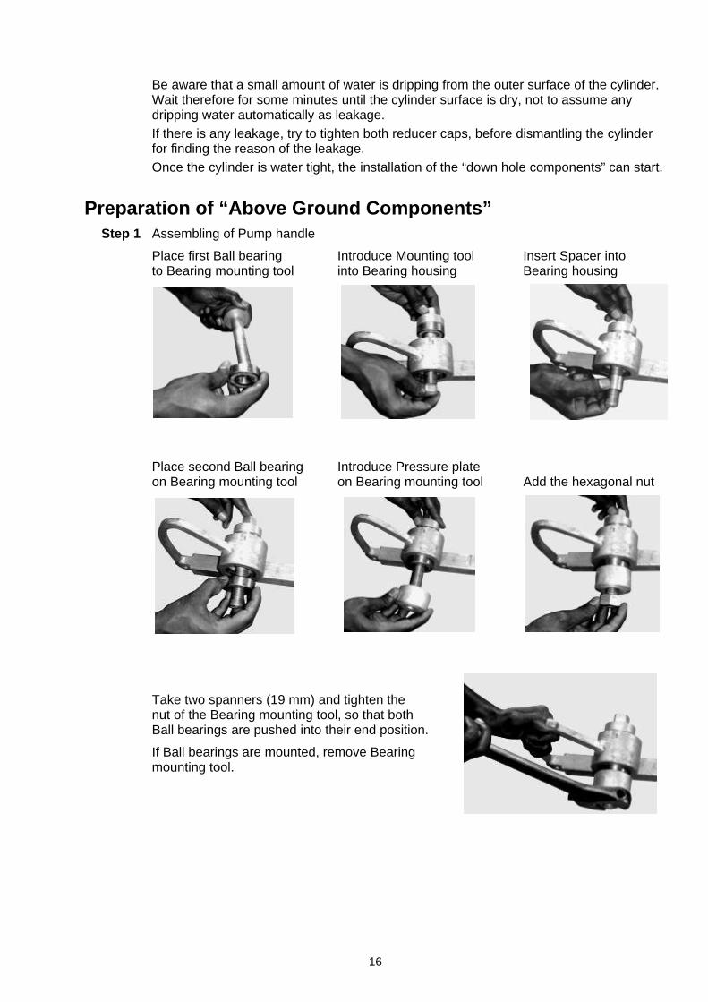
Preparation of “Above Ground Components” Step 1 Assembling of Pump handle
Place first Ball bearing Introduce Mounting tool Insert Spacer into to Bearing mounting tool into Bearing housing Bearing housing
Place second Ball bearing Introduce Pressure plate on Bearing mounting tool on Bearing mounting tool Add the hexagonal nut
Take two spanners (19 mm) and tighten the nut of the Bearing mounting tool, so that both Ball bearings are pushed into their end position.
If Ball bearings are mounted, remove Bearing mounting tool.

17
Step 2 Assembling of Pump head
Introduce the pre-assembled Pump handle into the Pump head assembly and place the Ball bearings near the Axle bushes at the sides of the Pump head.
Knock the handle axle gently into the end position (use a plastic hammer if available).
Introduce Axle washer and If the pump handle is moving smoothly (up- & down), take fasten one nut by hand second nut as a check nut to secure the correct position.

18
Handpump Installation Sequences “Below Ground Components”
Step 1 Take the first riser pipe with pumprod from the logs. Place it horizontally on the pump platform and connect the pumprod to the plunger rod of the cylinder.
Step 2 If the pumprod is tight, apply hemp fibres with grease, sealing liquid or Teflon tape to the pipe thread and screw the riser pipe into the reducer cap of the cylinder.
Step 3 Tighten riser pipe with reducer cap of the
cylinder with two pipe wrenches.
Step 4 Lower the first riser pipe with cylinder into the pump stand (by hand) until the riser pipe protrudes the top face of the pump stand by approx. 50 cm.
Step 5 Introduce the pipe vice and fasten the riser pipe in this position (ideal working height).
Step 6 Take the second riser pipe with pumprod from the logs, connect the pumprods first and then the riser pipe after hemp fibres with grease, sealing liquid or Teflon tape has been applied.

19
Step 7 With the help of the two lifting spanners, the rising main can be lowered after the pipe vice has been opened and removed.
Step 8 Proceed in the same manner until the last pumprod and riser pipe is connected.
Please note: As soon as the rising main is too heavy for being handled with the lifting spanners (5 to 10 pipe lengths), attach the pipe clamp and connect it with the hook of the chain block. Lower the rising main with the help of the chain block on the tripod until the height required (50 cm) for the next connection is reached!
Step 9 At the end of the last riser pipe located in the pipe vice, the water tank will be attached. Therefore take off the last socket of the last riser pipe and re-apply hemp fibres with grease or sealing liquid to the pipe thread.
Step 10 Then the water tank is screwed onto the last pipe end and tighten by hand.
Step 11a (For shallow installations, when rising main is not heavy). With the help of a short piece of riser pipe attached to the socket in the water tank, the entire rising main can be held in place with the help of 2 or 3 lifting spanners. As soon as the pipe vice has been removed, the riser pipe assembly with water tank can be lowered slowly to the pump stand flange.

20
Step 11b (For deep installations with heavy rising main assemblies). With a short piece of rope attached to the hook of the chain block, the water tank can be held securely in position, so that the pipe vice can be removed from the pump stand. Then the water tank with rising main attached can be slowly lowered to the pump stand flange.
Step 12 Turn the water tank so that the spout is pointing into the required direction and tighten it properly to the pump stand with 4 x M12 bolts and nuts. Now the installation of the “above ground components” can start.

21
Installation of “Above Ground Components” Step 1 The protruding last pumprod needs to be
cut to the exact length, so that the plunger connected is not knocking the check valve or the cylinder cap during pump operation.
Step 2 Use a hacksaw for marking the exact
length of the last pumprod (at the top face of the water tank flange).
Step 3 Lift marked pumprod for easy cutting and
fasten with connecting rod vice on the top flange of the water tank. Take a clean piece of cloth and wrap it around the marked rod, in order to prevent metal shavings or oil from falling into the well (contamination).

22
Step 4 Cut last pumprod at the mark.
Step 5 Remove sharp edges and make a nice chamfer prior to threading.
Step 6 Use little oil for cutting the M12 tread (40 mm long). As soon as thread is finished, remove cloth carefully and clean pumprod, vice and pump stand from remaining oil and shavings. Prevent shavings from falling into well.
Step 7 Insert middle flange.

23
Step 8 Allow middle flange to rest on
top of connecting rod vice and fix the check nut on the newly threaded top rod.
Step 9 Screw the chain coupler on the connecting rod threads by hand.
Step 10 Tighten check nut of connecting rod with the chain coupler.
Step 11 Insert chain coupler supporting
tool below the chain coupler. Hold middle flange and remove connecting rod vice.

24
Step 12 Carefully lower the middle flange to
the top of water tank and ensure that all four corners coincide.
Step 13 Hold head assembly in position and insert chain through the hole in the bottom/flange. Lower head on top of middle flange ensuring all four corners to coincide.
Step 14 Tighten head, middle flange and water tank with bolts and nuts.
Step 15 Lift handle up and attach free end of
the chain with high tensile bolt, washer and “Nyloc” nut.

25
Step 16 Tighten “Nyloc” nut.
Step 17 Lower the handle and remove chain coupler supporting tool.
Step 18 Lift handle up and apply grease on the chain.
Step 19 Make sure: • that the connecting rod moves up
and down freely. If it does not, the rod has been bent. Check the rod,
• that the chain coupler is fully engaged on the connecting rod and that the lock nut is tight,
• that the axle nut and lock nut on the handle are tight,
• that the handle axle is firm in place,
• that the “Nyloc” nut has been tightened securely with the chain anchor bolt,
• that all 8 flange bolts and nuts are tight,
• that nothing has been left inside the pump head (tools, cloth etc.).

26
Step 20 Fit inspection cover.
Step 21 Tighten the cover bolt. Step 22 Now the handpump must be operated for first filling of the rising main pipe. Depending on the depth of the cylinder setting, the pump handle has to be operated for many strokes (as an example: an 40 m cylinder setting requires approx. 100 full handle strokes for filling the entire rising main). Step 23 As soon as the water is flowing from the spout, operate the pump for another 100 full strokes. Check whether the water is clean (no oil or dirt). If the water is not clean, the pump operation needs to be continued until the water is acceptable. Step 24 If the water quality is acceptable (optically), the leakage test and the discharge test
must be made (see Page 27). Step 25 If the India Mark II Pump is working as expected, the users must be instructed in “Operation and Maintenance” (O&M) of their pump. Step 26 Don’t forget to fill the “Installation Card” (please see Annex 3).

27
Performance Testing Leakage Test
Testing shall start after a continuous flow of water through the spout has been obtained. The water shall then be collected in a container or bucket for 40 continuous full strokes of the plunger in one minute. Measure the quantity of water collected. Then allow the pump to rest for 30 minutes. Repeat the test and measure the discharge. The difference between the first and the second reading of discharge indicates leakage. If the difference is more than 2 litres, there is an un-acceptable leak and the cause should be investigated.
Another method is to count the number of strokes required before water comes out of the spout after stopping operation for 30 minutes. If the number exceeds 5 strokes until water is flowing, it is an indication that there is an un-acceptable leak and the cause should be investigated.
Leakage mostly occurs because of worn rubber components in the cylinder, leaking rising main joints or severely corroded riser pipes.
Discharge Test
Testing shall start after a continuous flow of water through the spout has been obtained. The water shall then be collected in a container or bucket for 40 continuous full strokes of the plunger in approximately one minute. The water collected should be generally not less than 16 litres. If the discharge is less then 10 litres for 40 strokes, the area mechanic needs to be called for pulling out the rising main pipe and dismantling the cylinder for detecting the reason of the leakage. Another cause for a low discharge could be a perforated or cracked riser pipe due to severe corrosion or a non-tight riser pipe joint.

28
Part 2 Maintenance and Repair Preventive Maintenance
Every pump owner, caretaker or user committee is responsible for preventive maintenance of the water point (handpump including surrounding) and therefore is entitled to receive regular training from the supplier of the handpump. However, the India Mark II Pump is not a VLOM handpump (VLOM = Village Level Operation & Maintenance) and therefore most interventions need to be done with the help of an Pump Mechanic.
Preventive maintenance means regular check-up of the handpump at a fixed time interval and changing of spare parts before they are fully worn. As an example; if the estimated lifetime of a cup seal is one year, the cup seal will be changed after a period of one year even if it is still functional. If during a preventive maintenance check a check valve leakage is noticed, the caretaker must contact the area mechanic. He should carry out repairs in the check valve even though the pump has not broken down. Such interventions help in preventing the sudden failure of the pump.
Time Intervals of Preventive Maintenance Interventions Monthly Checks
(made by the Pump Users) • Check all flange bolts and nuts for tightness (8 off), • Check that handle axle nuts and chain bolt and “Nyloc” nut are tight, • Grease the chain, • Repair holes and cracks on pump platform, • Clean drainage and repair cracks, • Clean the pump surroundings and repair the fence.
Tree monthly Checks
(made by the Pump Users with assistance of a Pump Mechanic) • Check if any fasteners of the pump are missing - if so, add the missing parts. • If any unusual noise is noticed, check reason for the same (worn ball bearings or scratching of
bent pumprods). • Check if the pump stand is shaky during operation. If yes, the stand is loose in the foundation
and contamination of the well can take place. Take corrective measures to improve the foundation.
• Check if there is leakage in the pump. If more than 10 strokes are required before water flows from the spout, it means the pump is leaking beyond an acceptable limit. This needs to be attended to. It may be necessary to replace a rubber seating, a sealing ring or attend to a leaking joint in the rising main. For attending to a defect of all “down hole components” you need the help of a pump mechanic with his special equipment. However, a special leakage test can be conducted by the pump users themselves, prior to the notification to the pump mechanic.
• Carry out a “Leakage- and Discharge Test” (see Page 22). Yearly Replacements
• Dismantle “above ground” and “below ground components”. • Replace rubber seatings (upper valve & lower valve), cup seals (3 off) and sealing rings (3 off). • Replace ball bearings.
Please Note: If one of the replaced components is still in good shape, spare it for emergency replacement (in case a new spare part is not immediately available).

29
Maintenance & Repair of the India Mark II Pump The handpump is like any other mechanical device that needs maintenance to keep it in good working condition. It has been observed that the maintenance in community handpumps is very often “Breakdown-based”. In the absence of preventive maintenance, sudden breakdown of handpumps and disruption in water supply do occur. The danger of abrupt breakdown of the pump can be minimized if preventive maintenance is carried out.
The steps involved in maintenance are to: a) understand the cause for a problem and determine the remedy needed, b) dismantle the pump as necessary, c) assemble the pump after replacing defective components, d) record details in the “Maintenance card” (see Annex 3).
Diagnosis of Handpump Problems To identify the cause of a problem and the remedy needed, please consult the “Trouble Shooting Chart (Annex 1). This chart lists general operational problems, their causes and remedies. Tools required for Handpump Maintenance and Repair The basic tools required for handpump maintenance and repair are:
a) 2 spanners for M10 hexagonal bolts & nuts (C1137) and 2 new Standard spanners (C1xxx), b) 2 spanners for M12 hexagonal bolts & nuts (C1005) and 2 new Standard spanners (C1xxx), c) One 20 litre bucket for discharge test and leaking test.
These tools are required by the pump users for preventive maintenance and are therefore left with the caretaker. All other tools used for maintenance and repair (the same as used for the pump installation) are with the area mechanic (see also Page 13). Materials required for Handpump Maintenance and Repair
The basic materials required for handpump maintenance and repair are the same as listed for the pump installation (see also Page 13). Besides that are required:
a) A small amount of cement, sand and gravel for platform repair, b) Local material to maintain and repair the fence, c) Heavy duty grease for lubricating the chain assembly.
Spare Parts required for Handpump Maintenance and Repair
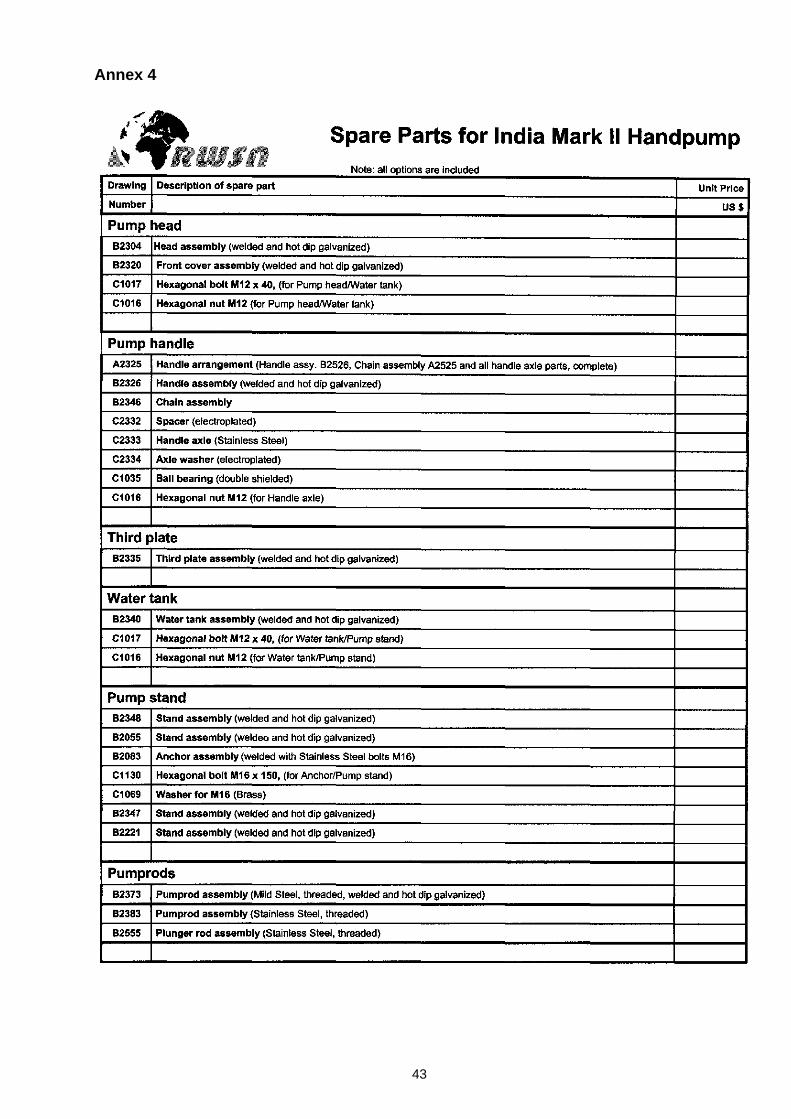
A list of “Fast moving Spare Parts for the India Mark II” is given in Annex 2. A complete list of all India Mark II Pump Spare Parts (including drawing number for ordering) can be found in Annex 4.
Safety Precautions Safety Precautions during Handpump Maintenance and Repair • Never put fingers in moving parts of the pump (between pump head and handle) as this likely to
seriously harm your fingers. • Always use the right tools for the job to avoid accidents and damage of your tools and spares. • Ensure that you communicate with the people you are working with, to ensure that everyone is aware
of what to do. This avoids accidents during repair. • Rising pipes must be held firmly by hand or with rod lifters and clamped securely with the pipe clamp,
ensuring that pipes do not slip down and cause an accident (i.e. squashing of fingers).

30
Dismantling Procedure Sequences Dismantling the “Above Ground Components” Step 1 Loosen pump head cover bolt. Step 2 Remove pump head cover.
Step 3 Lower pump handle. Put chain Step 4 Lift up the pump handle to top
supporting support below the position. Use two open-ended chain assembly. spanners to loosen “Nyloc” nut.

31
Step 5 Remove the “Nyloc” nut anchor bolt Step 6 Loosen and remove bolts and nuts and pull out chain from the handle. connecting head and water tank. Step 7 Lift and remove head assembly. Step 8 Turn flange 90º. Lift connecting rod
The chain will go through hole by holding middle flange and insert in the bottom flange. connecting rod vice.

32
Step 9 Place rods vice on water tank
tank top flange and tighten it. Leave the middle flange resting on the rod vice. Take off the chain support and loosen and remove the chain assembly from top rod.
Step 10 Unscrew check nut and
remove middle flange.
Step 11 Attach the rod lifter (in clockwise direction). Hold the rod lifter firmly, open the vice and remove it
Step 12 Gently lower the pumprod assembly
until it sits on top of the check valve. Unscrew the rod lifter.

33
Step 13 Remove all bolts between water
tank and pump stand. Step 14 Lift the water tank upwards Step 15 Unscrew water tank by turning the
(about 50 cm) and introduce spout by hand. and fasten pipe vice.
Lifting below ground components and water tank with Lifting spanners (see short riser pipe attached to the water tank).
Additional fixation of the riser pipe is required with the help of a pipe wrench.

34
Dismantling the “Below Ground Components” The below ground components of the India Mark II Pump can be dismantled (and re-installed) with two Lifting spanners different systems:
a) For pump installations between 10 to 30 m, the rising main pipe with pumprods and the cylinder can be lifted with 2 or 3 specially designed Lifting spanners. Therefore a short piece of a threaded riser pipe can be connected to the thread of the water tank, so that the Lifting spanners can be applied.
b) For pump installations between 30 to 50 m, Tripod with Chain block the weight of the below ground components is increasing and therefore a Tripod with a Chain block (or pulley wheel with rope) can be used for lifting the rising main pipe with pumprods and cylinder. For getting a secure grip on the rising main, a Pipe clamp needs to be attached and a piece of rope is used to attach the pipe with pipe clamp to the hook of the lifting device (chain block). Pipe clamp Pipe vice After lifting the below ground components for a complete pipe length (3 m), a Pipe vice is used to fix the riser pipe in position when the retrieved riser pipe and the pumprod are getting unscrewed.
The following description is for dismantling the below ground components with a tripod & chain block:
Step 1 Attach pipe clamp and connect it with a piece of rope to the hook of the chain block.
Step 2 Operate chain block until the chain is tight and then open the pipe vice slowly and remove it.
Step 3 Lift rising main pipe / pumprods and cylinder until the next pipe socket is about 0.5 m above Riser pipe with pipe clamp & attached hook the top flange of pump stand.
Step 4 Introduce the pipe vice and clamp the rising main securely.
Step 5 Remove the pipe clamp and open the protruding riser pipe with two pipe wrenches.
Step 6 Lift the unscrewed riser pipe by hand, so that the pumprod connection is visible.
Step 7 Unscrew the pumprod connection and place the rods and pipes separately on a clean place.
Step 8 Attach pipe clamp to the remaining rising main pipe (close to the pipe vice).
Step 9 Connect pipe clamp to the hook of the chain block and tighten the chain.
Step 10 Continue with Step 1 to Step 9 until the whole Pumprod opening while holding riser pipe rising main, pumprods and cylinder are retrieved.

35
Please note: For shallow installations where the total weight of the rising main, pumprods and cylinder is not so heavy, dismantling (and also re-installation) of the below ground components can be done easily with the Lifting spanners.
Lifting spanner in operation
Step 11 The last riser pipe can then be removed from the cylinder.
Removing last riser pipe from the cylinder
Step 12 Then the last pumprod gets disconnected from the plunger rod.
Disconnecting pumprod from plunger rod Step 13 From the cylinders, both caps can be opened and the plunger & check valve removed. Step 14 The plunger and the check valve can also be dismantled to check or replace worn parts
(cup seals and rubber seatings).
Cylinder parts of the India Mark II Pump
Step 15 Once the defective pump components have been replaced and the pump is re-assembled again, explanations needs to be given to the pump users, about what the problem was and why the break down might has happened.

36
Maintenance of Pump Surrounding Handpumps with platforms offer a good protection, because they seal off the well from external sources of contamination. However, even when handpumps are fitted, contaminations can still pollute the well through:
a) Cracked platforms and drainage channels, b) Stagnant water near the well, c) Animals (and human) excrements too close to the well (no fence), d) Waste and other sources of contamination too close to the well.
It is the important task of the Handpump Caretaker to: a) Check the platform for cracks and do the necessary repair, b) Eliminate stagnant water by filling the dents and holes with earth, c) Maintain the fence around the water point, so that no animals have access, d) Keep the surroundings clean and tidy at all times, e) Instruct the pump users how to use the pump and how to keep the pump
surroundings clean.
(See also chapter Well Siting and Hygiene Education and Water Supply on Page 7.) Platform Maintenance Tools
The following tools are recommended for regular maintenance of platforms: a) Hammer and chisel for opening cracks and for taking off weathered and bad quality cement, b) Bucket - for measuring cement, sand (gravel) and water, c) Shovel - for mixing the concrete, d) Trowel - for applying the concrete mix.
Instructions for mixing Concrete for Platform Repair
Mixing of Concrete (for large repair work) As measurement can be used a bucket, shovel or trowel, depending on how much concrete is needed.
1. Fill 2 measurements of sand and pour it on a hard smooth surface preferably on the platform, 2. Fill 1 measurement of cement and pour it on to the sand, 3. Mix the cement and sand until the mixture has an uniform colour, 4. Fill 3 measurement of gravel and pour it onto the sand/cement mixture (gravel can be made by
crushing rock with a hammer), 5. Turn the mixture over three times, 6. Form a crater in the middle of the dry mixture add water in the crater, being careful not to add too much
water. If you need water you can always add some more later, 7. Carefully turn the concrete on the side of the crater into the water. Don't let the water spill over or it will
wash away the cement, 8. Turn the pile over until it is moist and uniformly mixed with the water; the concrete should be dense and
just moist, 9. If the concrete is too dry, make another crater in the middle of the mixture and add a little more water, 10. If the concrete mix is too wet, add more cement, sand and gravel, do not add only cement or sand. 11. Remember that the Curing time for the concrete is seven (7) days, therefore the platform has to be
protected for seven days and the new concrete has to be kept wet throughout the seven days in order to receive the required strength.

37
Part 3 Recording of Interventions It is advisable to collect and record any data of a well, starting from digging or drilling, platform construction, installation of a handpump including all maintenance and repair interventions during the lifetime of the handpump and the well (like a “log-book” on a ship).
Besides Installation and Monitoring details, make the necessary entries of Maintenance and Repair in the documents of each pump. The information to be recorded will include date of breakdown, date of repair, nature of complaint, parts replaced and kind of repair or any other important observations. (see also the Installation Card, the Maintenance Card and the Monitoring Card in Annex 3).
Mixing of Mortar (for small repair work) As measurement can be used a bucket, shovel or trowel, depending on how much concrete is needed.
1. Fill 2 measurements of sand and pour it on a hard smooth surface preferably on the platform,
2. Fill 1 measurement of cement and pour it on to the sand, 3. Mix the cement and sand until the mixture has an uniform colour, 4. Form a crater in the middle of the dry mixture add water into the crater, being careful not to add too
much. If you need more water you can always add some more later, 5. Carefully turn the mortar on the side of the crater into the water. Don't let the water spill over or it
will wash away the cement, 6. Turn the pile over until it is moist and uniformly mixed with the water; the mortar should be dense
and just moist, 7. If the mortar is too dry, make another crater in the middle of the mixture and add a little more
water, 8. If the mortar mix is too wet, add more cement and sand. 9. Remember that the Curing time for the masonry work is seven (7) days, therefore the platform
has to be protected for seven days and the new masonry work has to be kept wet throughout the seven days in order to receive the required strength.

38
Annexes Annex 1 Trouble Shooting
Trouble Possible Causes Remedy Who Worn cup-seals Pull out rising main, open cylinder
and replace all worn cup-seals Pump mechanic
Water level dropped below cylinder
Add more riser pipes and pumprods
Pump mechanic
Broken chain Replace chain Pump users Check valve jammed (not closing)
Pull out rising main, open cylinder, check function of check valve and make needed replacements
Pump mechanic
Pump works easily, but no flow of water
Pumprod disconnected Pull out rising main and join disconnected pumprod
Pump mechanic
Check valve leaking Pull out rising main, open cylinder, check leaking of check valve and make replacements if required
Pump mechanic
Worn sealing rings Pull out rising main, check sealing rings and make replacements if needed
Pump mechanic
Worn cup-seals Pull out rising main, open cylinder and replace all worn cup-seals
Pump mechanic
Delayed flow or little flow of water
Damaged rising main (leaking pipe threads or severe pipe corrosion)
Pull out rising main, check all riser pipes and make replacements if required
Pump mechanic
Plunger jammed inside cylinder
Pull out rising main, open cylinder, check size of plunger and cylinder and replace wrong or defective components
Pump mechanic
Folding of chain during down-stroke
Top rod too long, plunger is sitting on top of the check valve
Take off pump head, check correct length of pumprod assembly and trace top rod if needed
Pump mechanic
Lack of grease on chain
Grease chain Pump user
Worn ball bearings Replace ball bearings Pump mechanic
Noise during pump operation
Shaky foundation Check foundation and make necessary repair
Pump mechanic
Loose handle axle nuts Tighten handle axle nuts Worn or damaged spacer
Replace spacer
Worn or damaged axle Replace handle axle Pump mechanic
Worn ball bearings Replace ball bearings Pump mechanic
Shaky pump handle
Bearings loose in bearing house
Replace handle assembly (for possible repair)
Pump mechanic

39
Annex 2 List of Fast Moving Spare Parts Below are the fast moving spare parts for the India Mark II Handpump. Preferred number of parts available is indicated. As soon as one part is used, the process of obtaining a new replacement should be initiated. For regular maintenance • Grease Multi purpose – for greasing chain assembly 1 can • Grease (and hemp fibres) or sealing compound for riser pipe connections 1 can For head assembly • Hexagonal bolt for pump head and water tank - M12 x 40 mm 8 off • Hexagonal nut for pump head, water tank and handle axle - M12 18 off • Hexagonal bolt for inspection cover - M12 x 20 mm 1 off • Washer for inspection cover - to suit M12 bolt 1 off For handle assembly • Hexagonal bolt for chain assembly – M10 x 40 mm 1 off • Hexagonal lock nut for chain assembly – M10 (“Nyloc”) 1 off • Washer for handle axle - drawing C2334 1 off • Spacer for handle axle – drawing C2332 1 off • Ball bearing – drawing C1035 2 off For cylinder parts • Cup seal for plunger assembly – drawing C2359 2 off • Rubber seating – drawing C2360 1 off • Rubber seating – drawing C2364 1 off • Sealing ring – drawing C2354 3 off Please note: A complete list of all spare parts of the India Mark II Handpump can be found in Annex 4.

40
Annex 3

41

42
43
Annex 4

44
Please note: Due to a new Standard for threaded bolts, the hexagonal head sizes require different spanner sizes:
a) C1152 Spanner size for M10 bolts are 16 mm, b) C1153 Spanner size for M12 bolts are 18 mm.
Therefore, pump manufacturers are requested to supply the new spanner sizes in addition to the existing spanners in order to avoid mixing of different sizes during the transitional period (10 years).