![YMDTIME YMD CANCEL FE-46/X-42/X-41...QUITTE MENU CONF OK REGLAGE 2 Appuyez sur la touche B. 3 Utilisez kl pour sélectionner [W], puis appuyez sur la touche B. 4 Utilisez klmn pour](https://static.fdocuments.in/doc/165x107/5f6615fdfea3966c5167fc7e/ymdtime-ymd-cancel-fe-46x-42x-41-quitte-menu-conf-ok-reglage-2-appuyez-sur.jpg)
Installation Instructions Use and Care Information ... · Use and Care Information Instructions...
32
AGIO24PR300-B AGIO30PR300-B Installation Instructions Use and Care Information Instructions d'installation Utilisez et d'entretien AGIO 24" / 30"
-
Upload
phungkhanh -
Category
Documents
-
view
221 -
download
2
Transcript of Installation Instructions Use and Care Information ... · Use and Care Information Instructions...
AGIO24PR300-BAGIO30PR300-B
Installation InstructionsUse and Care Information
Instructions d'installationUtilisez et d'entretien
AGIO 24" / 30"
2
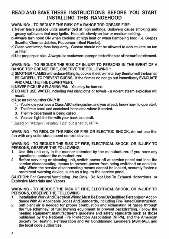
READ AND SAVE THESE INSTRUCTIONS BEFORE YOU START INSTALLING THIS RANGEHOOD
WARNING: - TO REDUCE THE RISK OF A RANGE TOP GREASE FIRE: a) Never leave surface units unattended at high settings. Boilovers cause smoking and
greasy spillovers that may ignite. Heat oils slowly on low or medium setting.
Suzette, Cherries Jubilee, Peppercorn Beef Flambé). c) Clean ventilating fans frequently. Grease should not be allowed to accumulate on fan
d) Use proper pan size. Always use cookware appropriate for the size of the surface element.
WARNING: - TO REDUCE THE RISK OF INJURY TO PERSONS IN THE EVENT OF A RANGE TOP GREASE FIRE, OBSERVE THE FOLLOWING*:
AND CALL THE FIRE DEPARTMENT. b) NEVER PICK UP A FLAMING PAN - You may be burned. c) DO NOT USE WATER, including wet dishcloths or towels - a violent steam explosion will
result.d) Use an extinguisher ONLY if: 1. You know you have a Class ABC extinguisher, and you already know how to operate it.
* Based on "Kitchen Firesafety Tips" published by NFPA
WARNING - TO REDUCE THE RISK OF FIRE OR ELECTRIC SHOCK, do not use this fan with any solid-state speed control device.
WARNING - TO REDUCE THE RISK OF FIRE, ELECTRICAL SHOCK, OR INJURY TO PERSONS, OBSERVE THE FOLLOWING: 1. Use this unit only in the manner intended by the manufacturer. If you have any
questions, contact the manufacturer.2. Before servicing or cleaning unit, switch power off at service panel and lock the
service disconnecting means to prevent power from being switched on acciden-tally. When the service disconnecting means cannot be locked, securely fasten a prominent warning device, such as a tag, to the service panel.
CAUTION: For General Ventilating Use Only. Do Not Use To Exhaust Hazardous or Explosive Materials and Vapors.
WARNING - TO REDUCE THE RISK OF FIRE, ELECTRICAL SHOCK, OR INJURY TO PERSONS, OBSERVE THE FOLLOWING: 1. -
dance With All Applicable Codes And Standards, Including Fire-Rated Construction. 2.
heating equipment manufacturer's guideline and safety standards such as those
the local code authorities.

3
ALL WALL AND FLOOR OPENINGS WHERE THE RANGEHOOD IS INSTALLED MUST BE SEALED.
This rangehood requires at least 24" of clearance between the bottom of the rangehood and the cooking surface or countertop. This hood has been approved by UL at this distance from the cooktop. Overhead cabinets on both sides of this unit must be a minimum of 18" above the cooking surface or countertop. Consult the cooktop or range installation instructions given by the manufacturer before making any cutouts. MOBILE HOME INSTALLATION The installation of this rangehood must conform to the Manufactured Home Construction and Safety Standards, Title 24 CFR, Part 3280 (formerly Federal Standard for Mobile Home Construction and Safety, Title 24, HUD, Part 280). See Electrical Requirements.
• Venting system MUST terminate outside the home.• DO NOT terminate the ductwork in an attic or other enclosed space.• DO NOT use 4" laundry-type wall caps.• Flexible-type ductwork is not recommended.• DO NOT
WARNING!
Cold Weather installations
nonmetallic thermal break should be installed to minimize conduction of outside temperatures as part of the vent system. The damper should be on the cold air side of the thermal break. The break should be as close as possible to where the vent system enters the heated portion of the house.
VENTING REQUIREMENTSDetermine which venting method is best for your application. Ductwork can extend either through the wall or the roof.
performance. The size of the ductwork should be uniform. Do not install two elbows together. Use
around the cap.
Flexible ductwork is not recommended. Flexible ductwork creates back pressure and air turbulence that greatly reduces performance.
Do not cut a joist or stud unless absolutely necessary. If a joist or stud must be cut, then a supporting frame must be constructed.
WARNING - To Reduce The Risk Of Fire, Use Only Metal Ductwork.
not vent exhaust air into spaces within walls or ceilings or into attics, crawl spaces, or garages.
3. When cutting or drilling into wall or ceiling, do not damage electrical wiring and other hidden utilities.
4. Ducted fans must always be vented to the outdoors.

4
• Electrical ground is required on this rangehood.• If cold water pipe is interrupted by plastic, nonmetallic gaskets or other materials, DO
NOT use for grounding.• DO NOT ground to a gas pipe.• DO NOT have a fuse in the neutral or grounding circuit. A fuse in the neutral or
grounding circuit could result in electrical shock.
properly grounded.
WARNING

5
RANGEHOOD DIMENSIONS
Min. 24"
1"
12"1 3/8"
1 7/8"
1 1/2"
2 5/8"
23 5/8" - 29 7/8"
1"2"
7 1/2"
6"
8 1/2"
47 "

6
MAIN PARTS
ComponentsRef. Qty. Product Components1 1 Hood Body, complete with: Controls, Light, Filters, Blower.2 1 Power cord 3 1 Damper
Ref. Qty. Installation Components12e 4 Screws (1/8"x1/4")12f 4 Screws (1/8"x5/8")
Qty. Documentation 1 Instruction Manual
Available Accessories
Activated Charcoal Filter sku #; FILTER3
Kit frontal panel # AGTRIM24SSKit frontal panel # AGTRIM30SSKit frontal panel # AGTRIM24BKKit frontal panel # AGTRIM30BKKit frontal panel # AGTRIM24WHKit frontal panel # AGTRIM30WH
12e
1
12f
3
2

7
Choose your ducting method
Ducting method
Horizontal Vertical
VERTICAL DUCTINGREAR DUCTING
23 5/8" - 29 7/8"
3 1/2"1 7/8"
10 3/4"
23 5/8" - 29 7/8"
3 1/2"
9 3/8"10 3/4"

8
1
2
1. Disconnect and move freestanding range from cabinet opening to provide easier access to upper cabinet and rear wall. Put a thick, protective covering over cooktop, set-in range or countertop to protect from damage or dirt.
2. Determine and clearly mark with a pencil the center line of the cabinet on the wall and on the underside of the cabinet where the rangehood will be installed.
1. Remove the unit from the carton and
sure to cover the surface toprevent accidental damage. Remove all parts including the Backdraft Damper, Screws, and Literature Package before discarding the carton.2. unit and set aside. The rangehood is shipped from the factory with the backdraft damper attached inside. Using a Phillips head screwdriver, remove the backdraft damper by loosening the screw marked with a red dot on top of the rangehood.3. Before installing, the rangehood must be adjusted for venting. For ductless installations, read the following section which discusses special requirements for these installations before continuing.
Installation Instructions
8 1/2"
1"1"
23 5/8" - 29 7/8"
2"
3. The Agio attaches to the cabinet by four black screws. Mark the cabinet and insert the screws (12f)the screws.
4. Determine the proper cutouts for the ductwork. Make all necessary cuts in the walls or cabinets for the ductwork. Install the ductwork before mounting the rangehood.

9
3
4
5
For Horizontal or Vertical ducting, the respective exhaust knockout must be removed. Each knockout is attached to the rangehood by four points. Us-
knife, remove the exhaust knockout. Save this plate as it must be used to block the ductless exhaust grill. Figure shows the location of the knockouts for both horizontal and vertical. ONLY ONE must be removed.
Remove the central support and control box by removing the screws
to remove the blower to perform this operation.
Attach the cover behind the exhaust grate with two silver screws 12e sup-plied with the rangehood.
10
6
7
8
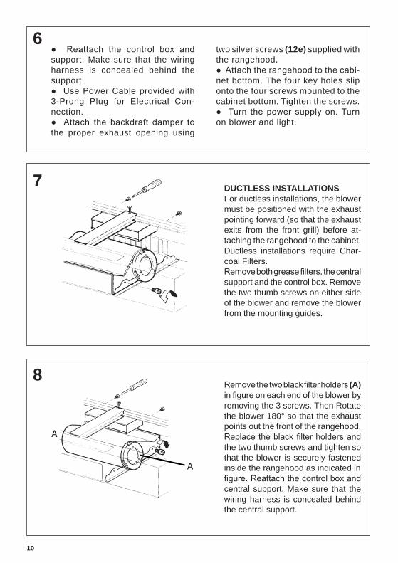
support. Make sure that the wiring harness is concealed behind the support.
3-Prong Plug for Electrical Con-nection.
the proper exhaust opening using
two silver screws (12e) supplied with the rangehood.
-net bottom. The four key holes slip onto the four screws mounted to the cabinet bottom. Tighten the screws.
on blower and light.
DUCTLESS INSTALLATIONSFor ductless installations, the blower must be positioned with the exhaust pointing forward (so that the exhaust exits from the front grill) before at-taching the rangehood to the cabinet.Ductless installations require Char-coal Filters.
support and the control box. Remove the two thumb screws on either side of the blower and remove the blower from the mounting guides.
(A)
removing the 3 screws. Then Rotate the blower 180° so that the exhaust points out the front of the rangehood.
the two thumb screws and tighten so that the blower is securely fastened inside the rangehood as indicated in
central support. Make sure that the wiring harness is concealed behind the central support.
A
A

11
9For ductless installations, Charcoal Filters are required and must be
to both ends of the blower.
“When used in recirculation mode, to Reduce the Risk of Fire and Shock use only conversion kit Model FILTER3.”
10 11
previously.
For Non-Ducted Recirculation Option
Required Activated Charcoal Filter Accessory - sku # - FILTER3 (purchased separately)
each side of the blower. Press the charcoal
the front of the insert hood) until it locks into place. Turn counterclockwise (towards the back of the insert hood) to remove.

12
13 ELECTRICAL INSTALLATION WITH CONNECTION CABLE
Max. 33 7/16”
GROUNDING INSTRUCTIONS This appliance must be grounded. In the event of an electrical short circuit, grounding reduces the risk of electric shock by providing an escape wire for the electric current. This appliance is equipped with a cord having a ground-ing wire with a grounding plug. The plug must be plugged into an outlet that is properly installed and grounded.WARNING - Improper grounding can result in a risk of electric shock.
grounding instructions are not com-pletely understood, or if doubt exists as to whether the appliance is properly grounded.
12
CUSTOMIZING YOUR RANGEHOODThe front strip of the rangehood can be customized. The front strip is attached to the rangehood by three recessed screws and three key hole slots on the back side of the strip.It is necessary only to remove the three lower screws to remove the front strip. The top screws will slide out of the key holes once the three lower screws are removed.
The front strip dimensions are shown above. If you wish to keep the frame of the front panel and only replace the glass panel, the dimensions follow: Height = 5 11/16", Depth = 1/8", Width = 29 11/16" (for 30" model) 23 5/8" (for 24" model).
5 7/8"
13/16"23 5/8" - 29 7/8"
Rangehood Body
FrontStrip
Three Screws
Do not use an extension cord. If the power
electrician install an outlet near the appliance.

13
USE AND CARE INFORMATION
L. Light On/Off SwitchOn/Off switch for the light. Moving the switch to the 1 Position turns the light On. Moving the switch to the 0 Position turns the light Off.
M. Blower On/Off SwitchOn/Off switch for the blower. Moving the switch to the 1 Position turns the blower On. Moving the switch to the 0 Position turns the blower Off.
S. Blower Speed SwitchControls blower speed. Moving the switch to the 1 Position turns the blower on LOW. Moving the switch to the 2 Position turns the blower on MEDIUM. Moving the switch to the 3 Position turns the blower on HIGH.
I. Operation Indicator LightRed light will be on when the rangehood is operating.
MS. MicroswitchWhen the front panel of the rangehood is closed, the rangehood will turn off by a microswitch. This turns the rangehood On and Off without adjusting the switches for the Light or Blower and it remembers the last speed setting.
Cleaning
the dishwasher. Clean exterior surfaces with hot soapy water. Using abrasives and scouring
For Best ResultsThis rangehood system is designed to remove smoke, cooking vapors and odors from the cooktop area. For Best Results Start the rangehood several minutes before cooking to develop
all smoke and odors from the kitchen.
L M MS I S

14
solution or washed in the dishwasher. They should be cleaned every 2 months, or more frequently if use is par-ticularly heavy. •
the unit and at the same time pulling downward.• -
color over time, this will have absolutely no effect on its
• Replace, taking care to ensure that the handle faces forward.
•
Replacing Activated Charcoal Filter
The Activated Charcoal Filters are not washable and cannot be regenerated, and should be replaced approximately every 4 months of operation, or more frequently with heavy usage.• -
wards) until it unlocks from the motor housing and pull off sideways.
• of the blower and push it inward. Then turn the charcoal
Replacing the two 35W Halogen GU10 bulbs
• Turn off electrical supply before replacing bulbs, and make sure bulbs are cool to touch before proceeding.
screwdriver by levering it down from under the metal ring.• After the snap-on lamp cover is down remove the halogen
lamp at the base and turn slightly to the left and the pull out from the connector and turn slightly to the left.
• Replace the lamp with a new one of the same type, making sure that you insert the two pins properly into the housings on the lamp holder.
• Replace the snap-on lamp cover. • Once the bulb pins are in place turn slightly to the right
to secure.

15
Wiring Diagram

16
January 4, 2016
FABER CONSUMER WARRANTY & SERVICE
All Faber products are warranted against any defect in materials or workmanship for the original purchaser
for a period of 1 year from the date of original purchase (requires proof of purchase). This warranty covers
labor and replacement parts. Faber, at its option, may repair or replace the product or components
necessary to restore the product to good working condition. To obtain warranty service, contact the dealer
from whom you purchased the range hood, or the local Faber distributor. If you cannot identify a local Faber
distributor, contact us at (508) 358-5353 for the name of a distributor in your area.
The following is not covered by Faber's warranty: 1. Service calls to correct the installation of your range hood, to instruct you how to use your range hood, to
replace or repair house fuses or to correct house wiring or plumbing.
2. Service calls to repair or replace range hood light bulbs, fuses or filters. Those consumable parts are
excluded from warranty coverage.
3. Repairs when your range hood is used for other than normal, single-family household use.
4. Damage resulting from accident, alteration, misuse, abuse, fire, flood, acts of God, improper installation,
installation not in accordance with electrical or plumbing codes or Faber documentation, or use of products
not approved by Faber.
5. Replacement parts or repair labor costs for units operated outside the United States or Canada, including
any non-UL or C-UL approved Faber range hoods.
6. Repairs to the hood resulting from unauthorized modifications made to the range hood.
7. Expenses for travel and transportation for product service in remote locations and pickup and delivery
charges. Faber range hoods should be serviced in the home.
THIS WARRANTY DOES NOT ALLOW RECOVERY OF INCIDENTAL OR CONSEQUENTIAL DAMAGES, INCLUDING, WITHOUT
LIMITATION, DIRECT, INDIRECT, INCIDENTAL, SPECIAL OR CONSEQUENTIAL DAMAGES, PERSONAL INJURY/WRONGFUL
DEATH OR LOST PROFITS FABER WARRANTY IS LIMITED TO THE ABOVE CONDITIONS AND TO THE WARRANTY PERIOD
SPECIFIED HEREIN AND IS EXCLUSIVE. EXCEPT AS EXPRESSLY SPECIFIED IN THIS AGREEMENT, FABER DISCLAIMS ALL
EXPRESS OR IMPLIED CONDITIONS, REPRESENTATIONS, AND WARRANTIES INCLUDING, WITHOUT LIMITATION, ANY
IMPLIED WARRANTIES OF MERCHANTABILITY OR FITNESS FOR A PARTICULAR PURPOSE.
This warranty gives you specific legal rights that may vary from state to state.
Model#: ______________________________ Serial #: _____________________________

17
VEUILLEZ LIRE ET CONSERVER LA PRÉSENTE NOTICE AVANT DE COMMENCER L'INSTALLATION DE LA HOTTE DE CUISINE
AVERTISSEMENT:-POUR RÉDUIRE LE RISQUE D'UN FEU DE GRAISSE SUR LA TABLE DE
a) Ne laissez jamais sans surveillance les éléments de la surface de cuisson à température élevée. Les bouillonnements excessifs peuvent provoquer de la fumée et les débordements de graisse
b) Assurez-vous de toujours mettre en marche le ventilateur de la hotte lorsque vous cuisinez
c) Nettoyez régulièrement les ventilateurs d'aspiration. Assurez-vous de ne pas laisser de la graisse
de cuisine de la taille adaptée à celle de l'élément chauffant.
a) ÉTOUFFEZ LES FLAMMES à l'aide d'un couvercle hermétique, d'une plaque à biscuits ou d'un plateau métallique, puis éteignez le brûleur. FAITES ATTENTION AUX BRÛLURES. Si le feu ne s'éteint pas immédiatement, QUITTEZ LES LIEUX ET APPELEZ LES POMPIERS.
b) NE PRENEZ JAMAIS UNE CASSEROLE EN FLAMME - Vous pourriez vous brûler. c) N'UTILISEZ JAMAIS DE L'EAU, ni un linge à vaisselle ou un torchon mouillé, pour éteindre le feu.
Cela pourrait provoquer une violente explosion de vapeur.
mode d'emploi. 2. Le feu est de faible intensité et se limite à l'endroit où il a démarré. 3. Les pompiers ont déjà été appelés.
AVERTISSEMENT - POUR RÉDUIRE LE RISQUE D'INCENDIE OU DE CHOC ÉLECTRIQUE, n'utilisez jamais ce ventilateur en association avec un dispositif de réglage de vitesse à semi-conducteurs.
AVERTISSEMENT - POUR RÉDUIRE LES RISQUES D'INCENDIE, DE CHOC ÉLECTRIQUE OU DE
1. Utilisez cet appareil uniquement de la façon prévue par le fabricant. Pour toute question, com-muniquez avec le fabricant.
2. Avant de procéder à l'entretien ou au nettoyage de l'appareil, coupez l'alimentation au niveau du panneau électrique et verrouillez-le pour vous assurer que l'électricité n'est pas rétablie accidentel-
façon ferme et bien visible un avis de danger, par exemple à l'aide d'une étiquette sur le panneau.
pour l'aspiration de vapeurs ou de matériaux dangereux ou explosifs.
AVERTISSEMENT - POUR RÉDUIRE LES RISQUES D'INCENDIE, DE CHOC ÉLECTRIQUE OU DE
1. conformément à tous les codes et normes en vigueur, incluant ceux concernant la construction à l'épreuve du feu.
2. cheminée des appareils à combustion, une bonne aération est nécessaire pour éviter le refou-lement. Respectez les lignes directrices fournies par le fabricant du matériel chauffant, ainsi que
États-Unis, ainsi que les codes en vigueur dans votre région.

18
Un espace libre d'au moins 24 " est requis entre le bas de la hotte et la surface de
d'installation de la surface de cuisson ou de la hotte fournie par le fabricant avant de pratiquer des ouvertures. INSTALLATION DANS UNE MAISON MOBILE L'installation
norme Federal Standard for Mobile Home Construction and Safety, Title 24, HUD).
• NE FAITES PAS• N'UTILISEZ PAS
• N'ENTRAVEZ PAS• Le non-respect des exigences en matière de ventilation pourrait entraîner un incendie.
AVERTISSEMENT!
Installation dans les climats froids
CRITÈRES DE VENTILATION
passer par le mur ou le toit.
-
Il n'est pas recommandé d'utiliser des conduits flexibles. Les conduits flexibles provoquent une contre-pression et de la turbulence qui diminuent grandement l'efficacité de l'appareil.
AVERTISSEMENT - Pour réduire le risque d'incendie, utilisez uniquement des conduits métalliques.ATTENTION - Pour réduire le risque d'incendie et pour évacuer adéquatement l'air, assurez-vous
l'intérieur des murs ou du plafond, ou encore à l'intérieur d'un grenier, d'une galerie technique ou d'un garage.
3. Lorsque vous faites une ouverture ou percez dans un mur ou le plafond, veillez à ne pas
4.
19
AVERTISSEMENT

20
DIMENSIONS DE LA HOTTE
Min. 24"
1"
12"1 3/8"
1 7/8"
1 1/2"
2 5/8"
23 5/8" - 29 7/8"
1"2"
7 1/2"
6"
8 1/2"
47 "

21
ComposantsRéf. Qté Composants du produit1 1 Bâti de la hotte, avec :
ventilateur.2 1 Câble d'alimentation 3 1 Registre
Réf. Qté Composants d'installation12e 4 Vis (1/8"x1/4")12f 4 Vis (1/8"x5/8")
Qté Documentation 1 Mode d'emploi
PIÈCES PRINCIPALES
Accessoires disponibles
Filtre à charbon actif, no d'article FILTER3
Trousse panneau frontal # AGTRIM24SSTrousse panneau frontal # AGTRIM30SSTrousse panneau frontal # AGTRIM24BKTrousse panneau frontal # AGTRIM30BKTrousse panneau frontal # AGTRIM24WHTrousse panneau frontal # AGTRIM30WH
12e
1
12f
3
2

22
Choisissez la méthode de canalisation
Préparation de l’armoire
Horizontal Vertical
CONDUIT VERTICALCONDUIT HORIZONTAL
23 5/8" - 29 7/8"
3 1/2"1 7/8"
10 3/4"
23 5/8" - 29 7/8"
3 1/2"
9 3/8"10 3/4"

23
1
2
1. Débrancher et déplacer la cuisinière de
aux armoires supérieures et au mur ar-rière. Placer un recouvrement épais sur la plaque de cuisson, la cuisinière encastrée ou le dessus du comptoir pour protéger des dommages et de la poussière.
2. Déterminer et marquer clairement, à l’aide d’un crayon, la ligne centrale sur le mur et sur le côté inférieur de l’armoire où la hotte sera installée.
1. Retirer l’appareil de la boîte et le déposer sur une surface plate pour l’as-semblage. Couvrir la surface pour éviter tout dommage accidentel. Retirer toutes les pièces incluant 1 registre à clapet, les vis, et le nécessaire d'instructions avant de jeter la boîte.2. de l’appareil et les mettre de côté. La hotte est expédiée de l’usine avec un registre
un tournevis Phillips, retirer le registre en dévissant les vis marquées d’un point rouge sur le dessus de la hotte.3. Avant l’installation, la hotte doit être ajustée pour la ventilation. Pour les installations sans conduit, lire la section suivante qui traite des exigences spé-ciales pour ce type d’installation avant de continuer.
Installation de la hotte
8 1/2"
1"1"
23 5/8" - 29 7/8"
2"
3. insérer les vis (12f)pas serrer les vis.
4. Déterminer l’emplacement de la coupe pour le conduit. Faire toutes les coupes néces-saires dans les murs ou les armoires pour le conduit. Installer le conduit avant de poserla hotte.

24
3
4
5
Pour les conduits horizontaux et verticaux, la pastille enfonçable doit être enlevée. Chaque pastille est maintenue à la hotte en quatre points. Utiliser un tournevis à lame plate ou un couteau tout usage, retirer la pastille enfonçable. Conserver cette pièce car elle doit servir à maintenir en place la grille d’évacuation sans
-ment des pastilles enfonçables pour les modèles horizontaux et verticaux. UNE SEULE doit être enlevée.
Retirer le support central et la boîte de contrôle en enlevant les vis tel qu’il
nécessaire de retirer le ventilateur.
Fixer le couvercle derrière la grille d’évacuation à l’aide de deux vis argenté 12e fournies avec la hotte.

25
6
7
8
et le support. S’assurer que le fil conducteur soit caché derrière le support.
avec une fiche trois broches pour le branchement électrique.
d’évacuation appropriée à l’aide
de deux vis argenté (12e) fournies avec la hotte.
Les quatre fentes à trous s’insèrent sur les quatre vis fixées au bas de l’armoire. Serrer les vis.
Mettre en circuit le ventilateur et la lumière.
INSTALLATIONS SANS CONDUITLes installations sans conduit re-quièrent le nécessaire sans conduit. Le ventilateur doit être placé de façon à ce que l’évacuation se fasse vers l’avant (l’évacuation sera faite par la
à l’armoire. Les installations sans conduit requièrent un nécessaire des Filtres au Charbon.
support central et le boîtier de com-mande. Enlever les deux vis à oreilles des deux côtés du ventilateur et retirer le ventilateur des rails de montage.
Enlevez les deux supports noirs de (A) -
trémité du ventilateur en enlevant les 3 vis. Tourner le ventilateur sur 180º de façon à ce que l’évacuation se fasse vers l’avant de la hotte. Remplacez
les deux écrous à oreilles de chaque côté du ventilateur et serrer de façon à
-ment à l’intérieur de la hotte, tel qu’il
boîte de contrôle et le support central.
derrière le support central.
A
A
26
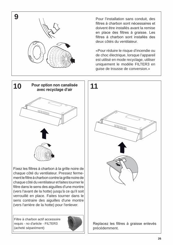
9 Pour l’installation sans conduit, des
doivent être installés avant la remise
deux côtés du ventilateur.
«Pour réduire le risque d’incendie ou de choc électrique, lorsque l’appareil est utilisé en mode recyclage, utiliser uniquement le modèle FILTER3 en guise de trousse de conversion.»
10 11
précédemment.
Pour option non canaliséeavec recyclage d'air
Filtre à charbon actif accessoirerequis - no d'article - FILTER3(acheté séparément)
chaque côté du ventilateur. Pressez ferme-
chaque côté du ventilateur et faites tourner le
(vers l'avant de la hotte) jusqu'à ce qu'il soit verrouillé en place. Faites tourner dans le sens contraire des aiguilles d'une montre (vers l'arrière de la hotte) pour l'enlever.

27
13 INSTALLATION ÉLECTRIQUE AVEC CÂBLE DE CONNEXION
Max. 33 7/16”
INSTRUCTIONS DE MISE À LA TERRE Cet appareil doit être mis à la terre. La mise à la terre réduit le risque de choc électrique en cas de court-
au courant électrique. Cet appareil est
dans une prise correctement installée et mise à la terre.AVERTISSEMENT - Une mise à la terre inadéquate peut entraîner un choc élec-
si vous ne comprenez pas parfaitement les instructions de mise à la terre ou si vous avez des doutes quant à la mise à la terre de l'appareil. N'utilisez pas
12
PERSONNALISATION DE VOTRE HOTTE
la hotte à l’aide de trois vis calantes et de trois trous en poire à l’arrière de la bande.Il est seulement nécessaire d’enlever les trois vis inférieures pour enlever la bande frontale. Il est possible de faire glisser les vis du haut hors des trous lorsque les trois vis du bas auront été enlevées.
Les dimensions de la bande frontale sont indiquées ci-dessous. Si vous souhaitez conserver le cadre du panneau frontal et remplacer uniquement le panneau de verre, les dimensions sont indiquées ci-dessous: Hauteur = 5 11/16", Profondeur = 1/8", Largeur = 29 11/16" (pour le modèle 30") 23 5/8" (pour le modèle 24").
5 7/8"
13/16"23 5/8" - 29 7/8"
Bâti de la hotte
Bandefrontale
Trois vis
de rallonge. Si le cordon d’alimentation est
d’installer une prise à proximité de l'appareil.
28
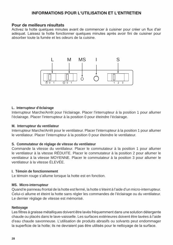
INFORMATIONS POUR L'UTILISATION ET L'ENTRETIEN
Pour de meilleurs résultats
absorber toute la fumée et les odeurs de la cuisine.
L. Interrupteur d’éclairageInterrupteur Marche/Arrêt pour l'éclairage. Placer l’interrupteur à la position 1 pour allumer l’éclairage. Placer l’interrupteur à la position 0 pour éteindre l’éclairage.
M. Interrupteur du ventilateurInterrupteur Marche/Arrêt pour le ventilateur. Placer l’interrupteur à la position 1 pour allumer le ventilateur. Placer l’interrupteur à la position 0 pour éteindre le ventilateur.
S. Commutateur de réglage de vitesse du ventilateurCommande la vitesse du ventilateur. Placer le commutateur à la position 1 pour allumer le ventilateur à la vitesse RÉDUITE. Placer le commutateur à la position 2 pour allumer le ventilateur à la vitesse MOYENNE. Placer le commutateur à la position 3 pour allumer le ventilateur à la vitesse ÉLEVÉE.
I. Témoin de fonctionnementLe témoin rouge s’allume lorsque la hotte est en fonction.
MS. Micro-interrupteurQuand le panneau frontal de la hotte est fermé, la hotte s’éteint à l’aide d’un micro-interrupteur. Celui-ci allume et éteint la hotte sans régler les commandes de l’éclairage ou du ventilateur. Le dernier réglage de vitesse est mémorisé.
Nettoyage
chaude ou placés dans le lave-vaisselle. Les surfaces extérieures doivent être lavées à l’aide d’eau chaude savonneuse. L’utilisation de produits abrasifs ou solvants peut endommager
L M MS I S

29
solution d'eau chaude savonneuse ou dans le lave-vais-selle. Ils devraient être nettoyés tous les 2 mois, ou plus fréquemment en cas d'utilisation particulièrement intensive. •
l'arrière de l'appareil et en le tirant vers le bas.• -
ment avant de le réinstaller (un changement de la couleur
• Remettez-le en place, en vous assurant que la poignée se trouve vers l'avant.
• métallique.
peuvent être régénérés. Ils devraient être remplacés en-viron tous les 4 mois d'utilisation, ou plus souvent en cas d'utilisation intensive.•
sens des aiguilles d'une montre (vers l'arrière) jusqu'à ce qu'il se dégage du carter du moteur, puis en le tirant vers le côté.
• -lateur et poussez-les vers l'intérieur. Tournez ensuite le
(vers l'avant) jusqu'à ce qu'il soit bien installé.
de type GU10
• Coupez l'alimentation électrique avant de remplacer les ampoules et assurez-vous qu'elles sont froides au toucher avant de commencer.
• Dégagez délicatement l'écran protecteur de la lampe en faisant un effet de levier vers le bas à l'aide d'un tournevis à lame plate sous l'anneau métallique.
• Une fois dégagé l'écran protecteur de la lampe, retirez l'ampoule halogène de la base. Faites tourner légèrement vers la gauche et retirez-la du socle.
• Remplacez l'ampoule avec une nouvelle du même type, en vous assurant d'insérer correctement les deux connecteurs dans leur logement sur le socle.
• Remettez l'écran protecteur de la lampe en place. • Lorsque les connecteurs de l'ampoule sont en place,
faites tourner légèrement vers la droite pour verrouiller.

30
Schéma de câblage

31
4 janvier 2016
GARANTIE LIMITÉE ET SERVICE FABER
Tous les produits Faber font l'objet d'une garantie contre les défauts de matériel et de main-d'œuvre,accordée à l'acheteur original pour une période d'un (1) an à compter de la date d'achat initiale (preuve d'achat requise). Cette garantie couvre les frais de main-d'œuvre et les pièces de rechange. À sa discrétion, Faber peut réparer ou remplacer le produit ou les composants nécessaires à remettre le produit en bon état de marche. Pour bénéficier de services prévus par la garantie, veuillez communiquer avec le détaillant auprès duquel vous avez acheté la hotte de cuisine, ou encore avec le distributeur Faber de votre région. Si vous n'êtes pas en mesure de localiser un distributeur Faber dans votre région, veuillez communiquer avec nous au 508-358-5353 pour connaître le nom d'un distributeur à proximité.
Les éléments suivants ne sont pas visés par la garantie Faber :
1. Les appels au service de réparation visant à corriger l'installation de la hotte de cuisine, à recevoir des instructions sur l'utilisation de la hotte de cuisine, le remplacement ou la réparation des fusibles du domicile ou la correction des câblages ou de la plomberie du domicile. 2. Les appels au service de réparation visant à réparer ou remplacer les ampoules électriques de hotte, les fusibles ou les filtres. Ces pièces consommables ne sont pas couvertes par la garantie. 3. Les réparations si votre hotte de cuisine est employée à des fins autres que celles prévues, soit l'utilisation résidentielle normale pour une famille. 4. Les dommages découlant d'un accident, d'une modification, de l'utilisation incorrecte ou abusive, d'un incendie, d'une inondation, d'un cas de force majeure, d'une installation inadéquate, d'une installation non conforme aux codes en matière d'électricité ou de plomberie ou à la documentation fournie par Faber, ou encore d'une utilisation du produit non approuvée par Faber. 5. Les frais de main-d'œuvre ou de remplacement des pièces pour les appareils utilisés à l'extérieur des États-Unis ou du Canada, y compris toutes les hottes de cuisine Faber non-UL ou C-UL homologuées. 6. Les réparations à la hotte découlant de modifications non autorisées apportées à la hotte de cuisine. 7. Les frais encourus pour les déplacements et le transport de produits en région éloignée et les frais de cueillette et livraison. La réparation des hottes de cuisine Faber doit être réalisée à domicile.
LA PRÉSENTE GARANTIE NE PRÉVOIT AUCUNE FORME DE DÉDOMMAGEMENT EN CAS DE DOMMAGES ACCESSOIRES OU CONSÉCUTIFS, Y COMPRIS, SANS TOUTEFOIS S'Y LIMITER, LES DOMMAGES DIRECTS, INDIRECTS, ACCESSOIRES, PARTICULIERS OU CONSÉCUTIFS, LES LÉSIONS CORPORELLES/MORTELLES OU LA PERTE DE PROFITS. LA GARANTIE OFFERTE PAR FABER EST LIMITÉE AUX CONDITIONS ÉNONCÉES CI-DESSUS ET À LA PÉRIODE DE GARANTIE INDIQUÉE DANS LES PRÉSENTES ET EST EXCLUSIVE. SAUF DISPOSITIONS EXPRESSES CONTRAIRES DANS LE PRÉSENT ACCORD, FABER DÉCLINE TOUTE CONDITION, REPRÉSENTATION OU GARANTIE EXPLICITE OU IMPLICITE, Y COMPRIS, SANS TOUTEFOIS S'Y LIMITER, TOUTE GARANTIE IMPLICITE DE QUALITÉ MARCHANDE OU D'ADAPTATION À UN USAGE PARTICULIER.
Les droits qui vous sont conférés en vertu de la présente garantie peuvent varier d'une province ou d'un État
à l'autre.
No de modèle : ______________________________ No de série : _____________________________

991.0492.032_01 - 170123D003397_00