INSTALLATION INSTRUCTIONS - cromptonusa.comcromptonusa.com/IW256TD TF_ISSUE5.pdf · Page 1 of 2...
13
Paladin Transducers Class 0.5 Series 250 Power Factor Transducers Page 1 of 2 Ref: IW256TD/TF – Rev 5 – Sept 02 INSTALLATION INSTRUCTIONS Products Covered 256-TFT 256-TDS 256-TDT 256-TDB 256-TDA 256-TDE Introduction The power factor transducer measures phase between current and voltage and gives an output proportional to the power factor. Zero and span adjustments are accessible without opening the unit. The cases are moulded in a tough flame-retardant thermoplastic material. Installation Units should be installed in a dry position, not in direct sunlight and where the ambient temperature is reasonably stable and not outside the range 0 to 60ºC. Mounting will normally be on a vertical surface but other positions will not affect operation. Vibration should be kept to a minimum, 256 units are designed for mounting on a 35mm rail to DIN 46277. Alternatively they may be screw fixed. To mount on a DIN rail, the top edge of the cutout on the back is hooked over one edge of the rail and bottom edge carrying the release clips clicked into place. Check that the unit is firmly fixed. Removal or repositioning may be achieved by levering down the release clip and lifting the unit up and off the rail. Connection diagrams should be carefully followed to ensure correct polarity and phase rotation. External current and voltage transformers may be used to extend the range. Connection wires should be sized to comply with applicable regulations and codes of practice. These products do not have internal fuses therefore external fuses must be used for safety protection under fault conditions. Earth/Ground Connections For safety reasons, CT secondary connections should be grounded according to local codes of practice. Electromagnetic Compatibility This unit has been designed to provide protection against EM (electro-magnetic) interference in line with requirements of EU and other regulations. Precautions necessary to provide proper operation of this and adjacent equipment will be installation dependent and so the following can only be general guidance:- • Avoid routing wiring to this unit alongside cables and products that are, or could be, a source of interference. • The auxiliary supply to the unit should not be subject to excessive interference. In some cases, a supply line filter may be required. • To protect the product against incorrect operation or permanent damage, surge transients must be controlled. It is good EMC practice to suppress differential surges to 2kV or less at the source. The unit has been designed to automatically recover from typical transients, however in extreme circumstances it may be necessary to temporarily disconnect the auxiliary supply for a period of greater than 5 seconds to restore correct operation. • Screened communication and small signal leads are recommended and may be required. These and other connecting leads may require the fitting of RF suppression components, such as ferrite absorbers, line filters etc., if RF fields cause problems. It is good practice to install sensitive electronic instruments that are performing critical functions in EMC enclosures that protect against electrical interference causing a disturbance in function. Side labels show full connection information and data, including Type No., Range, Voltage, Current, Frequencies, Auxiliary Supply (when required), Class Index and Output. Setting Up The units are adjusted before despatch but, should it be necessary to trim the transducer output to suit system inaccuracy, this may be carried out by adjusting the potentiometers located under the bungs on the front panel. It should be noted that this might affect the accuracy of the product, resulting in the need for re-calibration. Typical Applications For measuring power factor between current and voltage to ensure power factor correction is optimised. For large variations use the auxiliary powered version. Self-powered units permit voltage variations upto ± 20%. Operation This model measures the timing difference between the voltage and current waveforms and the internal microcontroller calculates the corresponding power factor. This method ensures a linear output suitable for directly driving a digital meter or other linear indicator, e.g. chart recorder, computer, plc. Maintenance No routine maintenance is required. Should repair be necessary, it is recommended that the transducer be returned to the factory or to the nearest Crompton Instrument Service Centre. LOW VOLTAGE DIRECTIVE:- This product complies with BSEN61010-1 Warning • During normal operation, voltages hazardous to life may be present at some of the terminals of this unit. Installation and servicing should be performed only by qualified, properly trained personnel' abiding by local regulations. Ensure all supplies are de-energised before attempting connection or other procedures. • It is recommended adjustments be made with the supplies de-energised, but if this is not possible, then extreme caution should be exercised. • Terminals should not be user accessible after installation and external installation provisions must be sufficient to prevent hazards under fault conditions. Fusing and connections This unit must be fitted with external fuses in voltage and auxiliary supply lines. Voltage input lines must be fused with a quick blow fuse 1A maximum. Auxiliary supply lines must be fused with a slow blow fuse rated 1A maximum. Choose fuses of a type and with a breaking capacity appropriate to the supply and in accordance with local regulations. Screw torque Main terminal screws should be tightened to 1.35Nm or 1.0 ft/lbf only. Detachable terminal connector screws should be tightened to 0.9Nm or 0.7 ft/lbf only. Where fitted, terminal covers are held in place by miniature self tapping screws into plastic. These screws should be tightened by hand only, sufficiently to secure the terminal cover and prevent it vibrating.
Transcript of INSTALLATION INSTRUCTIONS - cromptonusa.comcromptonusa.com/IW256TD TF_ISSUE5.pdf · Page 1 of 2...
Paladin TransducersClass 0.5 Series 250Power Factor Transducers
Page 1 of 2
Ref: IW256TD/TF – Rev 5 – Sept 02
INSTALLATION INSTRUCTIONS
Products Covered256-TFT 256-TDS256-TDT 256-TDB256-TDA 256-TDE
IntroductionThe power factor transducer measures phase between currentand voltage and gives an output proportional to the power factor.Zero and span adjustments are accessible without opening theunit.The cases are moulded in a tough flame-retardant thermoplasticmaterial.
InstallationUnits should be installed in a dry position, not in direct sunlightand where the ambient temperature is reasonably stable and notoutside the range 0 to 60ºC. Mounting will normally be on avertical surface but other positions will not affect operation.Vibration should be kept to a minimum, 256 units are designedfor mounting on a 35mm rail to DIN 46277. Alternatively theymay be screw fixed.
To mount on a DIN rail, the top edge of the cutout on the back ishooked over one edge of the rail and bottom edge carrying therelease clips clicked into place. Check that the unit is firmly fixed.Removal or repositioning may be achieved by levering down therelease clip and lifting the unit up and off the rail.
Connection diagrams should be carefully followed to ensurecorrect polarity and phase rotation. External current and voltagetransformers may be used to extend the range. Connection wiresshould be sized to comply with applicable regulations and codesof practice. These products do not have internal fuses thereforeexternal fuses must be used for safety protection under faultconditions.
Earth/Ground ConnectionsFor safety reasons, CT secondary connections should begrounded according to local codes of practice.
Electromagnetic CompatibilityThis unit has been designed to provide protection against EM(electro-magnetic) interference in line with requirements of EUand other regulations. Precautions necessary to provide properoperation of this and adjacent equipment will be installationdependent and so the following can only be general guidance:-• Avoid routing wiring to this unit alongside cables and
products that are, or could be, a source of interference.• The auxiliary supply to the unit should not be subject to
excessive interference. In some cases, a supply line filtermay be required.
• To protect the product against incorrect operation orpermanent damage, surge transients must be controlled. Itis good EMC practice to suppress differential surges to 2kVor less at the source. The unit has been designed toautomatically recover from typical transients, however inextreme circumstances it may be necessary to temporarilydisconnect the auxiliary supply for a period of greater than 5seconds to restore correct operation.
• Screened communication and small signal leads arerecommended and may be required. These and otherconnecting leads may require the fitting of RF suppressioncomponents, such as ferrite absorbers, line filters etc., if RFfields cause problems.
It is good practice to install sensitive electronic instruments thatare performing critical functions in EMC enclosures that protectagainst electrical interference causing a disturbance in function.
Side labels show full connection information and data, includingType No., Range, Voltage, Current, Frequencies, AuxiliarySupply (when required), Class Index and Output.
Setting UpThe units are adjusted before despatch but, should it benecessary to trim the transducer output to suit systeminaccuracy, this may be carried out by adjusting thepotentiometers located under the bungs on the front panel. Itshould be noted that this might affect the accuracy of the product,resulting in the need for re-calibration.
Typical ApplicationsFor measuring power factor between current and voltage toensure power factor correction is optimised. For large variationsuse the auxiliary powered version. Self-powered units permitvoltage variations upto ± 20%.
OperationThis model measures the timing difference between the voltageand current waveforms and the internal microcontroller calculatesthe corresponding power factor. This method ensures a linearoutput suitable for directly driving a digital meter or other linearindicator, e.g. chart recorder, computer, plc.
MaintenanceNo routine maintenance is required. Should repair be necessary,it is recommended that the transducer be returned to the factoryor to the nearest Crompton Instrument Service Centre.
LOW VOLTAGE DIRECTIVE:- This product complies withBSEN61010-1
Warning• During normal operation, voltages hazardous to life may be
present at some of the terminals of this unit. Installation andservicing should be performed only by qualified, properlytrained personnel' abiding by local regulations. Ensure allsupplies are de-energised before attempting connection orother procedures.
• It is recommended adjustments be made with the suppliesde-energised, but if this is not possible, then extremecaution should be exercised.
• Terminals should not be user accessible after installationand external installation provisions must be sufficient toprevent hazards under fault conditions.
Fusing and connectionsThis unit must be fitted with external fuses in voltage andauxiliary supply lines. Voltage input lines must be fused with aquick blow fuse 1A maximum. Auxiliary supply lines must befused with a slow blow fuse rated 1A maximum. Choose fuses ofa type and with a breaking capacity appropriate to the supply andin accordance with local regulations.
Screw torqueMain terminal screws should be tightened to 1.35Nm or 1.0 ft/lbfonly. Detachable terminal connector screws should be tightenedto 0.9Nm or 0.7 ft/lbf only. Where fitted, terminal covers are heldin place by miniature self tapping screws into plastic. Thesescrews should be tightened by hand only, sufficiently to securethe terminal cover and prevent it vibrating.
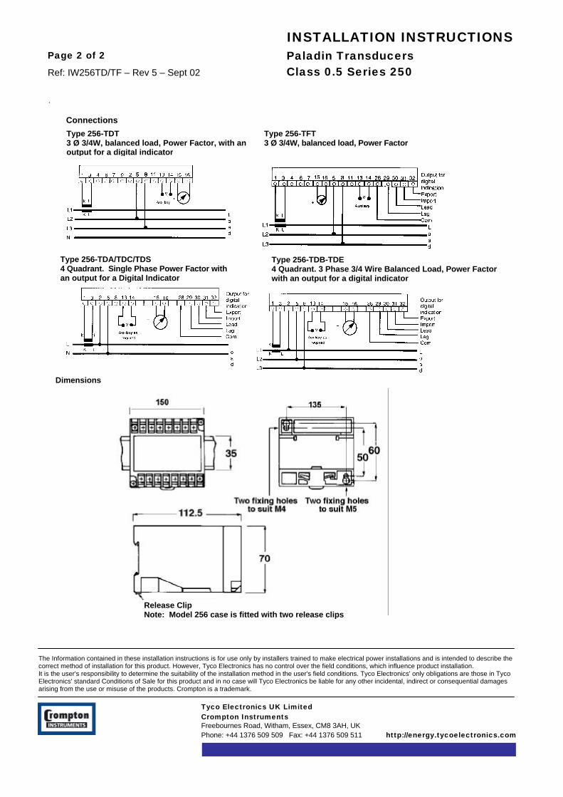
Paladin TransducersClass 0.5 Series 250
Page 2 of 2
Ref: IW256TD/TF – Rev 5 – Sept 02
INSTALLATION INSTRUCTIONS
Tyco Electronics UK LimitedCrompton InstrumentsFreebournes Road, Witham, Essex, CM8 3AH, UKPhone: +44 1376 509 509 Fax: +44 1376 509 511 http://energy.tycoelectronics.com
The Information contained in these installation instructions is for use only by installers trained to make electrical power installations and is intended to describe thecorrect method of installation for this product. However, Tyco Electronics has no control over the field conditions, which influence product installation.It is the user's responsibility to determine the suitability of the installation method in the user's field conditions. Tyco Electronics' only obligations are those in TycoElectronics' standard Conditions of Sale for this product and in no case will Tyco Electronics be liable for any other incidental, indirect or consequential damagesarising from the use or misuse of the products. Crompton is a trademark.
.
Release ClipNote: Model 256 case is fitted with two release clips
Dimensions
15 16
Type 256-TDA/TDC/TDS4 Quadrant. Single Phase Power Factor withan output for a Digital Indicator
Type 256-TDB-TDE4 Quadrant. 3 Phase 3/4 Wire Balanced Load, Power Factorwith an output for a digital indicator
Type 256-TDT3 Ø 3/4W, balanced load, Power Factor, with anoutput for a digital indicator
Type 256-TFT3 Ø 3/4W, balanced load, Power Factor
Connections

Paladin TransducersClass 0.5 Series 250Phase Angle
Page 1 of 2
Ref: IW256TPB/B/S/T – Rev 7 – Sept 02
INSTALLATION INSTRUCTIONS
Products Covered256-TPA - Phase Angle Single Phase 180º - 0 - 180º256-TPB - Phase Angle 3 Phase 180º - 0 - 180º256-TPT - Phase Angle 3 Phase 0.5 - 1 - 0.5
or 0.2 - 1 - 0.8256-TPS - Phase Angle Single Phase 0.5 - 1 - 0.5 or 0.2 - 1 - 0.8
IntroductionThe phase angle transducer measures the phase anglebetween current and voltage and gives an outputproportional to the phase angle. Zero and span adjustmentsare accessible without opening the unit.The cases may be DIN rail mounted or screw fixed.
InstallationUnits should be installed in a dry position, not in directsunlight and where the ambient temperature is reasonablystable and not outside the range 0 to 60ºC. Mounting willnormally be on a vertical surface but other positions will notaffect operation. Vibration should be kept to a minimum,These units are designed for mounting on a 35mm rail toDIN 46277. Alternatively, they may be screw fixed.
To mount on a DIN rail, the top edge of the cutout on theback is hooked over one edge of the rail and bottom edgecarrying the release clips clicked into place. Check that theunit is firmly fixed. Removal or repositioning may beachieved by levering down the release clip and lifting theunit up and off the rail.Connection diagrams should be carefully followed to ensurecorrect polarity and phase rotation. External current andvoltage transformers may be used to extend the range.Connection wires should be sized to comply with applicableregulations and codes of practice. These products do nothave internal fuses therefore external fuses must be usedfor safety protection under fault conditions.
Fusing and connections• This unit must be fitted with external fuses in voltage
and auxiliary supply lines.• Voltage input lines must be fused with a quick blow
fuse 1A maximum.• Auxiliary supply lines must be fused with a slow blow
fuse rated 1A maximum.• Choose fuses of a type and with a breaking capacity
appropriate to the supply and in accordance with localregulations.
Screw torqueMain terminal screws should be tightened to 1.35Nm or 1.0ft/lbf only. Detachable terminal connector screws should betightened to 0.9Nm or 0.7 ft/lbf only. Where fitted, terminalcovers are held in place by miniature self tapping screwsinto plastic. These screws should be tightened by handonly, sufficiently to secure the terminal cover and prevent itvibrating.
Electromagnetic CompatibilityThis unit has been designed to provide protection againstEM (electro-magnetic) interference in line with requirementsof EU and other regulations. Precautions necessary toprovide proper operation of this and adjacent equipment will
be installation dependent and so the following can only begeneral guidance:-• Avoid routing wiring to this unit alongside cables and
products that are, or could be, a source of interference.• The auxiliary supply to the unit should not be subject to
excessive interference. In some cases, a supply linefilter may be required.
• To protect the product against incorrect operation orpermanent damage, surge transients must becontrolled. It is good EMC practice to suppressdifferential surges to 2kV or less at the source. Theunit has been designed to automatically recover fromtypical transients, however in extreme circumstances itmay be necessary to temporarily disconnect theauxiliary supply for a period of greater than 5 secondsto restore correct operation.
• Screened communication and small signal leads arerecommended and may be required. These and otherconnecting leads may require the fitting of RFsuppression components, such as ferrite absorbers,line filters etc., if RF fields cause problems.
• It is good practice to install sensitive electronicinstruments that are performing critical functions inEMC enclosures that protect against electricalinterference causing a disturbance in function.
For assistance on protection requirements please contactyour local sales office.
CommissioningThe units are calibrated at the factory for full accuracy. Nofurther adjustments are required. Zero and span adjustmentwhere provided are under the bungs on the front panel.Trimming these will degrade the accuracy of this transducer,but may be used to compensate for local conditions.
Typical ApplicationsFor measuring phase angle between current and voltage toensure power factor correction is optimised. For largevariations use the auxiliary powered version. Self-poweredunits permit voltage variations upto ±20%.
OperationFor use on most single phase balanced systems, this unitmeasures phase angle and provides milliamp outputproportional to angle. Current and voltage inputs are fed toseparate zero crossing detectors and resultant pulses arefed to bistable comparator. The output from this is filteredand then amplified to give a dc output directly proportional tothe phase angle.
Low Voltage Directive:- This product complies withBSEN61010-1.
Warning• During normal operation, voltages hazardous to life
may be present at some of the terminals of this unit.Installation and servicing should be performed onlyby qualified, properly trained personnel' abiding bylocal regulations. Ensure all supplies are de-energised before attempting connection or otherprocedures.

Tyco Electronics UK LimitedCrompton InstrumentsFreebournes Road, Witham, Essex, CM8 3AH, UKPhone: +44 1376 509 509 Fax: +44 1376 509 511 http://energy.tycoelectronics.com
The Information contained in these installation instructions is for use only by installers trained to make electrical power installations and is intended to describe thecorrect method of installation for this product. However, Tyco Electronics has no control over the field conditions, which influence product installation.It is the user's responsibility to determine the suitability of the installation method in the user's field conditions. Tyco Electronics' only obligations are those in TycoElectronics' standard Conditions of Sale for this product and in no case will Tyco Electronics be liable for any other incidental, indirect or consequential damagesarising from the use or misuse of the products. Crompton is a trademark.
Paladin TransducersClass 0.5 Series 250Phase Angle
Page 2 of 2
Ref: IW256TPB/B/S/T – Rev 7 – Sept 02
INSTALLATION INSTRUCTIONS
• It is recommended adjustments be made with thesupplies de-energised, but if this is not possible,then extreme caution should be exercised.
• Terminals should not be user accessible afterinstallation and external installation provisions mustbe sufficient to prevent hazards under faultconditions.
MaintenanceNo routine maintenance is required. Should repair benecessary it is recommended that the transducer bereturned to the factory or to the nearest CromptonInstrument Service Centre.
Conversion to P.F.The transducer output, if displayed on an analog meter,produces an inconvenient non-linear scale. Computerusers may find the need for a linearising program. Othertransducers are available from Crompton Instrumentswith a linearised output if required.
15 16
15 16
Connection diagrams
256TPA/TPSPhase angle single phase
256TPBPhase angle 3 phase
256TPTPhase Angle 3 Phase

Paladin TransducersClass 0.5 250 SeriesVoltage and Current 3 in 1
Page 1 of 2
Ref: IW250T – Revision 6 – Sept 02
INSTALLATION INSTRUCTIONS
Models Covered256-TAL 256-TVL256-TAR 256-TVR256-TAS 256-TVS
IntroductionPaladin Transducers give a dc output proportional tothe input. Zero and span adjustments are accessiblewithout opening the transducer.
Warning• During normal operation, voltages hazardous to life
may be present at some of the terminals of thisunit. Installation and servicing should beperformed only by qualified, properly trainedpersonnel' abiding by local regulations. Ensure allsupplies are de-energised before attemptingconnection or other procedures.
• It is recommended adjustments be made with thesupplies de-energised, but if this is not possible,then extreme caution should be exercised.
• Terminals should not be user accessible afterinstallation and external installation provisions mustbe sufficient to prevent hazards under faultconditions.
InstallationThe Transducer should be installed in a dry position,not in direct sunlight and where the ambienttemperature is reasonably stable and will not be outsidethe range 0 to 60 degrees Celsius. Mounting willnormally be on a vertical surface but other positions willnot affect the operation. Vibration should be kept to aminimum. The Transducers are designed for mountingon a 35mm rail to DIN 46277. Alternatively they maybe screw fixed to mount a Transducer on a DIN rail; thetop edge of the cutout on the back is hooked over oneedge of the rail and bottom edge carrying the releaseclip clicked into place. Check that the unit is firmlyfixed. Removal or repositioning may be achieved bylevering down the release clip and lifting the unit up andoff the rail.Connection diagrams should be carefully followed toensure correct polarity and phase rotation whereapplicable. External current or voltage transformersmay be used to extend the range. Connection wiresshould be sized to comply with applicable regulationsand codes of practice. These products do not haveinternal fuses therefore external fuses must be used forsafety protection under fault conditions.Side labels show full connection information and data.
Electromagnetic CompatibilityThis unit has been designed to provide protectionagainst EM (electro-magnetic) interference in line withrequirements of EU and other regulations. Precautionsnecessary to provide proper operation of this andadjjacent equipment will be installation dependent andso the following can only be general guidance:-• Avoid routing wiring to this unit alongside cables
and products that are, or could be, a source ofinterference.
• The auxiliary supply to the unit should not besubject to excessive interference. In some cases,a supply line filter may be required.
• To protect the product against incorrect operationor permanent damage, surge transients must becontrolled. It is good EMC practice to suppressdifferential surges to 2kV or less at the source.The unit has been designed to automaticallyrecover from typical transients, however in extremecircumstances it may be necessary to temporarilydisconnect the auxiliary supply for a period ofgreater than 5 seconds to restore correctoperation.
• Screened communication and small signal leadsare recommended and may be required. Theseand other connecting leads may require the fittingof RF suppression components, such as ferriteabsorbers, line filters etc., if RF fields causeproblems.
• It is good practice to install sensitive electronicinstruments that are performing critical functions inEMC enclosures that protect against electricalinterference causing a disturbance in function.
Fusing and connections• This unit must be fitted with external fuses in voltage
and auxiliary supply lines.• Voltage input lines must be fused with a quick blow
fuse 1A maximum.• Auxiliary supply lines must be fused with a slow
blow fuse rated 1A maximum.• Choose fuses of a type and with a breaking capacity
appropriate to the supply and in accordance withlocal regulations.
Screw torqueMain terminal screws should be tightened to 1.35Nm or1.0 ft/lbf only. Detachable terminal connector screwsshould be tightened to 0.9Nm or 0.7 ft/lbf only. Wherefitted, terminal covers are held in place by miniature selftapping screws into plastic. These screws should betightened by hand only, sufficiently to secure theterminal cover and prevent it vibrating.
CommissioningThe units are calibrated at the factory for full accuracy.No further adjustments are required. Zero and spanadjustment where provided are under the bungs on thefront panel. Trimming these will degrade the accuracyof this transducer, but may be used to compensate forlocal condiitions.

Tyco Electronics UK LimitedCrompton InstrumentsFreebournes Road, Witham, Essex, CM8 3AH, UKPhone: +44 1376 509 509 Fax: +44 1376 509 511 http://energy.tycoelectronics.com
The Information contained in these installation instructions is for use only by installers trained to make electrical power installations and is intended to describe thecorrect method of installation for this product. However, Tyco Electronics has no control over the field conditions, which influence product installation.It is the user's responsibility to determine the suitability of the installation method in the user's field conditions. Tyco Electronics' only obligations are those in TycoElectronics' standard Conditions of Sale for this product and in no case will Tyco Electronics be liable for any other incidental, indirect or consequential damagesarising from the use or misuse of the products. Crompton is a trademark.
Paladin TransducersClass 0.5 250 SeriesVoltage and Current
Page 2 of 2
Ref: IW250T – Revision 6 – Sept 02
INSTALLATION INSTRUCTIONS
Type 256-TVL, TVR, TVS3 ø 3 W Voltage, 3 Outputs
Type 256-TAL, TAR, TAS3 ø Current, 3 Outputs
Typical ApplicationsSwitchboards, distribution panels, control panels, SCADAsystems, local and remote monitoring. The product housing isindustry standard.
MaintenanceNo routine maintenance is required. Should repair benecessary it is recommended that the transducer be returnedto the factory or to the nearest Crompton Instruments ServiceCentre.

Paladin TransducersClass 0.5 Series 250Linear IntegratorPulsed Output Transducer
Page 1 of 2
Ref: IW253TIK – Rev 5 –Sept 02
INSTALLATION INSTRUCTIONS
Product Covered253-TIK
IntroductionThe Transducer Indicator derives its input from a d.c. milliampsignal that might be typically produced by a Watt transducer,such as the Crompton “Paladin” 256-TW.Output of input current versus time is given by the number ofcontact closures of the in-built relay which may be varied over a10,000 to 100/hr range to suit the application. This is normallyset in the factory.
InstallationUnits should be installed in a dry position, not in direct sunlightand where the ambient temperature is reasonably stable and willnot be outside the range 0 - 60°C during operation. Mountingwill normally be on a vertical surface but other positions will notaffect operation. Vibration should be kept to a minimum. 253units are designed for mounting on DIN rail. They may also bescrew fixed using an adaptor. To mount on a Din rail, to topedge of the cutout on the back is hooked over one edge of therail and the bottom edge carrying the release clip clicked in toplace. Check that the unit is firmly fixed. Removal orrepositioning may be achieved by levering down the release clipand lifting the unit up and off the rail. Connection wires shouldbe sized to comply with application regulations or code ofpractice.
The products do not have internal fuses therefore external fusesmust be used for safety protection under fault conditions.
Electromagnetic CompatibilityThis unit has been designed to provide protection against EM(electro-magnetic) interference in line with requirements ofEU and other regulations. Precautions necessary to provideproper operation of this and adjacent equipment will beinstallation dependent and so the following can only begeneral guidance:-• Avoid routing wiring to this unit alongside cables and
products that are, or could be, a source of interference.• The auxiliary supply to the unit should not be subject to
excessive interference. In some cases, a supply linefilter may be required.
• To protect the product against incorrect operation orpermanent damage, surge transients must be controlled.It is good EMC practice to suppress differential surges to2kV or less at the source. The unit has been designedto automatically recover from typical transients, howeverin extreme circumstances it may be necessary totemporarily disconnect the auxiliary supply for a periodof greater than 5 seconds to restore correct operation.
• Screened communication and small signal leads arerecommended and may be required. These and otherconnecting leads may require the fitting of RFsuppression components, such as ferrite absorbers, linefilters etc., if RF fields cause problems.
It is good practice to install sensitive electronic instrumentsthat are performing critical functions in EMC enclosures thatprotect against electrical interference causing a disturbancein function.
Typical ApplicationsThe unit will find application in conjunction with a watttransducer where it is required to monitor auxiliary powerbeing generated and fed in to the normal supply system toextend its capacity or in import/export systems betweensupply sources.
OperationThe signal input current is converted to a high frequencypulse train by a voltage to frequency converter IC. To reducethis high frequency to the required low frequency output pulserate, a binary counter is employed. The division ratio is setby a series of links. To provide the relay with a constantwidth drive pulse, a monostable multivibrator is used.
Setting UpUnits are adjusted before despatch and therefore noadjustments are normally required.
MaintenanceUnless a fault develops the unit requires little attention.During routine servicing and inspection of the associatedequipment, the device should be inspected to normalstandards for this class of equipment. For example, removeaccumulations of dust and check connections for tightnessand corrosion.In the event of a repair being necessary, it is recommendedthat the instrument is returned to the factory or to the nearestCrompton Instruments ServiceCentre. Should repair be attempted then replacementcomponents must be of the same type, rating and toleranceas those used in the original circuit. With anyenquiry please quote the full model number found on thenameplate. The unit must be recalibrated after repair.
Fusing and connectionsThis unit must be fitted with external fuses in voltage andauxiliary supply lines. Voltage input lines must be fused witha quick blow fuse 1A maximum. Auxiliary supply lines mustbe fused with a slow blow fuse rated 1A maximum. Choosefuses of a type and with a breaking capacity appropriate tothe supply and in accordance with local regulations.
Warning• During normal operation, voltages hazardous to life may
be present at some of the terminals of this unit.Installation and servicing should be performed only byqualified, properly trained personnel' abiding by localregulations. Ensure all supplies are de-energised beforeattempting connection or other procedures.
• It is recommended adjustments be made with thesupplies de-energised, but if this is not possible, thenextreme caution should be exercised.
• Terminals should not be user accessible after installationand external installation provisions must be sufficient toprevent hazards under fault conditions.
Screw torqueMain terminal screws should be tightened to 1.35Nm or 1.0ft/lbf only. Detachable terminal connector screws should betightened to 0.9Nm or 0.7 ft/lbf only. Where fitted, terminalcovers are held in place by miniature self tapping screws intoplastic. These screws should be tightened by hand only,sufficiently to secure the terminal cover and prevent itvibrating.

Tyco Electronics UK LimitedCrompton InstrumentsFreebournes Road, Witham, Essex, CM8 3AH, UKPhone: +44 1376 509 509 Fax: +44 1376 509 511 http://energy.tycoelectronics.com
The Information contained in these installation instructions is for use only by installers trained to make electrical power installations and is intended to describe thecorrect method of installation for this product. However, Tyco Electronics has no control over the field conditions, which influence product installation.It is the user's responsibility to determine the suitability of the installation method in the user's field conditions. Tyco Electronics' only obligations are those in TycoElectronics' standard Conditions of Sale for this product and in no case will Tyco Electronics be liable for any other incidental, indirect or consequential damagesarising from the use or misuse of the products. Crompton is a trademark.
Paladin TransducerClass 0.5 250 SeriesLinear Integrator Pulsed Output Transducer
Page 2 of 2
Ref: IW253TIK – Rev 5 – Sept 02
INSTALLATION INSTRUCTIONS
LOW VOLTAGE DIRECTIVE:- This productcomplies with BSEN61010-1
This product is manufactured by CromptonInstruments, Freebournes Road, Witham, Essex.England CM8 3AH. Telephone +44 (0) 1376509509, Fax: +44 (0) 1376 509511.
Connection Diagram
Release Clip
Dimensions

Paladin Transducers Class 0.5250 Series - Watt, VA, Var, Volts,Amps, Frequency, Integrating &D.C. Transducers
Page 1 of 3
Ref: IW256NA – Rev 4 – Sept 02
INSTALLATION INSTRUCTIONS
Products Covered256-TW*U, 256-TX*U, 256-TY*U253-TA*U, 253-TV*U, 253-TZU256-TT*U,* = Any letter or number
IntroductionPaladin Transducers give a dc output proportionalto the input. Zero and span adjustments areaccessible without opening the transducer.The cases are moulded in a tough flame retardantmaterial.
InstallationThe Transducer should be installed in a dry position, notin direct sunlight and where the ambient temperature isreasonably stable and will not be outside the range 0-60°C. Mounting will normally be on a vertical surfacebut other positions will not affect the operation andvibration should be kept to a minimum. TheTransducers are designed for mounting on a 35mm railto DIN 46277. Alternatively they may be screw fixed. Tomount a Transducer on a DIN rail, the top edge of thecut-out on the back is hooked over one edge of the railand the bottom edge carrying the release clip clickedinto place. Check that the unit is firmly fixed. Removalor repositioning may be achieved by levering down therelease clip and lifting the unit up and off the rail.Connection diagrams should be carefully followed toensure correct polarity and phase rotation. Externalcurrent and voltage transformers may be used to extendthe range. Current Transformers must be used withmodels 256-TWG, 256-TWH, 256-TWN. These productsdo not have internal fuses therefore; external fusesmust be used for safety protection under faultconditions. Side labels show full connection informationand data.
Fusing and connectionsThis unit must be fitted with external fuses in voltageand auxiliary supply lines. Voltage input lines must befused with a quick blow fuse 1A maximum. Auxiliarysupply lines must be fused with a slow blow fuse rated1A maximum. Choose fuses of a type and with abreaking capacity appropriate to the supply and inaccordance with local regulations.
Electromagnetic CompatibilityThis unit has been designed to provide protectionagainst EM (electro-magnetic) interference in line withrequirements of EU and other regulations. Precautionsnecessary to provide proper operation of this andadjacent equipment will be installation dependent andso the following can only be general guidance:-• Avoid routing wiring to this unit alongside cables
and products that are, or could be, a source ofinterference.
• The auxiliary supply to the unit should not besubject to excessive interference. In some cases, asupply line filter may be required.
• To protect the product against incorrect operation orpermanent damage, surge transients must be
controlled. It is good EMC practice to suppressdifferential surges to 2kV or less at the source. Theunit has been designed to automatically recover fromtypical transients, however in extreme circumstancesit may be necessary to temporarily disconnect theauxiliary supply for a period of greater than 5seconds to restore correct operation.
§ Screened communication and small signal leads arerecommended and may be required. These andother connecting leads may require the fitting of RFsuppression components, such as ferrite absorbers,line filters etc., if RF fields cause problems.
§ It is good practice to install sensitive electronicinstruments that are performing critical functions inEMC enclosures that protect against electricalinterference causing a disturbance in function.
CommissioningThe units are calibrated at the factory for full accuracy.No further adjustments are required. Zero and spanadjustment where provided are under the bungs on thefront panel. Trimming these will degrade the accuracyof this transducer, but may be used to compensate forlocal conditions.
MaintenanceNo routine maintenance is required. Should repair benecessary it is recommended that the transducer bereturned to the factory or to the nearest CromptonInstruments Service Centre.
Screw torqueMain terminal screws should be tightened to 1.35Nm or1.0 ft/lbf only. Detachable terminal connector screwsshould be tightened to 0.9Nm or 0.7 ft/lbf only. Wherefitted, terminal covers are held in place by miniature selftapping screws into plastic. These screws should betightened by hand only, sufficiently to secure theterminal cover and prevent it vibrating.
Low Voltage Directive:- This product complies withBSEN61010-1
Warning• During normal operation, voltages hazardous to life
may be present at some of the terminals of this unit.Installation and servicing should be performed onlyby qualified, properly trained personnel' abiding bylocal regulations. Ensure all supplies are de-energised before attempting connection or otherprocedures.
• It is recommended adjustments be made with thesupplies de-energised, but if this is not possible,then extreme caution should be exercised.
• Terminals should not be user accessible afterinstallation and external installation provisions mustbe sufficient to prevent hazards under faultconditions.

Tyco Electronics UK LimitedCrompton InstrumentsFreebournes Road, Witham, Essex, CM8 3AH, UKPhone: +44 1376 509 509 Fax: +44 1376 509 511 http://energy.tycoelectronics.com
The Information contained in these installation instructions is for use only by installers trained to make electrical power installations and is intended to describe thecorrect method of installation for this product. However, Tyco Electronics has no control over the field conditions, which influence product installation.It is the user's responsibility to determine the suitability of the installation method in the user's field conditions. Tyco Electronics' only obligations are those in TycoElectronics' standard Conditions of Sale for this product and in no case will Tyco Electronics be liable for any other incidental, indirect or consequential damagesarising from the use or misuse of the products. Crompton is a trademark.
Paladin TransducersClass 0.2 250 Series
Page 2 of 3
Ref: IW256NA – Rev 4 – Sept 02
INSTALLATION INSTRUCTIONS
This product is manufactured by Crompton Instruments,Freebournes Road, Witham, Essex. England CM8 3AH.Telephone +44 (0) 1376 509509, Fax: +44 (0) 1376509511.
WATTS256-TWKU Single Phase 2 wire - Fig 1256-TWKU Q8 FA Single Phase 3 wire - Fig 2256-TWMU 3 phase 3 wire unbal - Fig 4256 TWNU 3 phase 4 wire unbal - Fig 5VAVA256-TYKU Single Phase 2 wire - Fig 1256-TYMU 3 Phase 3 wire bal or unbal - Fig 4256 TYNU 3 phase 4 wire bal or unbal - Fig 5VARS256-TXKU Single Phase 2 wire - Fig 1256-TXKU Q8 FA Single Phase 3 wire - Fig 2256-TXMU 3 phase 4 wire unbal - Fig 3256 TXNU 3 phase 3 wire unbal - Fig 4AC AMPERES (Fig 6)253-TAAU Average sensing input milliamps output253-TALU Average sensing input 4/20 milliamps o/p243-TARU RMS sensing input any standard outputAC VOLTS (Fig 7)253-TVAU Average sensing input milliamps output253-TVLU Average sensing input 4/20 milliamps o/p253-TVRU RMS sensing input any standard output253-TVZU Suppressed zero and standard outputFREQUENCY (Fig 7)253-THZU FrequencyINTEGRATING AC AMPERES (Fig 8)253-TAPU Time delay 8 minutes253-TAMU Time delay 15 minute253-TANU Time delay 30 minutesDC INPUT/DC OUTPUT (Fig 9)256-TTAU DC Current input256-TTVU DC Voltage input256-TTMU DC mV input256-TTFU Thermocouple -Fe/Const256-TTNU Thermocouple - Ni Cr5/NiAi256-TTPU Thermocouple - Pt Rh/Pt
Fig No: 5WATTStypes 256-TWNUor VA 256-TYNU(2 phase, 4 wire -3 CTS 2 phase/neutral Pts)(2 1/2 element)
Fig No:1WATTStypes 256-TWKUor VARStype 256-TXKUor VAtype 256-TYKU(single phase, 2 wiresingle element
Fig No:2WATTStypes 256TWKUor VARStype 256-TXKUor VAtype 256-TYKU(single phase, 3 wire singleelement
Fig No:3WATTStypes 256-TWNU(3 phase, 4 wire3 CT's3WYE/WYE pts)(2 1/2 element)
Fig No:4WATTStypes 256-TWMUor VARStype 256-TXMUor VAtype 256-TYMU(3 phase, 3 wire balanceor unbalanced loads)(Double element)

Tyco Electronics UK LimitedCrompton InstrumentsFreebournes Road, Witham, Essex, CM8 3AH, UKPhone: +44 1376 509 509 Fax: +44 1376 509 511 http://energy.tycoelectronics.com
The Information contained in these installation instructions is for use only by installers trained to make electrical power installations and is intended to describe thecorrect method of installation for this product. However, Tyco Electronics has no control over the field conditions, which influence product installation.It is the user's responsibility to determine the suitability of the installation method in the user's field conditions. Tyco Electronics' only obligations are those in TycoElectronics' standard Conditions of Sale for this product and in no case will Tyco Electronics be liable for any other incidental, indirect or consequential damagesarising from the use or misuse of the products. Crompton is a trademark.
Paladin TransducersClass 0.2 250 Series
Page 3 of 3
Ref: IW256NA – Rev 4 – Sept 02
INSTALLATION INSTRUCTIONS
A B N° of release clips253 75 60 1256 150 135 2
1) When no terminal screws are fitted to terminals 13 and 14the transducer application /characteristics do not necessitatethe use of a separate auxiliary supply
2) Point(s) indicated to be grounded - if no other point(s) in theCT and/or PT secondary circuit(s) are grounded.
3) Three phase hook-ups necessitate phase sequence 1-2-3
Dimensions
Fig No:6AC AMPEREStypes253-TAAU253-TALU253-TARU
Fig No:7AC VOLTStypes253-TVAU253-TVLU253-TVRU253-TVZU
or Frequency253-THZU
Fig No:8INTEGRATINGAC AMPEREStypes253-TAPU253-TAMU253-TANU
Fig No:9INPUT/DC OUTPUTtypes 256-TTAU(DC CURRENT INPUT)256-TTVU (DC VOLT INPUT)256-TTMU (DC mV INPUT)256-TTFU (THERMOCOUPLE -FE/CONST)256-TTNU (THERMOCOUPLE -NiCir/NiAi)256-TTPU (Thermocouple -PtRh/Pt)
Connection Diagrams (continued)

Paladin TransducersClass 0.5 250 SeriesCurrent, Voltage, Frequency, Resistance& Integrating Demand
Page 1 of 2
Ref: IW250TX253 – Rev 6 – Sept 02
INSTALLATION INSTRUCTIONS
Products Covered253-TAA 253-TRR 253-TAL 253-TRT253-TAM 253-TVA 253-TAN 253-TVL253-TAP 253-TVR 253-THZ 253-TVZ253-TDN 253-TAR 253-TDM 253-TDP253-TRP
IntroductionPaladin Transducers give a dc output proportional to the input.Zero and span adjustments are accessible without opening thetransducer. The cases are moulded in a tough flame-retardantmaterial.
InstallationThe Transducer should be installed in a dry position, not indirect sunlight and where the ambient temperature isreasonably stable and will not be outside the range 0 to 60degrees Celsius. Mounting will normally be on a verticalsurface but other positions will not affect the operation andvibration should be kept to a minimum. The Transducers aredesigned for mounting on a 35mm rail to DIN 46277.Alternatively they may be screw fixed.
To mount a Transducer on a DIN rail, the top edge of the cut-out on the back is hooked over one edge of the rail and bottomedge carrying the release clip clicked into place. Check that theunit is firmly fixed. Removal or repositioning may be achievedby levering down the release clip and lifting the unit up and offthe rail.
Connection diagrams should be carefully followed to ensurecorrect polarity and phase rotation where applicable. Externalvoltage transformers may be used to extend the range.Connection wires should be sized to comply with applicableregulations and codes of practice. These products do not haveinternal fuses therefore external fuses must be used for safetyprotection under fault conditions.
Earth/Ground ConnectionsFor safety reasons, CT secondary connections should begrounded according to local codes of practice.Side labels show full connection information and data.
CommissioningThe units are calibrated at the factory for full accuracy. Nofurther adjustments are required. Zero and span adjustmentwhere provided are under the bungs on the front panel.Resetting these will degrade the accuracy of this transducer,but may be used to compensate for system errors etc. typically10% of the span of the control concerned.
Fusing and connections1. This unit must be fitted with external fuses in voltage and
auxiliary supply lines.2. Voltage input lines must be fused with a quick blow fuse
1A maximum.3. Auxiliary supply lines must be fused with a slow blow fuse
rated 1A maximum.4. Choose fuses of a type and with a breaking capacity
appropriate to the supply and in accordance with localregulations.
5. Where fitted, CT secondaries must be grounded inaccordance with local regulations.
Electromagnetic CompatibilityThis unit has been designed to provide protection against EM(electro-magnetic) interference in line with requirements of EUand other regulations. Precautions necessary to provide properoperation of this and adjacent equipment will be installationdependent and so the following can only be general guidance:-
• Avoid routing wiring to this unit alongside cables andproducts that are, or could be, a source of interference.
• The auxiliary supply to the unit should not be subject toexcessive interference. In some cases, a supply line filtermay be required.
• To protect the product against incorrect operation orpermanent damage, surge transients must be controlled. Itis good EMC practice to suppress differential surges to2kV or less at the source. The unit has been designed toautomatically recover from typical transients, however inextreme circumstances it may be necessary to temporarilydisconnect the auxiliary supply for a period of greater than5 seconds to restore correct operation.
• Screened communication and small signal leads arerecommended and may be required. These and otherconnecting leads may require the fitting of RF suppressioncomponents, such as ferrite absorbers, line filters etc., ifRF fields cause problems.It is good practice to install sensitive electronic instrumentsthat are performing critical functions in EMC enclosuresthat protect against electrical interference causing adisturbance in function.
For assistance on protection requirements please contact yourlocal sales office.
Low Voltage Directive:- This product complies with BS EN61010-1.
INSTALLATION INSTRUCTIONS
Dimensions
Warning• During normal operation, voltages hazardous to life may be
present at some of the terminals of this unit. Installation andservicing should be performed only by qualified, properly trainedpersonnel' abiding by local regulations. Ensure all supplies arede-energised before attempting connection or other procedures.
• It is recommended adjustments be made with the supplies de-energised, but if this is not possible, then extreme caution shouldbe exercised.
• Terminals should not be user accessible after installation andexternal installation provisions must be sufficient to preventhazards under fault conditions.
• This unit is not intended to function as part of a system providingthe sole means of fault protection - good engineering practicedictates that any critical function be protected by at least twoindependent and diverse means.
• Never open circuit the secondary winding of an energised currenttransformer.

Tyco Electronics UK LimitedCrompton InstrumentsFreebournes Road, Witham, Essex, CM8 3AH, UKPhone: +44 1376 509 509 Fax: +44 1376 509 511 http://energy.tycoelectronics.com
The Information contained in these installation instructions is for use only by installers trained to make electrical power installations and is intended to describe thecorrect method of installation for this product. However, Tyco Electronics has no control over the field conditions, which influence product installation.It is the user's responsibility to determine the suitability of the installation method in the user's field conditions. Tyco Electronics' only obligations are those in TycoElectronics' standard Conditions of Sale for this product and in no case will Tyco Electronics be liable for any other incidental, indirect or consequential damagesarising from the use or misuse of the products. Crompton is a trade mark.
Paladin TransducersClass 0.5 250 Series
Page 2 of 2
Ref: IW250TX253– Rev 6 – Sept 02
INSTALLATION INSTRUCTIONS
253-TALLive Zero Current253-TARRMS Current
253-TDP253-TDM253-TDNIntegrating DCCurrent
253-TVLLive Zero Voltage253-TVRRMS Voltage
253-TVZSuppressed ZeroVoltage253-THZFrequency
253-TRP/TRTTap Position &SlidewireTransmitter
253-TAACurrent AverageSensing
253-TAM253-TAN253-TAPIntegrating ACCurrent
253-TVAVoltage AverageSensing
256-TWS3 Phase 3 WireBalanced Load
253-TRRTemperatureTransmitter