INSTALLATION INSTRUCTIONS Split Mechanical Seal · 14 - Stuffing Box Gasket 15 ... 17 - Spring,...
16
442 ™ Split Mechanical Seal For Large Shaft Diameter Equipment - 12.25 in. to 18.00 in. (310 mm to 460 mm) MECHANICAL SEAL INSTALLATION INSTRUCTIONS 2 EQUIPMENT PREPARATION 1 3 4 ø 200 .005" 0,13 mm 32 μ" 0,8 μm R a .002" 0,05mm ≤ ≤ ø 1000 ≤ ≤ 125 μ" 3,2 μm ± ø R a ≤ ø ø CAUTIONS These instructions are general in nature. It is assumed that the installer is familiar with seals and certainly with the requirements of their plant for the successful use of mechanical seals. If in doubt, get assistance from someone in the plant who is familiar with seals or delay the installation until a seal representative is available. All necessary auxiliary arrangements for successful operation (heating, cooling, flushing) as well as safety devices must be employed. These decisions are to be made by the user. The chemical listing is intended as a general reference for this seal only. The decision to use this seal or any other Chesterton seal in a particular service is the customer's responsibility.
Transcript of INSTALLATION INSTRUCTIONS Split Mechanical Seal · 14 - Stuffing Box Gasket 15 ... 17 - Spring,...

442™ Split Mechanical SealFor Large Shaft Diameter Equipment - 12.25 in. to 18.00 in. (310 mm to 460 mm)
MECHANICAL SEALINSTALLATION INSTRUCTIONS
2
EQUIPMENT PREPARATION
1
3 4
ø200
.005"0,13 mm
32 µ"0,8 µm Ra
.002"0,05mm
≤
≤
ø1000
≤≤
125 µ"3,2 µm
±
øRa≤
øø
CAUTIONS
These instructions are general in nature. It is assumed that the installer is familiar with seals and certainly with the requirements of their plant for the successful use ofmechanical seals. If in doubt, get assistance from someonein the plant who is familiar with seals or delay the installationuntil a seal representative is available. All necessary auxiliary
arrangements for successful operation (heating, cooling,flushing) as well as safety devices must be employed. These decisions are to be made by the user. The chemicallisting is intended as a general reference for this seal only. The decision to use this seal or any other Chesterton seal in a particular service is the customer's responsibility.

2
Please read these instructions andmake sure you understand them beforeinstalling the seal.
Installation is easy provided the parts are handled and installed carefully. Before you remove the parts from thepackaging, prepare a clean work surfaceand make sure your hands are clean. Anycontaminants on the seal faces or splitsduring handling may cause seal failure.Prepare a clean work surface on which toplace parts during assembly/disassembly.
Prepare the Seal for Installation
The gland and holder come assembled;the split seal faces, O-rings, holder andgland gaskets, springs and bolt tabs arepackaged separately to protect againstdamage during shipping.
1. Disengage the socket head cap screwsfrom the gland halves. With the glandin a horizontal position, separate thehalves and place them on the cleanwork surface. Check to ensure thatthe socket head cap screw O-ringremains in place for installation ofseal on equipment.
2. Disengage the socket head cap screwsfrom the rotary holder halves andplace the holder halves on the worksurface. Check to ensure that the splitO-ring halves protrude equally(protrusion of 1/4” [6.3 mm] inopposing halves). See Seal RebuildR12 for details.
SEAL PREPARATION
3. Remove the rotary and stationary seal faces from their packages andplace on the clean work surface, facesides up.
4. Apply a thin film of grease to the glandgaskets and holder gaskets and seatthem in their respective grooves. Do not glue the gland or holdergaskets in place. (See Seal RebuildR8 and R17 for details).
5. Snap open the ball and socket joint of the O-rings by pulling at the seam.NOTE: The rotary O-ring has asmaller cross-section than thestationary O-ring.Do not apply grease or glue to theballs and sockets of the O-rings.
6. Install seal per Seal Installation.
NOTES:
The gland, rotary holder, and face halvesare matched pairs; mixing componentsfrom different seals will result in sealfailure.
Handle parts carefully. Remove greasyfingerprints from seal faces; check formisaligned face splits. These conditionsmay cause leakage.
Splits in all seal components should bestaggered; refer to Figure 2 throughoutinstallation for details.
EQUIPMENT START UP
1. Rotate the shaft by hand, if possible,to ensure no metal-to-metal contactwithin the seal. A slight drag may befound due to the seal face to facecontact but the shaft should rotate.
2. Attach appropriate environmentalcontrols to the seal. Take allnecessary precautions and follownormal safety procedures beforestarting the equipment.
3. Depending on how carefully the sealcomponents were handled duringinstallation, split seals may drip onstartup. For example, greasyfingerprints on the faces or misalignedface splits may cause leakage. Thistype of leakage usually decreasesand stops over a period of time as a face wears in or leak paths aresealed. However, leakage greaterthan 150 drops per minute should beinvestigated immediately. If leakageremains steady, check O-rings andgaskets for proper installation andcheck faces for chips, scratches andproper alignment.
Please Contact Chesterton MechanicalSeal Application Engineering forassistance regarding split seals.
TABLE 1 - SCREW TORQUE VALUES
Cup Point Set Screws 15 – 17 ft-lbf 20,3 – 23,0 Nm
Socket Head Cap Screws (W) 10 ft-lbf 13,5 Nm
Socket Head Cap Screws (X) 55 ft-lbf 74 Nm
Socket Head Cap Screws (Y) 50 ft-lbf 67,7 Nm
( W, X, Y ) – From Figure 1, Parts Identification Key

3
PARTS IDENTIFICATION
KEY1 - Rotary Holder Assembly2 - Socket Head Cap Screw (X)3 - Cup Point Set Screw4 - Holder Gasket5 - Shaft O-ring6 - Rotary O-ring7 - Rotary Face8 - Rotary Support Gasket9 - Stationary Face
10 - Stationary O-ring11 - Gland Gasket12 - Socket Head Cap Screw (Y)13 - Gland Bolt O-ring (Not shown)14 - Stuffing Box Gasket15 - Drive Lug16 - Spring17 - Spring, Auxiliary18 - Socket Head Cap Screw (W)
19 - Flat Washer20 - Centering Button21 - Gland Assembly22a - Bolt Tab22b - Bolt Tab Option23 - Stuffing Box Bolt24 - Installation Spacer
(Not shown – for installation only)
23
øG
øG
14 2 8 4 19
18
17
16
10
9
721611
5
3
1 15 12 13 20
23
22a
22b
FIGURE 1

SEAL INSTALLATION
4
1 2
4 5 6
Remove seal from packaging anddisassemble on clean work surface.See Seal Preparation for details.Install installation spacers on OD ofholder halves. Important: Installationspacer must contact the holder face.
Assemble rotary holder halves on toshaft and finger-tighten holder capscrews to keep holder in place. Note that holder gaskets are engagedin opposing grooves (see Seal Rebuild, R8).
Installation spacers should seat evenlyand firmly against stuffing box face andholder face.
Push on holder assembly to bottom outinstallation spacers to stuffing box face.Use hex wrench and alternately tightenholder cap screws (see Table 1).
Check gaps at holder splits; gapsshould be equal on both sides.
Alternately tighten 6 holder set screws(3 in each half) to shaft (see Table 1).
7 8 9a
Remove all installation spacers. Assemble rotary O-ring and stationaryO-ring around shaft. Note: Rotary O-ring has a thinner cross-section thanstationary O-ring. Caution: Do NotApply Grease to Ball and SocketJoints at any time.
Apply a thin film of grease to ends ofone stationary seal face half; assemblearound shaft. Slide seal face intostationary O-ring and apply a thin filmof grease to O-ring.
6X
6X
6X
3
B
A = B
A
10
2424
6
9

SEAL INSTALLATION
5
9b 9c 10
Apply a thin film of grease to ends of one rotary seal face half; assemblearound shaft. Slide seal face into rotary O-ring.
Apply a thin film of grease to rotary O-ring.
Align rotary face slots with drive lugs in rotary holder. Note: When properlyinstalled splits in seal face will be 90°apart from the holder splits; O-ringjoints should be 30°- 45° from holdersplits (see Figure 2).
90°
11 12 13
Press evenly on the back of thestationary seal face to engage drivelugs into rotary seal face slots.Important: Rotary support gasketsmust fit into the rotary face slots andcontact the sides of the drive lugs.When engaged correctly, the rotaryface surface at the splits should feelsmooth, without any step orroughness. Wipe face surfaces clean,removing all grease and fingerprintsfrom installation. After faces are clean,slide stationary face against rotaryface.
Assemble gland halves around sealcomponents on shaft; splits in thegland halves should be 90° from splitsin stationary seal face and 45° from the splits in the O-rings (see Figure 2).Note that the gland gaskets areengaged in opposing grooves. Finger-tighten gland socket head capscrews to hold gland halves in place(see Seal Rebuild, R17).
Align slots in stationary face withspring slots in gland.
4X7
6

SEAL INSTALLATION
6
14 16
Press gland halves together andalternately hand tighten gland capscrews for even compression. Ensure that the stuffing box facegasket is installed properly andremains flat at the splits. Use torquewrench to tighten gland cap screws(see Table 1).
Install gland bold tabs (see Figure 1)and stuffing box bolts; alternatelytighten to minimum bolt torque. Note:Stuffing box minimum bolt torque willbe dependent on application, bolt size,number of bolts and bolting pattern.Pictured: 4-bolt configuration withbolt tabs.
Install springs and tighten cap screws(see Table 1). Pictured: Standard 3-piece spring configuration.
6X
8X
15
17a 17b 17c
Standard 3-piece spring configuration. Optional 2-pc spring configuration(Application specific; ContactApplication Engineering forrecommendation).
Optional 1-pc. Spring configuration forDry Running Applications.
18
Installation Complete. See EquipmentStart Up.
22a

7
SEAL INSTALLATION
FIGURE 2Stagger all joints such that no split lines up
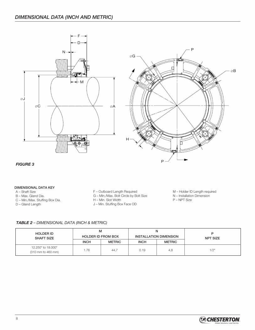
DIMENSIONAL DATA (INCH AND METRIC)
8
HOLDER IDM N
PSHAFT SIZE HOLDER ID FROM BOX INSTALLATION DIMENSION NPT SIZE
INCH METRIC INCH METRIC
12.250" to 18.000"1.76 44,7 0.19 4,8 1/2"
(310 mm to 460 mm)
øJ
øA
øG
øB
øC
F
D
P
H
P
N
M
FIGURE 3
DIMENSIONAL DATA KEYA – Shaft SizeB – Max. Gland Dia.C – Min./Max. Stuffing Box Dia.D – Gland Length
F – Outboard Length RequiredG – Min./Max. Bolt Circle by Bolt SizeH – Min. Slot WidthJ – Min. Stuffing Box Face OD
M – Holder ID Length requiredN – Installation DimensionP – NPT Size
TABLE 2 – DIMENSIONAL DATA (INCH & METRIC)

DIMENSIONAL DATA (INCH)
9
TABLE 3
A B
C
D F
G
H JSTANDARD TAB BOLT TAB OPTION
MIN MAX5/8” 3/4” 7/8” 5/8” 3/4” 7/8”
MIN MAX MIN MAX MIN MAX MIN MAX MIN MAX MIN MAX
12.250 23.05 13.71 14.71 4.48 4.50 16.87 20.04 17.00 19.91 17.12 19.79 19.83 24.08 19.96 23.96 20.08 23.83 0.85 15.83
12.500 23.44 14.10 15.10 4.48 4.50 17.27 20.43 17.39 20.31 17.52 20.18 20.23 24.48 20.35 24.35 20.48 24.23 0.85 16.23
12.750 23.84 14.50 15.50 4.48 4.50 17.66 20.83 17.79 20.70 17.91 20.58 20.62 24.87 20.75 24.74 20.87 24.62 0.85 16.62
13.000 23.84 14.50 15.50 4.48 4.50 17.66 20.83 17.79 20.70 17.91 20.58 20.62 24.87 20.75 24.74 20.87 24.62 0.85 16.62
13.250 24.23 14.89 15.89 4.48 4.50 18.05 21.22 18.18 21.10 18.30 20.97 21.01 25.26 21.14 25.14 21.26 25.01 0.85 17.02
13.500 24.62 15.28 16.28 4.48 4.50 18.45 21.61 18.57 21.49 18.70 21.36 21.41 25.66 21.53 25.53 21.66 25.41 0.85 17.41
13.750 24.62 15.28 16.28 4.48 4.50 18.45 21.61 18.57 21.49 18.70 21.36 21.41 25.66 21.53 25.53 21.66 25.41 0.85 17.41
14.000 25.02 15.68 16.68 4.48 4.50 18.84 22.01 18.97 21.88 19.09 21.76 21.80 26.05 21.93 25.93 22.05 25.80 0.85 17.80
14.250 25.41 16.07 17.07 4.48 4.50 19.24 22.40 19.36 22.28 19.49 22.15 22.20 26.44 22.32 26.32 22.45 26.19 0.85 18.20
14.500 25.41 16.07 17.07 4.48 4.50 19.24 22.40 19.36 22.28 19.49 22.15 22.20 26.44 22.32 26.32 22.45 26.19 0.85 18.20
14.750 25.81 16.47 17.47 4.48 4.50 19.63 22.80 19.75 22.67 19.88 22.55 22.59 26.84 22.71 26.71 22.84 26.59 0.85 18.59
15.000 25.81 16.47 17.47 4.48 4.50 19.63 22.80 19.75 22.67 19.88 22.55 22.59 26.84 22.71 26.71 22.84 26.59 0.85 18.59
15.250 26.20 16.86 17.86 4.48 4.50 20.02 23.19 20.15 23.06 20.27 22.94 22.98 27.23 23.11 27.11 23.23 26.98 0.85 18.98
15.500 26.59 17.25 18.25 4.48 4.50 20.42 23.58 20.54 23.46 20.67 23.33 23.38 27.63 23.50 27.50 23.63 27.38 0.85 19.38
15.750 26.59 17.25 18.25 4.48 4.50 20.42 23.58 20.54 23.46 20.67 23.33 23.38 27.63 23.50 27.50 23.63 27.38 0.85 19.38
16.000 26.99 17.65 18.65 4.48 4.50 20.81 23.98 20.94 23.85 21.06 23.73 23.77 28.02 23.90 27.89 24.02 27.77 0.85 19.77
16.250 27.38 18.04 19.04 4.48 4.50 21.20 24.37 21.33 24.25 21.45 24.12 24.16 28.41 24.29 28.29 24.41 28.16 0.85 20.17
16.500 27.38 18.04 19.04 4.48 4.50 21.20 24.37 21.33 24.25 21.45 24.12 24.16 28.41 24.29 28.29 24.41 28.16 0.85 20.17
16.750 27.77 18.43 19.43 4.48 4.50 21.60 24.76 21.72 24.64 21.85 24.51 24.56 28.81 24.68 28.68 24.81 28.56 0.85 20.56
17.000 27.77 18.43 19.43 4.48 4.50 21.60 24.76 21.72 24.64 21.85 24.51 24.56 28.81 24.68 28.68 24.81 28.56 0.85 20.56
17.250 28.17 18.83 19.83 4.48 4.50 21.99 25.16 22.12 25.03 22.24 24.91 24.95 29.20 25.08 29.07 25.20 28.95 0.85 20.95
17.500 28.56 19.22 20.22 4.48 4.50 22.39 25.55 22.51 25.43 22.64 25.30 25.35 29.59 25.47 29.47 25.60 29.34 0.85 21.35
17.750 28.56 19.22 20.22 4.48 4.50 22.39 25.55 22.51 25.43 22.64 25.30 25.35 29.59 25.47 29.47 25.60 29.34 0.85 21.35
18.000 28.96 19.62 20.62 4.48 4.50 22.78 25.95 22.90 25.82 23.03 25.70 25.74 29.99 25.86 29.86 25.99 29.74 0.85 21.74

10
DIMENSIONAL DATA (METRIC)
A B
C
D F
G
H JSTANDARD TAB BOLT TAB OPTION
MIN MAX12 mm 16 mm 20 mm 12 mm 16 mm 20 mm
MIN MAX MIN MAX MIN MAX MIN MAX MIN MAX MIN MAX
310 585,5 348,2 373,6 113,8 114,3 424,7 512,9 428,7 508,9 432,7 504,9 499,9 615,6 503,9 611,6 507,9 607,6 21,5 402,2
315 595,5 358,2 383,6 113,8 114,3 434,7 522,9 438,7 518,9 442,7 514,9 509,9 625,6 513,9 621,6 517,9 617,6 21,5 412,2
320 595,5 358,2 383,6 113,8 114,3 434,7 522,9 438,7 518,9 442,7 514,9 509,9 625,6 513,9 621,6 517,9 617,6 21,5 412,2
325 605,5 368,2 393,6 113,8 114,3 444,7 532,9 448,7 528,9 452,7 524,9 519,9 635,6 523,9 631,6 527,9 627,6 21,5 422,2
330 605,5 368,2 393,6 113,8 114,3 444,7 532,9 448,7 528,9 452,7 524,9 519,9 635,6 523,9 631,6 527,9 627,6 21,5 422,2
335 615,5 378,2 403,6 113,8 114,3 454,7 542,9 458,7 538,9 462,7 534,9 529,9 645,6 533,9 641,6 537,9 637,6 21,5 432,2
340 615,5 378,2 403,6 113,8 114,3 454,7 542,9 458,7 538,9 462,7 534,9 529,9 645,6 533,9 641,6 537,9 637,6 21,5 432,2
345 625,5 388,2 413,6 113,8 114,3 464,7 552,9 468,7 548,9 472,7 544,9 539,9 655,6 543,9 651,6 547,9 647,6 21,5 442,2
350 625,5 388,2 413,6 113,8 114,3 464,7 552,9 468,7 548,9 472,7 544,9 539,9 655,6 543,9 651,6 547,9 647,6 21,5 442,2
355 635,5 398,2 423,6 113,8 114,3 474,7 562,9 478,7 558,9 482,7 554,9 549,9 665,6 553,9 661,6 557,9 657,6 21,5 452,2
360 635,5 398,2 423,6 113,8 114,3 474,7 562,9 478,7 558,9 482,7 554,9 549,9 665,6 553,9 661,6 557,9 657,6 21,5 452,2
365 645,5 408,2 433,6 113,8 114,3 484,7 572,9 488,7 568,9 492,7 564,9 559,9 675,6 563,9 671,6 567,9 667,6 21,5 462,2
370 645,5 408,2 433,6 113,8 114,3 484,7 572,9 488,7 568,9 492,7 564,9 559,9 675,6 563,9 671,6 567,9 667,6 21,5 462,2
375 655,5 418,2 443,6 113,8 114,3 494,7 582,9 498,7 578,9 502,7 574,9 569,9 685,6 573,9 681,6 577,9 677,6 21,5 472,2
380 655,5 418,2 443,6 113,8 114,3 494,7 582,9 498,7 578,9 502,7 574,9 569,9 685,6 573,9 681,6 577,9 677,6 21,5 472,2
385 665,5 428,2 453,6 113,8 114,3 504,7 592,9 508,7 588,9 512,7 584,9 579,9 695,6 583,9 691,6 587,9 687,6 21,5 482,2
390 665,5 428,2 453,6 113,8 114,3 504,7 592,9 508,7 588,9 512,7 584,9 579,9 695,6 583,9 691,6 587,9 687,6 21,5 482,2
395 675,5 438,2 463,6 113,8 114,3 514,7 602,9 518,7 598,9 522,7 594,9 589,9 705,6 593,9 701,6 597,9 697,6 21,5 492,2
400 675,5 438,2 463,6 113,8 114,3 514,7 602,9 518,7 598,9 522,7 594,9 589,9 705,6 593,9 701,6 597,9 697,6 21,5 492,2
405 685,5 448,2 473,6 113,8 114,3 524,7 612,9 528,7 608,9 532,7 604,9 599,9 715,6 603,9 711,6 607,9 707,6 21,5 502,2
410 685,5 448,2 473,6 113,8 114,3 524,7 612,9 528,7 608,9 532,7 604,9 599,9 715,6 603,9 711,6 607,9 707,6 21,5 502,2
415 695,5 458,2 483,6 113,8 114,3 534,7 622,9 538,7 618,9 542,7 614,9 609,9 725,6 613,9 721,6 617,9 717,6 21,5 512,2
420 695,5 458,2 483,6 113,8 114,3 534,7 622,9 538,7 618,9 542,7 614,9 609,9 725,6 613,9 721,6 617,9 717,6 21,5 512,2
425 705,5 468,2 493,6 113,8 114,3 544,7 632,9 548,7 628,9 552,7 624,9 619,9 735,6 623,9 731,6 627,9 727,6 21,5 522,2
430 705,5 468,2 493,6 113,8 114,3 544,7 632,9 548,7 628,9 552,7 624,9 619,9 735,6 623,9 731,6 627,9 727,6 21,5 522,2
435 715,5 478,2 503,6 113,8 114,3 554,7 642,9 558,7 638,9 562,7 634,9 629,9 745,6 633,9 741,6 637,9 737,6 21,5 532,2
440 715,5 478,2 503,6 113,8 114,3 554,7 642,9 558,7 638,9 562,7 634,9 629,9 745,6 633,9 741,6 637,9 737,6 21,5 532,2
445 725,5 488,2 513,6 113,8 114,3 564,7 652,9 568,7 648,9 572,7 644,9 639,9 755,6 643,9 751,6 647,9 747,6 21,5 542,2
450 725,5 488,2 513,6 113,8 114,3 564,7 652,9 568,7 648,9 572,7 644,9 639,9 755,6 643,9 751,6 647,9 747,6 21,5 542,2
455 735,5 498,2 523,6 113,8 114,3 574,7 662,9 578,7 658,9 582,7 654,9 649,9 765,6 653,9 761,6 657,9 757,6 21,5 552,2
460 735,5 498,2 523,6 113,8 114,3 574,7 662,9 578,7 658,9 582,7 654,9 649,9 765,6 653,9 761,6 657,9 757,6 21,5 552,2
TABLE 4

1. Only the gland, rotary holder and springs are reused.Caution: The gland, holder and face halves are matched pairs; do not mix halves from different seals since this will cause seal failure.
2. The following tools, in addition to wrenches supplied with seal, will be required for rebuild:
• Blunt, thin lever (screwdriver shown) for removal of centering buttons
• Rubber tipped mallet or hammer (replace centering buttons)
• Cleaning solvent (clean elastomer/gasket surfaces)
3. Disassemble the seal, noting the condition of the parts, including elastomer surfaces. Analyze the cause of failure and correct the problem, if possible, before reinstalling the seal.
4. Clean all elastomer and gasket surfaces with cleaning solvent.
11
SEAL REBUILD
R1
Place seal parts on work surface.

12
SEAL REBUILD
R2 R3 R4
Remove used cup point set screws (6 places) from rotary holder.
Lubricate and install new cup point setscrews (6 places) in rotary holder.
Prior to installing the holder on theshaft/sleeve, check to ensure the cup point set screws are notprotruding beyond the inside surface* of the holder.
Cup Point Set Screws
*
6X 6X
R5 R6
Remove old centering buttons fromOD of rotary holder.
Install new centering buttons on OD of rotary holder. Make sure buttons are fully seated without deforming theexposed heads.
12X 12X

13
SEAL REBUILD
R7
Remove old holder gaskets fromholder halves grooves. Clean grooveswith cleaning solvent.
Apply a thin film of grease to newholder gaskets and install in grooves in holder halves.
Remove old socket head cap screwsfrom holder halves.
R8
R10
R9
Lubricate threads and install newsocket head cap screws in holder half.
R11 R12
Remove old shaft O-ring from holderhalves. Clean O-ring groove withcleaning solvent.
Apply a thin coat film of grease to new 2-piece shaft O-ring and install in holder halves such that there is equal protrusion of 1/4" (6,3 mm) in opposing halves.
R14 R15
Remove old stuffing box gasket fromgland face and remove adhesiveresidue with cleaning solvent.
After peeling off the protective backing,seat the gasket halves in gland recess,overlapping gland splits ¼" (6,3 mm) in opposing halves. Caution: Do notwrinkle gasket during installation.
1/4"
R13
Install Installation Spacers on OD of holder halves.
6X
4X
1/4"

14
SEAL REBUILD
R16 R17
Remove old gland gaskets from gland grooves. Clean grooves withcleaning solvent.
Lubricate and install new socket headcap screws in gland halves and installO-rings on ends of screws.
R18
R20
Remove old gland socket head capscrews and retaining O-rings.
Seal components are ready for Installation. Proceed to Seal Installation.
19R19
Lubricate and install new socket headcap screws in gland halves and installO-rings on screws.
6X

15
442 SPLIT MECHANICAL SEAL OPERATING PARAMETERS†
OPERATING LIMITS
PRESSURE CAPABILITIES (INCH and METRIC)
SPEED:• To 3000 fpm (15 mps)
TEMPERATURE: • To 250 ºF (120 ºC)
RSC - Reaction bonded silicon carbide.† Consult Chesterton Application Engineering for applications exceeding published operating parameters and for additional seal sizes. Higher limits can be achieved depending on the applications.
Minimum operating pressure/vacuum may be required depending on operating speed.
FACE MATERIAL COMBINATION
SIZE RANGE SHAFT SPEED RPM CARBON/RSC RSC/RSC
Psig bar g Psig bar g
12.250" to 18.000"750 115 8 115 8
(310 mm to 460 mm)
TABLE 5

FORM NO. EN39997 REV. 1 PRINTED IN USA 6/11
860 Salem StreetGroveland, MA 01834 USATelephone: 781-438-7000 Fax: 978-469-6528www.chesterton.com
© A.W.Chesterton Company, 2011. All rights reserved.® Registered trademark owned and licensed by
A.W.Chesterton Company in USA and other countries.
Chesterton ISO Certifications available at www.chesterton.com/corporate/iso