INSTALLATION INSTRUCTIONS SLP98DFV -...
68
Page 1 INSTALLATION INSTRUCTIONS SLP98DFV 507027-02 06/2017 Superseds 03/2017 WARNING Improper installation, adjustment, alteration, service or maintenance can cause property damage, personal injury or loss of life. Installation and service must be performed by a licensed professional HVAC installer or equivalent, service agency, or the gas supplier. THIS MANUAL MUST BE LEFT WITH THE HOMEOWNER FOR FUTURE REFERENCE This is a safety alert symbol and should never be ignored. When you see this symbol on labels or in man- uals, be alert to the potential for personal injury or death. CAUTION As with any mechanical equipment, contact with sharp sheet metal edges can result in personal injury. Take care while handling this equipment and wear gloves and protective clothing. NOTICE A thermostat is not included and must be ordered separately. • The Lennox iComfort Wi-Fi ® thermostat must be used in communicating applications. •In non-communicating applications, the Lennox ComfortSense ® 7500 thermostat may be used, as well as other non-communicating thermostats. In all cases, setup is critical to ensure proper system operation. Field wiring for both communicating and non- communicating applications is illustrated in diagrams, which begin on page 34. © 2017 Lennox Industries Inc. Dallas, Texas USA DAVE LENNOX SIGNATURE® COLLECTION GAS FURNACES DOWNFLOW AIR DISCHARGE Contents Unit Dimensions - inches (mm) ...................................... 2 Parts Arrangement.......................................................... 3 SLP98DFV Gas Furnace ................................................ 4 Shipping and Packing List .............................................. 4 Safety Information .......................................................... 4 Building Codes ............................................................... 4 Use of Furnace as Construction Heater ......................... 5 General ........................................................................... 6 Installation - Setting Equipment ...................................... 6 Filters .............................................................................. 9 Duct System ................................................................... 9 Pipe & Fittings Specifications ....................................... 10 Venting Options ............................................................ 12 Joint Cementing Procedure .......................................... 13 Venting Pracitces .......................................................... 14 Vent piping Guidliens .................................................... 14 Gas Piping .................................................................... 29 Electrical ....................................................................... 32 Integrated Control ......................................................... 40 Blower Data .................................................................. 44 Unit Start-Up ................................................................. 49 Turning Off Gas to Unit ................................................. 50 High Altitude Information .............................................. 50 Gas Pressure Measurement......................................... 50 Proper Combustion....................................................... 50 Other Unit Adjustments................................................. 53 Heating Sequence of Operation ................................... 53 Service.......................................................................... 55 Repair Parts.................................................................. 56 Integrated Control Diagnostic Codes............................ 57 Configuring Unit Size Codes ........................................ 60 Troubleshooting: Heating Sequence of Operation ....... 61
Transcript of INSTALLATION INSTRUCTIONS SLP98DFV -...

Page 1
INSTALLATIONINSTRUCTIONSSLP98DFV
507027-0206/2017Superseds 03/2017
WARNINGImproper installation, adjustment, alteration, service or maintenance can cause property damage, personal injury or loss of life. Installation and service must be performed by a licensed professional HVAC installer or equivalent, service agency, or the gas supplier.
THIS MANUAL MUST BE LEFT WITH THE HOMEOWNER FOR FUTURE REFERENCE
This is a safety alert symbol and should never be ignored. When you see this symbol on labels or in man-uals, be alert to the potential for personal injury or death.
CAUTIONAs with any mechanical equipment, contact with sharp sheet metal edges can result in personal injury. Take care while handling this equipment and wear gloves and protective clothing.
NOTICEA thermostat is not included and must be ordered separately.• The Lennox iComfort Wi-Fi® thermostat must be used
in communicating applications. • In non-communicating applications, the Lennox
ComfortSense® 7500 thermostat may be used, as well as other non-communicating thermostats.
In all cases, setup is critical to ensure proper system operation.Field wiring for both communicating and non-communicating applications is illustrated in diagrams, which begin on page 34.
© 2017 Lennox Industries Inc. Dallas, Texas USA
DAVE LENNOX SIGNATURE®COLLECTION GAS FURNACESDOWNFLOW AIR DISCHARGE
ContentsUnit Dimensions - inches (mm) ......................................2Parts Arrangement..........................................................3SLP98DFV Gas Furnace ................................................4Shipping and Packing List ..............................................4Safety Information ..........................................................4Building Codes ...............................................................4Use of Furnace as Construction Heater .........................5General ...........................................................................6Installation - Setting Equipment ......................................6Filters ..............................................................................9Duct System ...................................................................9Pipe & Fittings Specifications .......................................10Venting Options ............................................................12Joint Cementing Procedure ..........................................13Venting Pracitces ..........................................................14Vent piping Guidliens ....................................................14
Gas Piping ....................................................................29Electrical .......................................................................32Integrated Control .........................................................40Blower Data ..................................................................44Unit Start-Up .................................................................49Turning Off Gas to Unit .................................................50High Altitude Information ..............................................50Gas Pressure Measurement.........................................50Proper Combustion.......................................................50Other Unit Adjustments.................................................53Heating Sequence of Operation ...................................53Service..........................................................................55Repair Parts..................................................................56Integrated Control Diagnostic Codes............................57Configuring Unit Size Codes ........................................60Troubleshooting: Heating Sequence of Operation .......61

Page 2
Unit Dimensions - inches (mm)
AIR
EXHAUST AIROUTLET
COMBUSTIONAIR INTAKE
FLOW
2-1/16 (52)
GAS PIPING INLET(Either Side)
ELECTRICAL INLET(Either Side)
RETURN AIROPENING
FRONT VIEW SIDE VIEW
TOP VIEW
A
B
C 3/4(19)
27-3/4(705)
19-1/4(489)
9-1/8 (232) Right6-9/16 (167) Left
2 (51)Either Side33
(838)
3/4(19)
B
SupplyAir
SupplyAir
9/16(14)
9/16(14)
9/16(14)
9/16(14)
19-7/16(494)
3/4(19)
CONDENSATETRAP CONNECTION
5(127)
6-7/16 (163)Either Side
9 (229)Either Side
2-1/4(57)
(Either Side)
1-1/2 (38)Front Panel
Flue Condensate Trap AssemblyFurnished for externalfield installationon either side of unit.(See installation instructionsfor additionalinformation.)
7(178)
ModelA
in - mmB
in - mmC
in - mmSLP98DF070V36B 17-1/2 - 446 16-3/8 - 416 16 - 406SLP98DF090V36C SLP98DF090V48C SLP98DF090V60C SLP98DF110V60C
21 - 553 19-7/8 - 505 19-1/2 - 495

Page 3
Parts Arrangement
BURNER BOX ASSEMBLY
GAS VALVE
ACCESS PANEL
COMBUSTION AIR INDUCER
BLOWERACCESSPANEL
BLOWER ASSEMBLY(Variable Speed Blower
Motor Is Hidden)
BAG ASSEMBLY
CONTROL BOX(includes variable capacity
integrated control,transformer, circuit breaker
and door switch)
PRIMARY LIMIT
SIDE VENTPATCH PLATE
FIGURE 1

Page 4
SLP98DFV Gas FurnaceThe SLP98DFV category IV gas furnace is equipped with a variable-capacity, variable-speed integrated control.This control ensures compatibility with the Lennox icom-fort Wi-Fi® thermostat and Harmony III zone control sys-tem, as well as a thermostat which provides humidity con-trol. The furnace is equipped for installation in natural gas applications only. A changeover kit may be ordered for LPapplications.The SLP98DFV must be installed only as a Direct Vent gas central furnace.NOTE - In Direct Vent installations, combustion air is tak-en from outdoors and flue gases are discharged outdoors. See figure 2 for applications including roof termination.
DIRECT VENT INSTALLATIONEXHAUST OUTLET
COMBUSTIONAIR INTAKEOUTSIDE OFHOUSE
FIGURE 2
Shipping and Packing ListPackage 1 of 1 contains
1 - Assembled SLP98DFV unit1 - Bag assembly containing the following:1 - Snap bushing1 - Snap plug1 - Wire tie1 - Condensate trap1 - 3/4” Threaded street elbow2 - 2” Street elbows2 - Side vent sealing plates2 - Side vent sealing gaskets6 - Sheet metal screws
Check equipment for shipping damage. If you find any damage, immediately contact the last carrier.The following items may also be ordered separately:
1 - Thermostat1 - Natural to LP gas conversion kit1 - High altitude kit
Safety Information
WARNINGImproper installation, adjustment, alteration, service or maintenance can cause property damage, personal injury or loss of life. Installation and service must be performed by a licensed professional installer (or equivalent), service agency or the gas supplier.
CAUTIONAs with any mechanical equipment, contact with sharp sheet metal edges can result in personal injury. Take care while handling this equipment and wear gloves and protective clothing.
Use only the type of gas approved for use with this fur-nace. Refer to unit nameplate.Building Codes
In the USA, installation of gas furnaces must conform with local building codes. In the absence of local codes, units must be installed according to the current National Fuel Gas Code (ANSI-Z223.1/NFPA 54). The National Fuel Gas Code is available from the following address:
American National Standards Institute, Inc.11 West 42nd StreetNew York, NY 10036
Installation Locations and ClearancesIn Canada, installation must conform with current National Standard of Canada CSA-B149 Natural Gas and Propane Installation Codes, local plumbing or waste water codes and other applicable local codes.This furnace is designed for installation clearances to combustible material as listed on the unit nameplate and in the table in figure 7. Accessibility and service clearanc-es must take precedence over fire protection clearances.For installation in a residential garage, the furnace must be installed so that the burner(s) and the ignition source are located no less than 18 inches (457 mm) above the floor. The furnace must be located or protected to avoid physical damage by vehicles. When a furnace is installed in a public garage, hangar, or other building that has a hazardous atmosphere, the furnace must be installed ac-cording to recommended good practice requirements and current National Fuel Gas Code or CSA B149 standard.NOTE - Furnace must be adjusted to obtain a temperature rise (100% percent capacity) within the range(s) specified on the unit nameplate. Failure to do so may cause erratic limit operation and may also result in premature heat ex-changer failure.This SLP98DFV furnace must be installed so that its elec-trical components are protected from water.

Page 5
Installed in Combination with a Cooling Coil
When this furnace is used with cooling units, it shall be in-stalled in parallel with, or on the upstream side of, cooling units to avoid condensation in the heating compartment. With a parallel flow arrangement, a damper (or other means to control the flow of air) must adequately prevent chilled air from entering the furnace (figure 3). If the damp-er is manually operated, it must be equipped to prevent operation of either the heating or the cooling unit, unless it is in the full HEAT or COOL setting.
AIR HANDLERGAS UNIT
Dampers(open during cooling
operation only)
Dampers(open during heating
operation only)
FURNACE INSTALLED PARALLELWITH COOLING COIL
FIGURE 3 When installed, this furnace must be electrically grounded according to local codes. In addition, in the United States, installation must conform with the current National Elec-tric Code, ANSI/NFPA No. 70. The National Electric Code (ANSI/NFPA No. 70) is available from the following ad-dress:
National Fire Protection Association1 Battery March ParkQuincy, MA 02269
NOTE - This furnace is designed for a minimum continu-ous return air temperature of 60°F (16°C) or an intermittent operation down to 55°F (13°C) dry bulb for cases where a night setback thermostat is used. Return air temperature must not exceed 85°F (29°C) dry bulb.In Canada, all electrical wiring and grounding for the unit must be installed according to the current regulations of the Canadian Electrical Code Part I (CSA Standard C22.1) and/or local codes.
CAUTIONDo not set thermostat below 60F (16C) in heating mode. Setting below 60F (16C) reduces the number of heating cycles. Damage to the unit may occur that is not covered by the warranty.
The SLP98DFV furnace may be installed in alcoves, clos-ets, attics, basements, garages, and utility rooms.This furnace is not designed for installation in mobile homes, recreational vehicles, or outdoors.Never use an open flame to test for gas leaks. Check all connections using a commercially available soap solution made specifically for leak detection.
Use of Furnace as Construction HeaterNOTE - Gas furnaces manufactured on or after May 1st 2017 are not permitted to be used in Canada for heating of buildings or structures under construction.The following statement only applies to the US. Lennox does not recommend the use of SLP98DFV units as a construction heater during any phase of construction. Very low return air temperatures, harmful vapors, construction dust and operation of the unit with clogged or misplaced filters may damage the unit.However, SLP98DFV units may be used for heating of buildings or structures under construction, if the following conditions are met to ensure proper operation:
• The vent system must be permanently installed per these installation instructions.
• A room thermostat must control the furnace. The use of fixed jumpers that will provide continuous heating is not allowed.
• The return air duct must be provided and sealed to the furnace.
• Return air temperature range between 60°F (16°C) and 80°F (27°C) must be maintained.
• Air filters must be installed in the system and must be maintained during construction.
• Air filters must be replaced upon construction com-pletion.
• The input rate and temperature rise must be set per the furnace rating plate.
• One hundred percent (100%) outdoor air must be provided for combustion air requirements during construction. Temporary ducting may supply out-door air to the furnace. Do not connect duct directly to the furnace.
• The furnace heat exchanger, components, duct system, air filters and evaporator coils must be thoroughly cleaned following final construction clean-up.
• All furnace operating conditions (including ignition, input rate, temperature rise and venting) must be verified according to these installation instructions.

Page 6
General
WARNINGThis prodcut contains a chemical known to the State of California to cause cancer, birth defects, or other reproductive harm.
CAUTIONSLP98DFV unit should not be installed in areas normally subject to freezing temperatures.
These instructions are intended as a general guide and do not supersede local codes in any way. Consult authorities having jurisdiction before installation.In addition to the requirements outlined previously, the following general recommendations must be considered when installing a SLP98DFV furnace:
• Place the furnace as close to the center of the air distribution system as possible. The furnace should also be located close to the chimney or vent termi-nation point.
• When the furnace is installed in an attic or other insulated space, keep insulation away from the fur-nace.
• When the furnace is installed in an unconditioned space, consider provisions required to prevent freezing of condensate drain system.
Installation - Setting Equipment
WARNINGDo not install the furnace on its front, back or in the horizontal position. See figure 5. Do not connect the return air ducts to the back of the furnace. Doing so will adversely affect the operation of the safety control devices, which could result in personal injury or death.
Select a location that allows for the required clearances that are listed on the unit nameplate. Also consider gas supply connections, electrical supply, vent connection, condensate trap and drain connections, and installation and service clearances [24 inches (610 mm) at unit front]. The unit must be level from side to side. Unit may be posi-tioned from level to 1/2” toward the front to aid in draining. See figure 4.
SETTING EQUIPMENT
FRONT VIEW SIDE VIEW
AIR FLOW AIR FLOW
1/2”max.
AIR FLOW
SIDE VIEWUnit must be level side-to-side. Unit may be positioned
from level to 1/2” toward the front to aid in draining.
FIGURE 4
Front
NOTE - Do not install the furnace on its front, back or in the horizontal position
Back Horizontal
FIGURE 5

Page 7
NOTE - The 1/2 hp blower motor used in the SLP98D-F070V36B and SLP98DF090V36C unit is equipped with three flexible legs and one rigid leg. The rigid leg is equipped with a shipping bolt and a flat white plastic washer (rather than the rubber mounting grommet used with a flexible mounting leg). The bolt and washer must be removed before the furnace is placed into opera-tion. After the bolt and washer have been removed, the rigid leg will not touch the blower housing.
RIGID LEGremove shipping bolt and washer
UNITS WITH 1/2 HPBLOWER MOTOR
FIGURE 6 Allow for clearances to combustible materials as indicated on the unit nameplate. Minimum clearances for closet or alcove installations are shown in figure 7.
WARNINGThe blower access panel must be securely in place when the blower and burners are operating. Gas fumes, which could contain carbon monoxide, can be drawn into living space resulting in personal injury or death.
WARNINGImproper installation of the furnace can result in personal injury or death. Combustion and flue products must never be allowed to enter the return air system or air in the living space. Use sheet metal screws and joint tape to seal return air system to furnace.In platform installations with furnace return, the furnace should be sealed airtight to the return air plenum. A door must never be used as a portion of the return air duct system. The base must provide a stable support and an airtight seal to the furnace. Allow absolutely no sagging, cracks, gaps, etc. For no reason should return and supply air duct systems ever be connected to or from other heating devices such as a fireplace or stove, etc. Fire, explosion, carbon monoxide poisoning, personal injury and/or property damage could result.
IThe unit may be installed three ways in downflow applica-tions: on non-combustible flooring, on combustible floor-ing using a base, or on a reverse-flow cooling coil cabinet. Do not drag the unit across the floor in the downflow position. Floor and flange damage will result. Refer to figure 7 for clearances in downflow applications.
Downflow Application Installation ClearancesTop
Bottom
Left Side Right Side
Top 0
*Front 0
Back 0
Sides 0†
Vent 0
Floor NC‡
*Front clearance in alcove installation must be 24 in. (610 mm).Maintain a minimum of 24 in. (610 mm) for front service access.†Allow proper clearances to accommodate condensate trap andvent pipe installation.‡tional base is installed between the furnace and the combustiblefloor.
FIGURE 7 Installation on Non-Combustible Flooring (Figure 8)
1 - Cut floor opening keeping in mind clearances listed on unit rating plate. Also keep in mind gas supply connections, electrical supply, flue and air intake connections and sufficient installation and servicing clearances. See table 1 for correct floor opening size.
2 - Flange warm air plenum and lower the plenum into the opening.
3 - Set the unit over the plenum and seal the plenum to the unit.
Ensure that the seal is adequate.

Page 8
TABLE 1NON-COMBUSTIBLE FLOOR OPENINGSIZE
Cabinet WidthFront to Rear Side to Sidein mm in mm
B Cabinet 17 - 1/2” 19 - 3/4 502 16 - 5/8 422C Cabinet 21” 19 - 3/4 502 20 - 1/8 511
NOTE - Floor opening dimensions listed are 1/4 inch (6 mm) larger than the unit opening. See dimension drawing on page 2.
SUPPLY AIRPLENUM
PROPERLYSIZED FLOOR
OPENING
FURNACE
FIGURE 8 Installation on Combustible Flooring (Figure 9)
1 - When unit is installed on a combustible floor, a downflow combustible flooring base must be installed between the furnace and the floor. The base must be ordered separately. See table 2 for opening size to cut in floor.
CAUTIONThe furnace and combustible flooring base shall not be installed directly on carpeting, tile, or other combustible material other than wood flooring.
TABLE 2COMBUSTIBLE FLOORING BASE OPENING SIZE
Cabinet Width
Catalog Number
Front to Rear Side to Side
in mm in mm
B Cabinet 17 - 1/2”
11M60 22 559 18 - 3/4 476
C Cabinet 21”
11M61 22 559 22 - 3/4 578
FURNACE
SUPPLY AIRPLENUM
COMBUSTIBLEFLOORING BASE
PROPERLYSIZED FLOOR
OPENING
FIGURE 9 2 - After opening is cut, set combustible flooring base
into opening.3 - Check fiberglass strips on combustible flooring
base to make sure they are properly glued and positioned.
4 - Lower supply air plenum into combustible flooring base until plenum flanges seal against fiberglass strips.
NOTE - Be careful not to damage fiberglass strips. Check for a tight seal.
5 - Set the furnace over the plenum.6 - Ensure that the seal between the furnace and
plenum is adequate.Installation on Cooling Coil Cabinet (Figure 10)
NOTE - Downflow combustible flooring base is not used.1 - Refer to reverse-flow coil installation instructions for
correctly sized opening in floor and installation of cabinet.
2 - When cooling cabinet is in place, set and secure the furnace according to the instructions that are provided with the cooling coil. Secure the furnace to the cabinet.
3 - Seal the cabinet and check for air leaks.

Page 9
COOLING COIL
PLENUM
PROPERLYSIZED FLOOR
OPENING
FURNACE
FIGURE 10 Return Air Opening -- Downflow Units
Return air may be brought in only through the top opening of a furnace installed in the downflow position. The follow-ing steps should be taken when installing plenum:
1 - Bottom edge of plenum should be flanged with a hemmed edge (See figure 11 or 12).
2 - Sealing strips should be used to ensure an airtight seal between the cabinet and the plenum.
3 - In all cases, plenum should be secured to top of furnace using sheet metal screws.
4 - Make certain that an adequate seal is made.
SECURE FROMOUTSIDE CABINET
PLENUM(Field Provided)
SEALING STRIP(Field Provided)
Side View
CABINETSIDE PANEL
FIGURE 11
SECURE FROMINSIDE CABINET
PLENUM(Field Provided)
SEALING STRIP(Field Provided)
Side View
CABINETSIDE PANEL
FIGURE 12
FiltersThis unit is not equipped with a filter or rack. A field-provid-ed filter is required for the unit to operate properly. Table 3 lists recommended filter size.A filter must be in place whenever the unit is operating.
IMPORTANTIf a highefficiency filter is being installed as part of this system to ensure better indoor air quality, the filter must be properly sized. Highefficiency filters have a higher static pressure drop than standardefficiency glass/foam filters. If the pressure drop is too great, system capacity and performance may be reduced. The pressure drop may also cause the limit to trip more frequently during the winter and the indoor coil to freeze in the summer, resulting in an increase in the number of service calls.Before using any filter with this system, check the specifications provided by the filter manufacturer against the data given in the appropriate Lennox Product Specifications bulletin. Additional information is provided in Service and Application Note ACC002 (August 2000).
TABLE 3Furnace Cabinet Width Fillter Size
B Cabinet 17-1/2”16 X 25 X 1 (1)
C Cabinet 21-1/2”
Duct SystemUse industry-approved standards to size and install the supply and return air duct system. This will result in a quiet and low-static system that has uniform air distribution.NOTE - Operation of this furnace in heating mode (indoor blower operating at selected heating speed) with an ex-ternal static pressure which exceeds 0.8 inches w.c. may result in erratic limit operation.Return Air Plenum
Return air must not be drawn from a room where this furnace, or any other gas-fueled appliance (i.e., water heater), or carbon monoxide-producing device (i.e., wood fireplace) is installed. When return air is drawn from a room, a negative pressure is created in the room. If a gas appliance is operating in a room with negative pres-sure, the flue products can be pulled back down the vent pipe and into the room. This reverse flow of the flue gas may result in incomplete combustion and the formation of carbon monoxide gas. This toxic gas might then be dis-tributed throughout the house by the furnace duct system.Use fiberglass sealing strips, caulking, or equivalent seal-ing method between the plenum and the furnace cabinet to ensure a tight seal. If a filter is installed, size the return air duct to fit the filter frame.
Page 10
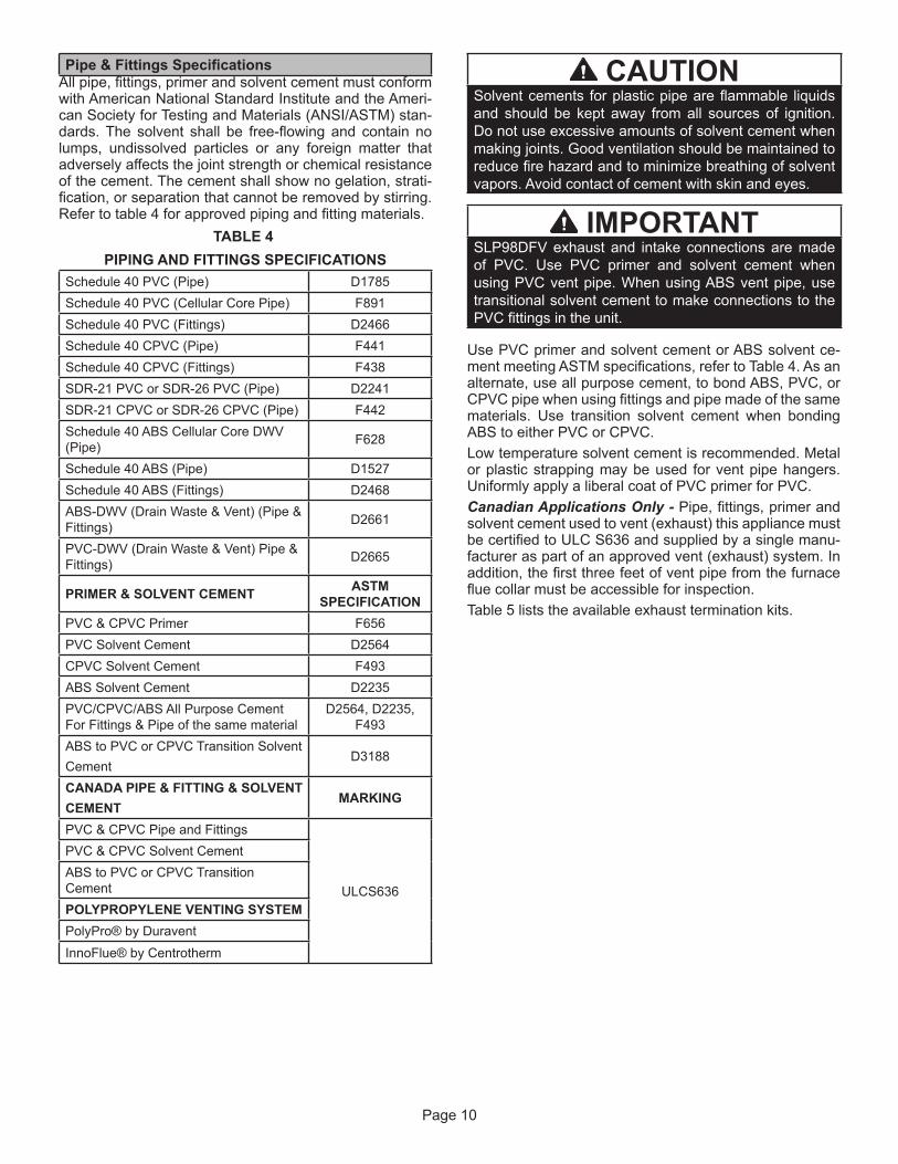
Pipe & Fittings SpecificationsAll pipe, fittings, primer and solvent cement must conform with American National Standard Institute and the Ameri-can Society for Testing and Materials (ANSI/ASTM) stan-dards. The solvent shall be free-flowing and contain no lumps, undissolved particles or any foreign matter that adversely affects the joint strength or chemical resistance of the cement. The cement shall show no gelation, strati-fication, or separation that cannot be removed by stirring. Refer to table 4 for approved piping and fitting materials.
TABLE 4PIPING AND FITTINGS SPECIFICATIONS
Schedule 40 PVC (Pipe) D1785Schedule 40 PVC (Cellular Core Pipe) F891Schedule 40 PVC (Fittings) D2466Schedule 40 CPVC (Pipe) F441Schedule 40 CPVC (Fittings) F438SDR-21 PVC or SDR-26 PVC (Pipe) D2241SDR-21 CPVC or SDR-26 CPVC (Pipe) F442Schedule 40 ABS Cellular Core DWV (Pipe) F628
Schedule 40 ABS (Pipe) D1527Schedule 40 ABS (Fittings) D2468ABS-DWV (Drain Waste & Vent) (Pipe & Fittings) D2661
PVC-DWV (Drain Waste & Vent) Pipe & Fittings) D2665
PRIMER & SOLVENT CEMENT ASTM SPECIFICATION
PVC & CPVC Primer F656PVC Solvent Cement D2564CPVC Solvent Cement F493ABS Solvent Cement D2235PVC/CPVC/ABS All Purpose Cement For Fittings & Pipe of the same material
D2564, D2235, F493
ABS to PVC or CPVC Transition SolventCement
D3188
CANADA PIPE & FITTING & SOLVENTCEMENT
MARKING
PVC & CPVC Pipe and Fittings
ULCS636
PVC & CPVC Solvent CementABS to PVC or CPVC Transition CementPOLYPROPYLENE VENTING SYSTEMPolyPro® by DuraventInnoFlue® by Centrotherm
CAUTIONSolvent cements for plastic pipe are flammable liquids and should be kept away from all sources of ignition. Do not use excessive amounts of solvent cement when making joints. Good ventilation should be maintained to reduce fire hazard and to minimize breathing of solvent vapors. Avoid contact of cement with skin and eyes.
IMPORTANTSLP98DFV exhaust and intake connections are made of PVC. Use PVC primer and solvent cement when using PVC vent pipe. When using ABS vent pipe, use transitional solvent cement to make connections to the PVC fittings in the unit.
Use PVC primer and solvent cement or ABS solvent ce-ment meeting ASTM specifications, refer to Table 4. As an alternate, use all purpose cement, to bond ABS, PVC, or CPVC pipe when using fittings and pipe made of the same materials. Use transition solvent cement when bonding ABS to either PVC or CPVC.Low temperature solvent cement is recommended. Metal or plastic strapping may be used for vent pipe hangers. Uniformly apply a liberal coat of PVC primer for PVC.Canadian Applications Only - Pipe, fittings, primer and solvent cement used to vent (exhaust) this appliance must be certified to ULC S636 and supplied by a single manu-facturer as part of an approved vent (exhaust) system. In addition, the first three feet of vent pipe from the furnace flue collar must be accessible for inspection.Table 5 lists the available exhaust termination kits.

Page 11
TABLE 5 OUTDOOR TERMINATION USAGE*
Input Size Vent Pipe Dia. in.
STANDARD CONCENTRIC
Flush Mount Kit
Wall Kit Wall Ring Kit
Field Fabricated
1-1.2 inch 2 inch 3 inch
2 inch 3 inch 2 inch71M80 (US)
444W92 (CA)
69M29 (US)
444W92 (CA)
60L46 (US) 444W93 (CA)
51W11 (US)
51W12 (CA)
22G44 (US)
430G28 (CA)
44J40 (US)
481J20 (CA)
15F74
0702 3YES YES 1YES 1YES 5YES 2YES
2-1/2 3YES YES 1YES 1YES 5YES 2YES3 3YES YES 1YES 1YES 5YES 2YES
0902 3YES YES YES 5YES YES YES
2-1/2 3YES YES YES 5YES YES YES3 3YES YES YES 5YES YES YES
1102 YES YES YES 5YES YES YES
2-1/2 YES YES 5YES YES YES3 YES YES 5YES YES YES
NOTE - Standard Terminations do not include any vent pipe or elbows external to the structure. Any vent pipe or elbows external to the structure must be included in total vent length calculations. See vent length tables.* Kits must be properly installed according to kit instructions.1Requires field-provided outdoor 1-1/2” exhaust accelerator.2Concentric kits 71M80 and 44W92 include 1-1/2” outdoor accelerator, when used with 070 input models.3 Flush mount kits 51W11 and 51W12 includes 1-1/2 in. outdoor exhaust accelerator, required when used with 070 and 090 input models.4 Termination kits 30G28, 44W92, 4493 and 81J20 are certified to ULC S636 for use in Canada only.5 See table 7 for vent accelerator requirements.
Page 12
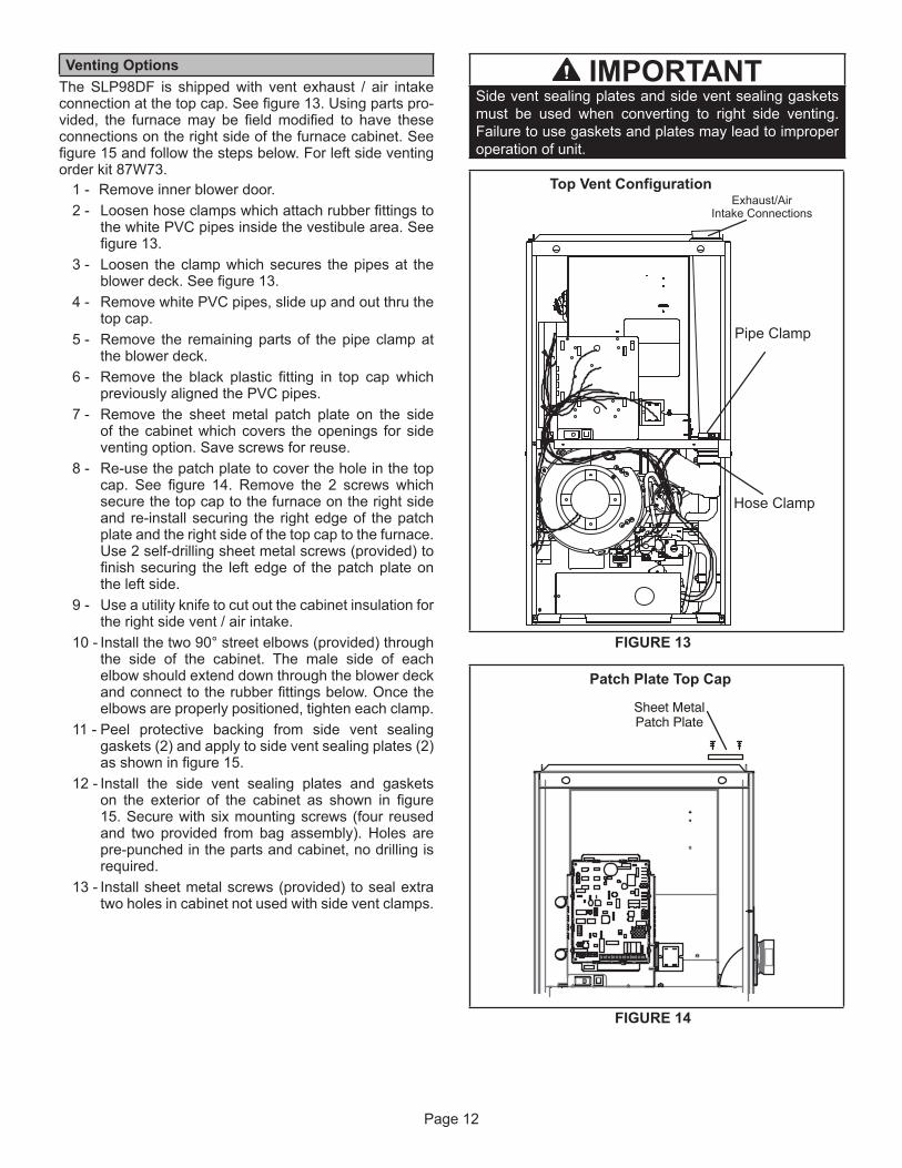
Venting OptionsThe SLP98DF is shipped with vent exhaust / air intake connection at the top cap. See figure 13. Using parts pro-vided, the furnace may be field modified to have these connections on the right side of the furnace cabinet. See figure 15 and follow the steps below. For left side venting order kit 87W73.
1 - Remove inner blower door.2 - Loosen hose clamps which attach rubber fittings to
the white PVC pipes inside the vestibule area. See figure 13.
3 - Loosen the clamp which secures the pipes at the blower deck. See figure 13.
4 - Remove white PVC pipes, slide up and out thru the top cap.
5 - Remove the remaining parts of the pipe clamp at the blower deck.
6 - Remove the black plastic fitting in top cap which previously aligned the PVC pipes.
7 - Remove the sheet metal patch plate on the side of the cabinet which covers the openings for side venting option. Save screws for reuse.
8 - Re-use the patch plate to cover the hole in the top cap. See figure 14. Remove the 2 screws which secure the top cap to the furnace on the right side and re-install securing the right edge of the patch plate and the right side of the top cap to the furnace. Use 2 self-drilling sheet metal screws (provided) to finish securing the left edge of the patch plate on the left side.
9 - Use a utility knife to cut out the cabinet insulation for the right side vent / air intake.
10 - Install the two 90° street elbows (provided) through the side of the cabinet. The male side of each elbow should extend down through the blower deck and connect to the rubber fittings below. Once the elbows are properly positioned, tighten each clamp.
11 - Peel protective backing from side vent sealing gaskets (2) and apply to side vent sealing plates (2) as shown in figure 15.
12 - Install the side vent sealing plates and gaskets on the exterior of the cabinet as shown in figure 15. Secure with six mounting screws (four reused and two provided from bag assembly). Holes are pre-punched in the parts and cabinet, no drilling is required.
13 - Install sheet metal screws (provided) to seal extra two holes in cabinet not used with side vent clamps.
IMPORTANTSide vent sealing plates and side vent sealing gaskets must be used when converting to right side venting. Failure to use gaskets and plates may lead to improper operation of unit.
Top Vent ConfigurationExhaust/Air
Intake Connections
Pipe Clamp
Hose Clamp
FIGURE 13
Sheet MetalPatch Plate
Patch Plate Top Cap
FIGURE 14

Page 13
Right Side Vent Configuration
Side VentSealing Plate
Side VentSealing Gaskets
Street Elbows (2)
IntakeExhaust
FIGURE 15
Joint Cementing ProcedureAll cementing of joints should be done according to these pecifications outlined in ASTM D 2855.NOTE - A sheet metal screw may be used to secure the intake pipe to the connector, if desired. Use a drill or self tapping screw to make a pilot hole.
DANGERDANGER OF EXPLOSION! Fumes from PVC glue may ignite during system check. Allow fumes to dissipate for at least 5 minutes before placing unit into operation.
1 - Measure and cut vent pipe to desired length.2 - Debur and chamfer end of pipe, removing any
ridges or rough edges. If end is not chamfered, edge of pipe may remove cement from fitting socket and result in a leaking joint.
3 - Clean and dry surfaces to be joined.NOTE - Check the inside of vent pipe thoroughly for any obstruction that may alter furnace operation.
4 - Test fit joint and mark depth of fitting on outside of pipe.
5 - Uniformly apply a liberal coat of PVC primer for PVC or use a clean dry cloth for ABS to clean inside socket surface of fitting and male end of pipe to depth of fitting socket.
6 - Promptly apply solvent cement to end of pipe and inside socket surface of fitting. Cement should be applied lightly but uniformly to inside of socket. Take care to keep excess cement out of socket. Apply second coat to end of pipe.
NOTE - Time is critical at this stage. Do not allow primer to dry before applying cement.
7 - Immediately after applying last coat of cement to pipe, and while both inside socket surface and end of pipe are wet with cement, forcefully insert end of pipe into socket until it bottoms out. Turn PVC pipe 1/4 turn during assembly (but not after pipe is fully inserted) to distribute cement evenly. DO NOT turn ABS or cellular core pipe.
NOTE - Assembly should be completed within 20 seconds after last application of cement. Hammer blows should not be used when inserting pipe.
8 - After assembly, wipe excess cement from pipe at end of fitting socket. A properly made joint will show a bead around its entire perimeter. Any gaps may indicate a defective assembly due to insufficient solvent.
9 - Handle joints carefully until completely set.

Page 14
Venting Pracitces
* See Piping and Fittings Specifications table
Piping Suspension Guidelines
NOTE - Isolate piping at the point where it exits the outside wall orroof in order to prevent transmission of vibration to the structure.
SCHEDULE 40PVC - 5'
all other pipe* - 3'
Wall edistuoedisni
24” maximum3/4” minimum
Wall Thickness Guidelines
FIGURE 16
If replacing a furnace which wascommonly vented with another gas appliance, the sizeof the existing vent pipe for that gas appliance must bechecked. Without the heat of the original furnace flueproducts, the existing vent pipe is probably oversized forthe single water heater or other appliance. The ventshould be checked for proper draw with the remainingappliance.
REPLACING FURNACE THAT WAS PART OF ACOMMON VENT SYSTEM
CHIMNEYOR GAS
VENT(Check sizing
for waterheater only)
FURNACE(Replaced)
WATERHEATER
OPENINGS(To Adjacent
Room)
FIGURE 17
1 - n areas where piping penetrates joists or interior walls, hole must be large enough to allow clearance on all sides of pipe through center of hole using a hanger.
2 - When furnace is installed in a residence where unit is shut down for an extended period of time, such as a vacation home, make provisions for draining condensate collection trap and lines.
Exhaust Piping (Figures 19 and 21)
Route piping to outside of structure. Continue with instal-lation following instructions given in piping termination section.
WARNINGCarbon Monoxide Poisoning HazardCutting or altering exhaust or air intake pipes, which are located in the blower compartment, could result in Carbon Monoxide Poisoning or Death.
CAUTIONDo not discharge exhaust into an existing stack or stack that also serves another gas appliance. If vertical discharge through an existing unused stack is required, insert PVC pipe inside the stack until the end is even with the top or outlet end of the metal stack.
CAUTIONThe exhaust vent pipe operates under positive pressure and must be completely sealed to prevent leakage of combustion products into the living space.
Vent piping GuidliensNOTE - Lennox has approved the use of DuraVent® and Centrotherm manufactured vent pipe and terminations as an option to PVC. When using the PolyPro® by Du-raVent or InnoFlue® by Centrotherm venting system the vent pipe requirements stated in the unit installation in-struction – minimum & maximum vent lengths, termination clearances, etc. – apply and must be followed. Follow the instructions provided with PoyPro by DuraVent and Inno-Flue® by Centrotherm venting system for assembly or if requirements are more restrictive. The PolyPro by Du-ravent and InnoFlue by Centrotherm venting system must also follow the uninsulated and unconditioned space crite-ria listed in table 9.The SLP98DFV is installed only as a Direct Vent gas central furnace.
NOTE - In Direct Vent installations, combustion air is tak-en from outdoors and flue gases are discharged outdoors. Intake and exhaust pipe sizing -- Size pipe according to tables 6 and 7. Count all elbows inside and outside the home. Table 6 lists the minimum vent pipe lengths per-mitted. Table 7 lists the maximum pipe lengths permitted.
Page 15
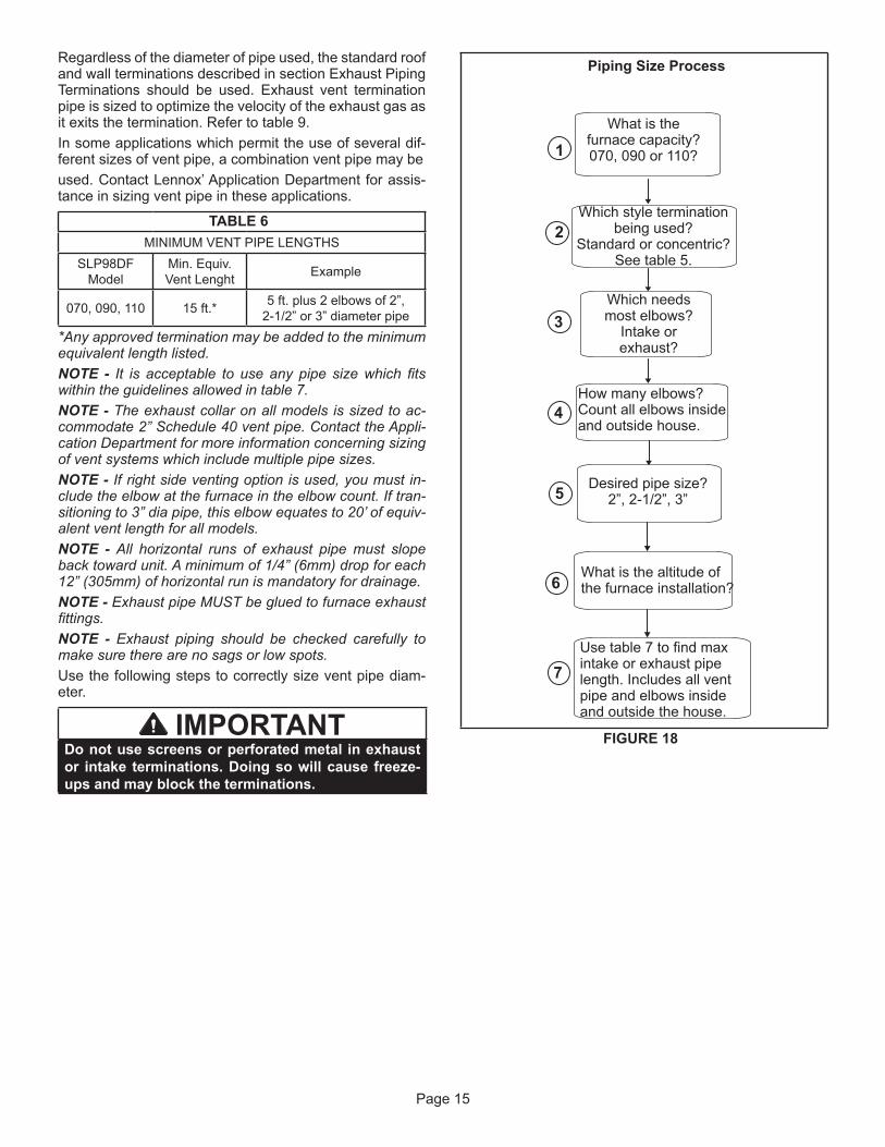
Regardless of the diameter of pipe used, the standard roof and wall terminations described in section Exhaust Piping Terminations should be used. Exhaust vent termination pipe is sized to optimize the velocity of the exhaust gas as it exits the termination. Refer to table 9.In some applications which permit the use of several dif-ferent sizes of vent pipe, a combination vent pipe may beused. Contact Lennox’ Application Department for assis-tance in sizing vent pipe in these applications.
TABLE 6
MINIMUM VENT PIPE LENGTHSSLP98DF
ModelMin. Equiv. Vent Lenght Example
070, 090, 110 15 ft.* 5 ft. plus 2 elbows of 2”, 2-1/2” or 3” diameter pipe
*Any approved termination may be added to the minimum equivalent length listed.NOTE - It is acceptable to use any pipe size which fits within the guidelines allowed in table 7.NOTE - The exhaust collar on all models is sized to ac-commodate 2” Schedule 40 vent pipe. Contact the Appli-cation Department for more information concerning sizing of vent systems which include multiple pipe sizes.NOTE - If right side venting option is used, you must in-clude the elbow at the furnace in the elbow count. If tran-sitioning to 3” dia pipe, this elbow equates to 20’ of equiv-alent vent length for all models.NOTE - All horizontal runs of exhaust pipe must slope back toward unit. A minimum of 1/4” (6mm) drop for each 12” (305mm) of horizontal run is mandatory for drainage.NOTE - Exhaust pipe MUST be glued to furnace exhaust fittings.NOTE - Exhaust piping should be checked carefully to make sure there are no sags or low spots.Use the following steps to correctly size vent pipe diam-eter.
IMPORTANTDo not use screens or perforated metal in exhaust or intake terminations. Doing so will cause freeze-ups and may block the terminations.
Piping Size Process
1
2
3
4
5
6
Which style terminationbeing used?
Standard or concentric?See table 5.
Which needsmost elbows?
Intake orexhaust?
How many elbows?Count all elbows insideand outside house.
Desired pipe size?2”, 2-1/2”, 3”
Use table 7 to find maxintake or exhaust pipelength. Includes all ventpipe and elbows insideand outside the house.
What is the altitude ofthe furnace installation?
7
What is thefurnace capacity?070, 090 or 110?
FIGURE 18

Page 16
TABLE 7 Maximum Allowable Intake or Exhaust Vent Length in Feet
*Size intake and exhaust pipe length separately. Values in table are for Intake OR Exhaust, not combined total. Both Intake and Exhaust must be same pipe size.NOTE - Additional vent pipe and elbows used to terminate the vent pipe outside the structure must be included in the total vent length calculation.
Standard Termination at Elevation 0 - 4500’Number
Of 90̊̊ Elbows Used
2” Pipe 2-1/2” Pipe 3” PipeModel Model Model
070 090 110 135 070 090 110 135 070 090 110 135
1 91 69 14
N/A
140 93 43
N/A
162 143 118
N/A
2 86 64 9 135 88 38 157 138 1133 81 59
N/A
130 83 33 152 133 1084 76 54 125 78 28 147 128 1035 71 49 120 73 23 142 123 986 66 44 115 68 18 137 118 937 61 39 110 63 13 132 113 888 56 34 105 58
N/A127 108 83
9 51 29 100 53 122 103 7810 46 24 95 48 117 98 73
Standard Termination at Elevation 4501’ - 7500’Number
of 90̊ Elbows Used
2” Pipe 2-1/2” Pipe 3” PipeModel Model Model
070 090 110 135 070 090 110 135 070 090 110 135
1 66 69 14
N/A
115 93 43
N/A
137 143 118
N/A
2 61 64 110 88 132 138 1139 383 56 59 105 83 127 133 108
N/A
334 51 54 100 78 122 128 103285 46 49 95 73 23 117 123 986 41 44 90 68 18 112 118 937 36 39 85 63 107 113 88138 31 34 80 58 102 108 83
299 26 75 53 97 103 782410 21 70 48 92 98 73
Standard Termination 7501’ - 10,000”Number
of 90̊ Elbows Used
2” Pipe 2-1/2” Pipe 3” PipeModel Model Model
070 090 110 135 070 090 110 135 070 090 110 135
1 41 44
N/A N/A
90 68
N/A N/A
112 118 93
N/A
2 36 39 85 63 107 113 883 31 34 80 58 102 108 834 26 29 75 53 97 103 785 21 24 70 48 92 98 736 16 19 65 43 87 93 687 11 14 60 38 82 88 638
N/A N/A55 33 77 83 58
9 50 28 72 78 5310 45 23 67 73 48
NOTE - Table 7 continued on next page with concentric terminations.

Page 17
TABLE 7Maximum Allowable Intake or Exhaust Vent Length in Feet
*Size intake and exhaust pipe length separately. Values in table are for Intake OR Exhaust, not combined total. Both Intake and Exhaust must be same pipe size.
Concentric Termination at Elevation 0 - 4500’Number
Of 90̊̊ Elbows Used
2” Pipe 2-1/2” Pipe 3” PipeModel Model Model
070 090 110 135 070 090 110 135 070 090 110 135
1 83 67 12
N/A
130 89 39
N/A
146 139 114
N/A
2 78 62 7 125 84 34 141 134 1093 73 57
N/A
120 79 29 136 129 1044 68 52 115 74 24 131 124 995 63 47 110 69 19 126 119 946 58 42 105 64 14 121 114 897 53 37 100 59
N/A
116 109 848 48 32 95 54 111 104 799 43 27 90 49 106 99 74
10 38 22 85 44 101 94 69Concentric Termination at Elevation 4501’ - 7500’
Number of 90̊
Elbows Used
2” Pipe 2-1/2” Pipe 3” PipeModel Model Model
070 090 110 135 070 090 110 135 070 090 110 135
1 58 67 12
N/A
105 89 39
N/A
121 114 114
N/A
2 53 62 100 84 116 109 1097 343 48 57 95 79 111 104 104
N/A
294 43 52 90 74 106 99 99245 38 47 85 69 19 101 94 946 33 42 80 64 14 96 89 897 28 37 75 59 91 84 84
N/A8 23 32 70 54 86 79 79279 18 65 49 81 74 742210 13 60 44 76 69 69
Concentric Termination 7501’ - 10,000”Number
of 90̊ Elbows Used
2” Pipe 2-1/2” Pipe 3” PipeModel Model Model
070 090 110 135 070 090 110 135 070 090 110 135
1 33 42
N/A N/A
80 64
N/A N/A
96 114 89
N/A
2 28 37 75 59 91 109 843 23 32 70 54 86 104 794 18 27 65 49 81 99 745 13 22 60 44 76 94 696
N/A
17 55 39 71 89 647 12 50 34 66 84 598
N/A45 29 61 79 54
9 40 24 56 74 4910 35 19 51 69 44

Page 18
TYPICAL EXHAUST PIPE CONNECTIONS AND CONDENSATE TRAP INSTALLATION
TRANSITION
2”2”2”
3”
TOP VIEW
ExhaustAir Intake
DO NOT transitionfrom smaller to largerpipe size in horizontalruns of exhaust pipe.
* When transitioning up in pipe size, use the shortest length of 2” PVC pipe possible.NOTE − Exhaust pipe and intake pipe must be the same diameter.
*2“
FIGURE 19
TYPICAL AIR INTAKE PIPE CONNECTIONS
2”2”
TRANSITION
3”
TRANSITION
2”
3”
TOP VIEW
ExhaustAir Intake
*2”*2”
*2”
* When transitioning up in pipe size, use the shortest length of 2” PVC pipe possible.NOTE − Intake pipe and exhaust pipe must be the same diameter.
FIGURE 20

Page 19
TYPICAL EXHAUST CONNECTIONS WITH RIGHT SIDE VENT OPTION
TRANSITION
2” 3”
TOP VIEW
*2”
* When transitioning up in pipe size, use the shortest length of 2” PVC pipe possible.NOTE Intake pipe and exhaust pipe must be the same diameter.
Pipe Length4” Maximum
(Not Furnished)2”
2”
Plate(Furnished)Street Ell
(Not Furnished)
FIGURE 21
TRANSITION
2” 3”
TOP VIEW
*2”
* When transitioning up in pipe size, use the shortest length of 2” PVC pipe possible.NOTE Intake pipe and exhaust pipe must be the same diameter.
2”
Plate(Furnished)
TYPICAL AIR INTAKE PIPE CONNECTIONS WITH RIGHT SIDE VENT OPTION
*2”
Street Ell(Not Furnished)
FIGURE 22

Page 20
FIGURE 23
VENT TERMINATION CLEARANCESFOR DIRECT VENT INSTALLATIONS IN THE USA AND CANADA
K
D
E
L
B
C
F
G
A
B
JA
M
I
H
INSIDE CORNERDETAIL
VENT TERMINAL AIR SUPPLY INLET AREA WHERE TERMINALIS NOT PERMITTED
FixedClosedOperable
B
FixedClosed
Operable
B
B
A =
B =
C =
D =
E =F =G =H =
I =
J =
K =
L =
M =
US Installations1 Canadian Installations2
12 inches (305mm) or 12 in. (305mm)above average snow accumulation.
12 inches (305mm) or 12 in. (305mm)above average snow accumulation.
Clearance above grade, veranda,porch, deck or balcony
Clearance to window ordoor that may be opened
6 inches (152mm) for appliances <10,000
pliances > 10,000 Btuh (3kw) and <50,000
pliances > 50,000 Btuh (15kw)
6 inches (152mm) for appliances <10,000Btuh (3kw), 12 inches (305mm) for appliances > 10,000 Btuh (3kw) and
<100,000 Btuh (30kw), 36 inches (.9m)for appliances > 100,000 Btuh (30kw)
Clearance to permanentlyclosed window
Vertical clearance to ventilated soffit located above the terminal within a
horizontal distance of 2 feet (610mm)from the center line of the terminal
Clearance to unventilated soffitClearance to outside cornerClearance to inside corner
tended above meter / regulator assemblyClearance to service regulator
vent outletClearance to non-mechanical air
pliance
ply inletClearance above paved sidewalk or
paved driveway located on public propertyClearance under veranda, porch, deck or balcony
* 12”
*
*
* 7 feet (2.1m)
3 feet (.9m) within a height 15 feet (4.5m)above the meter / regulator assembly
3 feet (.9m)
6 inches (152mm) for appliances <10,000
pliances > 10,000 Btuh (3kw) and <50,000
pliances > 50,000 Btuh (15kw)
6 inches (152mm) for appliances <10,000Btuh (3kw), 12 inches (305mm) for appliances > 10,000 Btuh (3kw) and
<100,000 Btuh (30kw), 36 inches (.9m)for appliances > 100,000 Btuh (30kw)
3 feet (.9m) above if within 10 feet(3m) horizontally
6 feet (1.8m)
7 feet (2.1m)†
12 inches (305mm)‡
1 In accordance with the current ANSI Z223.1/NFPA 54 Natural Fuel Gas Code2 In accordance with the current CSA B149.1, Natural Gas and Propane Installation Code
*For clearances not specified in ANSI Z223.1/NFPA 54 or CSAB149.1, clearance will be in accordance with local installationcodes and the requirements of the gas supplier and theseinstallation instructions.”
† A vent shall not terminate directly above a sidewalk or paved driveway that is locatedbetween two single family dwellings and serves both dwellings. ‡ Permitted only if veranda, porch, deck or balcony is fully open on a minimum oftwo sides beneath the floor. Lennox recommends avoiding this location if possible.
* 12”
* Equal to or greater than soffit depth * Equal to or greater than soffit depth* Equal to or greater than soffit depth
* Equal to or greater than soffit depth * Equal to or greater than soffit depth* No minimum to outside corner * No minimum to outside corner
3 feet (.9m) within a height 15 feet (4.5m)above the meter / regulator assembly
3 feet (.9m)
*
*12 inches (305mm)‡
Page 21
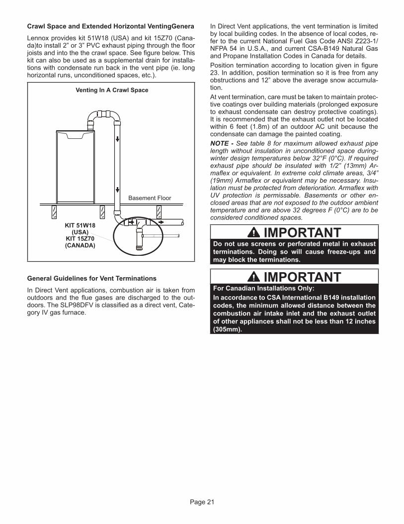
Crawl Space and Extended Horizontal VentingGenera
Lennox provides kit 51W18 (USA) and kit 15Z70 (Cana-da)to install 2” or 3” PVC exhaust piping through the floor joists and into the the crawl space. See figure below. This kit can also be used as a supplemental drain for installa-tions with condensate run back in the vent pipe (ie. long horizontal runs, unconditioned spaces, etc.).
Venting In A Crawl Space
KIT 51W18(USA)
Basement Floor
KIT 15Z70(CANADA)
General Guidelines for Vent Terminations
In Direct Vent applications, combustion air is taken from outdoors and the flue gases are discharged to the out-doors. The SLP98DFV is classified as a direct vent, Cate-gory IV gas furnace.
In Direct Vent applications, the vent termination is limited by local building codes. In the absence of local codes, re-fer to the current National Fuel Gas Code ANSI Z223-1/NFPA 54 in U.S.A., and current CSA-B149 Natural Gas and Propane Installation Codes in Canada for details.Position termination according to location given in figure 23. In addition, position termination so it is free from any obstructions and 12” above the average snow accumula-tion.At vent termination, care must be taken to maintain protec-tive coatings over building materials (prolonged exposure to exhaust condensate can destroy protective coatings). It is recommended that the exhaust outlet not be located within 6 feet (1.8m) of an outdoor AC unit because the condensate can damage the painted coating.NOTE - See table 8 for maximum allowed exhaust pipe length without insulation in unconditioned space during-winter design temperatures below 32°F (0°C). If required exhaust pipe should be insulated with 1/2” (13mm) Ar-maflex or equivalent. In extreme cold climate areas, 3/4” (19mm) Armaflex or equivalent may be necessary. Insu-lation must be protected from deterioration. Armaflex with UV protection is permissable. Basements or other en-closed areas that are not exposed to the outdoor ambient temperature and are above 32 degrees F (0°C) are to be considered conditioned spaces.
IMPORTANTDo not use screens or perforated metal in exhaust terminations. Doing so will cause freeze-ups and may block the terminations.
IMPORTANTFor Canadian Installations Only:In accordance to CSA International B149 installation codes, the minimum allowed distance between the combustion air intake inlet and the exhaust outlet of other appliances shall not be less than 12 inches (305mm).

Page 22
TABLE 8 Maximum Allowable Vent Pipe Length (in ft.) Without Insulation In Unconditioned Space
For Winter Design Temperatures Modulating High Efficiency FurnaceWinter DesignTemperatures1
°F (°C)
Vent PipeDiameter
Unit Input Size
070 090 110 135
32 to 21 (0 to -6)
PVC 2PP PVC 2PP PVC 2PP PVC 2PP2 in. 11 9 14 12 18 15
N/A N/A2-1/2 in 7
N/A
10 N/A 12 N/A3 in.
N/A
6 6 8 8 13 13
20 to 1 (-7 to -17)
2 in. 6 4 8 6
N/A N/A
2-1/2 in.
N/A N/A N/A N/A3 in.
0 to -20 (-18 to -29)
2 in.2-1/2 in.
3 in.1Refer to 99% Minimum Design Temperature table provided in the current edition of the ASHRAE Fundamentals Handbook.2 Poly-Propylene vent pipe (PP) by Duravent and Centrotherm.NOTE - Concentric terminations are the equivalent of 5’ and should be considered when measuring pipe length.NOTE - Maximum uninsulated vent lengths listed may include the termination(vent pipe exterior to the structure) and cannot exceed 5 linear feet or themaximum allowable intake or exhaust vent length listed in table 7 which ever is less.NOTE - If insulation is required in an unconditioned space, it must be located on the pipe closest to the furnace. See figure24.
ConditionedSpace Unconditioned
Space
ExhaustPipe
IntakePipe
ConditionedSpace
Pipe Insulation
FIGURE 24

Page 23
Details of Intake and Exhaust Piping Terminations for Direct Vent Installations
NOTE - In Direct Vent installations, combustion air is taken from outdoors and flue gases are discharged to outdoors.NOTE - Flue gas may be slightly acidic and may adverse-ly affect some building materials. If any vent termination is used and the flue gasses may impinge on the building material, a corrosion-resistant shield (minimum 24 inches square) should be used to protect the wall surface. If the optional tee is used, the protective shield is recommend-ed. The shield should be constructed using wood, plastic, sheet metal or other suitable material. All seams, joints, cracks, etc. in the affected area should be sealed using an appropriate sealant. See figure 33.Intake and exhaust pipes may be routed either horizon-tally through an outside wall or vertically through the roof. In attic or closet installations, vertical termination through the roof is preferred. Figures 25 through 30 show typical terminations.
1 - Intake and exhaust terminations are not required to be in the same pressure zone. You may exit the intake on one side of the structure and the exhaust on another side (figure 26). You may exit the exhaust out the roof and the intake out the side of the structure (figure 27).
2 - Intake and exhaust pipes should be placed as close together as possible at termination end (refer to illustrations). Maximum separation is 3” (76mm) on roof terminations and 6” (152mm) on side wall terminations.
NOTE - When venting in different pressure zones, the maximum separation requirement of intake and exhaust pipe DOES NOT apply.
3 - On roof terminations, the intake piping should terminate straight down using two 90° elbows (See figure 25).
4 - Exhaust piping must terminate straight out or up as shown. A reducer may be required on the exhaust piping at the point where it exits the structure to improve the velocity of exhaust away from the intake piping. See table 9.
NOTE - Care must be taken to avoid recirculation of ex-haust back into intake pipe.
TABLE 9
EXHAUST PIPE TERMINATION SIZE REDUCTIONSLP98DFV Model Termination Pipe Size
*070 1-1/2”*090 2”110 2”
*SLP98DF -070 and -090 units with the flush-mount ter-mination must use the 1-1/2” accelerator supplied with the kit.
5 - On field-supplied terminations for side wall exit, exhaust piping may extend a maximum of 12 inches (305mm) for 2” PVC and 20 inches (508mm) for 3” (76mm) PVC beyond the outside wall. Intake piping should be as short as possible. See figure 33.
6 - On field-supplied terminations, a minimum distance between the end of the exhaust pipe and the end of the intake pipe without a termination elbow is 8” and a minimum distance of 6” with a termination elbow. See figure 33.
UNCONDITIONEDATTIC SPACE
SIZE TERMINATIONPIPE PER TABLE 7.
3”(76mm) MAX.
12” (305mm) ABOVEAVERAGE SNOWACCUMULATION
3” (76mm) OR2” (51mm) PVC
PROVIDE SUPPORTFOR INTAKE ANDEXHAUST LINES
8” (203mm) MIN
Inches(mm)
DIRECT VENT ROOF TERMINATION KIT(15F75 or 44J41)
FIGURE 25
ExhaustPipe
Furnace
Exiting Exhaust and Intake Vent(different pressure zone)
Inlet Air(Minimum 12 in.305 MM) abovegrade or snowaccumulation
FIGURE 26
Roof TerminatedExhaust Pipe
Furnace
Exiting Exhaust and Intake Vent(different pressure zone)
Inlet Air(Minimum 12 in.305 MM) abovegrade or snowaccumulation
FIGURE 27

Page 24
7 - If intake and exhaust piping must be run up a side wall to position above snow accumulation or other obstructions, piping must be supported. At least one bracket must be used within 6” from the top of the elbow and then every 24” (610mm) as shown in figure 33, to prevent any movement in any direction. When exhaust and intake piping must be run up an outside wall, the exhaust piping must be terminated with pipe sized per table 9.The intake piping may be equipped with a 90° elbow turndown. Using turndown will add 5 feet (1.5m) to the equivalent length of the pipe.
8 - Based on the recommendation of the manufacturer, a multiple-furnace installation may use a group of up to four terminations assembled together horizontally, as shown in figure 31.
DIRECT VENT CONCENTRIC ROOFTOP TERMINATION71M80, 69M29 or 60L46 (US)44W92 or 44W93 (Canada)
MinimumAbove Average
SnowAccumulation
SHEET METAL STRAP(Clamp and sheet metal strap
must be field−installed to supportthe weight of the termination kit.)
FLASHING(Not Furnished)
CLAMPFIELD-PROVIDED
REDUCER MAY BE REQUIREDTO ADAPT LARGER VENT
PIPE SIZE TO TERMINATION
INTAKE12” (305mm)
FIGURE 28
12” (305mm) Min.above grade or
cumulation.
DIRECT VENT CONCENTRIC WALL TERMINATION71M80, 69M29 or 60L46 (US)41W92 or 41W93 (Canada)
INTAKEAIR
EXHAUSTAIR
INTAKEAIR
INTAKEAIR
EXHAUSTAIR
OUTSIDEWALL
GRADE
CLAMP(Not Furnished)
FIELD-PROVIDED
QUIRED TO ADAPTLARGER VENT PIPE
SIZE TO TERMINATION.
FIGURE 29
2” EXTENSION FOR 2” PVCPIPE1” EXTENSION FOR 3”PVC PIPE
1-1/2” ACCELERATOR
FURNACEEXHAUST
PIPE
FURNACEINTAKE
PIPE
4''
GLUE EXHAUSTEND FLUSH INTO
TERMINATION
FLATSIDE
FLUSH-MOUNT SIDE WALL TERMINATION KIT 51W11 (US) or 51W12 (Canada)
FIGURE 30
EXHAUSTVENT
INTAKEAIR
5-1/2”(140mm)
Front View
12”(305mm)
5”(127mm)
18” MAX.(457mm)
EXHAUST VENT
INTAKEAIR
OPTIONAL VENT TERMINATION FOR MULTIPLE UNITINSTALLATION OF DIRECT VENT WALL TERMINATION KIT
(30G28 or 81J20)
Inches (mm)
Side View
12” (305mm) Min.above grade or
cumulation.
optional intake elbow
FIGURE 31
SLP98 DIRECT VENT APPLICATIONUSING EXISTING CHIMNEY
NOTE - Do tical discharge through an existing unused chimney or stack is required, insert pipinginside trated. In any exterior portion of chimney, the exhaust vent must be insulated.
8” - 12”(203mm - 305mm)
3” - 8”(76mm-203mm)
3” - 8”(76mm-203mm)
STRAIGHT-CUT ORANGLE-CUT IN DIRECTION
OF ROOF SLOPE *
SHOULDER OF FITTINGSPROVIDE SUPPORT
OF PIPE ON TOP PLATEALTERNATEINTAKE PIPE
INTAKE PIPEINSULATION (optional)
EXTERIORPORTION OF
CHIMNEY
INSULATETO FORM
SEAL
SHEETMETAL TOP
PLATE
*SIZE TERMINATIONPIPE PER TABLE 9.
Minimum 12” (305MM)above chimney top
plate or average snowaccumulation
FIGURE 32

Page 25
FIGURE 33
* Use wall support every 24” (610 mm). Use two wall supports if extension is greater than 24” (610 mm) but less than 48” (1219 mm).
NOTE − One wall support must be within 6” (152 mm)from top of each pipe (intake and exhaust) to preventmovement in any direction.
NOTE − FIELD−PROVIDEDREDUCER MAY BE
REQUIRED TO ADAPTLARGER VENT PIPE SIZE
TO TERMINATION
STRAIGHTAPPPLICATION
EXTENDEDAPPLICATION
D
B
D
B
A
2” (51mm)Vent Pipe
3” (76mm)Vent Pipe
A− Minimum clearanceabove grade or average
snow accumulation
B− Maximum horizontal separation between intake and exhaust
D− Maximum exhaustpipe length
E− Maximum wall supportdistance from top of each
pipe (intake/exhaust)
12” (305 mm)
12” (305 mm)
12” (305 mm)
6” (152 mm)6” (152 mm)
6” (152 mm)6” (152 mm)
8” (203 mm)8” (203 mm)
20” (508 mm)
6” (152 mm)6” (152 mm)
Front View ofIntake and Exhaust
Intake Exhaust
A
C
B
1
2
D
A
C 3IntakeElbow
ExhaustB
A
D
2” (51MM)Vent Pipe
3” (76MM)Vent Pipe
A− Clearance abovegrade or average snow
accumulation
B− Horizontalseparation betweenintake and exhaust
C− Minimum fromend of exhaust to
inlet of intake
D− Exhaust pipe length
E− Wall support distancefrom top of each pipe
(intake/exhaust)
12” (305 mm) Min. 12” (305 mm) Min.
6” (152 mm) Min.24” (610 mm) Max.
9” (227 mm) Min.
12” (305 mm) Min.16” (405 mm) Max.
6” (152 mm) Max.
6” (152 mm) Min.24” (610 mm) Max.
9” (227 mm) Min.
12” (305 mm) Min.20” (508 mm) Max.
6” (152 mm) Max.
IntakeElbow
* WALLSUPPORT
B
A
DE
B
DE
A
ALTERNATE TERMINATIONS (TEE & FORTY−FIVE DEGREE ELBOWS ONLY)
D
C
12”
1
2
E
B
A1
2 As required. Flue gas may be acidic and may adversely affect some building materials. If a side wall venttermination is used and flue gases will impinge on the building materials, a corrosion−resistant shield(24 inches square) should be used to protect the wall surface. If optional tee is used, the protective shieldis recommended. The shield should be constructed using wood, sheet metal or other suitable material.All seams, joints, cracks, etc. in affected area, should be sealed using an appropriate sealant.
3 Exhaust pipe 45° elbow can be rotated to the side away from the combustion air inlet to direct exhaust away from adjacent property. The exhaust must never be directed toward the combustion air inlet.
C2 -Minimum from end ofexhaust to inlet of intake
C1 -Minimum from end ofexhaust to inlet of intake
FIELD FABRICATED WALL TERMINATION
C1 C2
C1C2
See maximum allowable venting tables for ventinglengths with this arrangement.
D
C
12”
1
2
E
B
A
The exhaust termination tee should be connected to the 2” or 3” PVC flue pipe as shown in the illustration. Inhorizontal tee applications there must be be a minimum of 3 ft away from covered patios or any living ares andcannot be within 3 ft of a window. Do not use an accelerator in applications that include an exhaust terminationtee. The accelerator is not required.

Page 26
Condensate Piping
This unit is designed for either right- or left-side exit of condensate piping. Refer to figures 34 and 36 and for con-densate trap locations.NOTE - If necessary the condensate trap may be installed up to 5’ away from the furnace. Use PVC pipe to connect trap to furnace condensate outlet. Piping from furnace must slope down a minimum of 1/4” per ft. toward trap.
1 - Determine which side condensate piping will exit the unit, location of trap, field-provided fittings and length of PVC pipe required to reach available drain.
2 - Use a large flat head screw driver or a 1/2” drive socket extension and remove plug (figure 34) from the cold end header box at the appropriate location on the side of the unit. Install provided 3/4 NPT street elbow fitting into cold end header box. Use Teflon tape or appropriate pipe dope
NOTE - Cold end header box drain plugs are factory in-stalled. Check the unused plug for tightness to prevent leakage.
CONDENSATE TRAP AND PLUG LOCATIONS
Trap(same onright side)
Plug(same on left
side)1-1/2 in.
FIGURE 34
3 - Install the cap over the clean out opening at the base of the trap. Secure with clamp. See figure 40.
4 - Install drain trap using appropriate PVC fittings, glue all joints. Glue the provided drain trap as shown in figure 40. Route the condensate line to an open drain.
5 - Figure 37 shows the furnace and evaporator coil using a separate drain. If necessary, the condensate line from the furnace and evaporator coil can drain together. See figures 38 and 39. The field provided vent must be a minimum 1” to a maximum 2” length above the condensate drain outlet connection.
NOTE - If necessary the condensate trap may be installed up to 5 feet away from the furnace. Piping from furnace must slope down a minimum of 1/4” per ft. toward trap.NOTE - Appropriately sized tubing and barbed fitting may be used for condensate drain. Attach to the drain on the trap using a hose clamp. See figure 35.
Field Provided Drain Components
TubingHose Clamp
Barbed Fitting
Elbow
FIGURE 35

Page 27
6 - If unit will be started immediately upon completion of installation, prime trap per procedure outlined in Unit Start-Up section.
Condensate line must slope downward away from the trap to drain. If drain level is above condensate trap, conden-sate pump must be used. Condensate drain line should be routed within the conditioned space to avoid freezing of condensate and blockage of drain line. If this is not possi-ble, a heat cable kit may be used on the condensate trap and line. Heat cable kit is available from Lennox in various lengths; 6 ft. (1.8m) - kit no. 26K68 and 24 ft. (7.3m) - kit no. 26K69.
CONDENSATE TRAP LOCATION(shown with right side exit of condensation)
5’ max.
to drain
1” min.2” max.
Trap can be installed a maximumof 5ft. from furnace (*PVC only)
Field Provided Vent1” min. 2” max. above
condensate drain.
*Piping from furnace must slope down aminimum 1/4” per ft. toward trap
FIGURE 36
Furnace with Evaporator CoilUsing a Separate Drain
Drain
Field Provided Vent1” min. 2” max. above
condensate drain.
CondensateDrain Connection
Evaporator Drain Line(vent required)
FIGURE 37
IMPORTANTWhen combining the furnace and evaporator coil drains together, the A/C condensate drain outlet must be vented to relieve pressure in order for the furnace pressure switch to operate properly.
Furnace with EvaporatorCoil Using a Common Drain
Field Provided Vent1” min. 2” max. above
condensate drain.
Evaporator Drain Line(vent required)
CondensateDrain Connection
FIGURE 38
HorizontalFurnace4” Min. to 5” Max.abovecondensatedrain connection)
FurnaceCondensateDrainConnection
From Evaporator Coil
Optional
Condensate Trap With Optional Overflow Switch
FIGURE 39
CAUTIONDo not use copper tubing or existing copper condensate lines for drain line.

Page 28
FIGURE 40
Drain TrapAssembly
(Furnished)
Vent
Drain TrapClean Out
5 FeetMaximum
Coupling 3/4 inch slip X slip(Not Furnished)
90° Elbow 3/4 inch PVC(Not Furnished)
3/4 inch PVC Pipe(Not Furnished)
1/2 inch PVC Pipe(Not Furnished)
Condensate DrainConnection In Unit
Drain Assembly for 1/2 inch Drain Pipe
90° Elbow 3/4 inch PVC
(Not Furnished)
Coupling 3/4 inch slip X slip(Not Furnished)
ToDrain
ToDrain
90° Elbow 3/4 inch PVC
(Not Furnished)
To
ToDrain
90° Elbow 1/2 inch PVC
(Not Furnished)
1/2 inch PVC Pipe(Not Furnished)
Drain Assembly for 3/4 inch Drain Pipe
Condensate DrainConnection In Unit
Condensate DrainConnection In Unit
Vent
ToDrain
Condensate DrainConnection In Unit
Optional Condensate Drain Connection
OptionalDrainPipingFromTrap
DrainTrap Assembly(Furnished)
DrainTrap Assembly with 1/2 inch PipingDrainTrap Assembly with 3/4 inch Piping
1/2 inch3/4 inch
1 (25 mm) Min.2 (50 mm) Max.Above Top OfCondensate DrainConnection In Unit
1 (25 mm) Min. 2 (50 mm) Max. Above TopOf Condensate Drain Connection In Unit
1 (25 mm) Min. 2 (50 mm) Max. Above TopOf Condensate Drain Connection In Unit
Trap
Vent
ToDrain
7(178)
TRAP / DRAIN ASSEMBLY USING 1/2” PVC OR 3/4” PVC
Adapter 3/4 inch slip X3/4 inch mpt (not furnished)
90° Street Elbow3/4 inch PVC(not furnished)
90° Street Elbow3/4 inch PVC( furnished)
Adapter 3/4 inch slip X3/4 inch mpt (not furnished)

Page 29
Gas Piping
CAUTIONIf a flexible gas connector is required or allowed by the authority that has jurisdiction, black iron pipe shall be installed at the gas valve and extend outside the furnace cabinet.
WARNINGDo not over torque (800 in-lbs) or under torque (350 in-lbs) when attaching the gas piping to the gas valve.
1 - Gas piping may be routed into the unit through either the left or right-hand side. Supply piping enters into the gas valve from the side of the valve as shown in figure 42. Connect the gas supply piping into the gas valve. The maximum torque is 800 in lbs and minimum torque is 350 in lbs when when attaching the gas piping to the gas valve.
2 - When connecting gas supply, factors such as length of run, number of fittings and furnace rating must be considered to avoid excessive pressure drop. Table 10 lists recommended pipe sizes for typical applications.
NOTE - Use two wrenches when connecting gas piping to avoid transferring torque to the manifold.
3 - Gas piping must not run in or through air ducts, clothes chutes, chimneys or gas vents, dumb waiters or elevator shafts. Center gas line through piping hole. Gas line should not touch side of unit. See figure 42.
4 - Piping should be sloped 1/4 inch per 15 feet (6mm per 5.6m) upward toward the gas meter from the furnace. The piping must be supported at proper intervals, every 8 to 10 feet (2.44 to 3.05m), using suitable hangers or straps. Install a drip leg in vertical pipe runs to serve as a trap for sediment or condensate.
5 - A 1/8” N.P.T. plugged tap or pressure post is located on the gas valve to facilitate test gauge connection. See figures 48.
6 - In some localities, codes may require installation of a manual main shut-off valve and union (furnished by installer) external to the unit. Union must be of the ground joint type.
IMPORTANTCompounds used on threaded joints of gas piping must be resistant to the actions of liquified petroleum gases.
MANUAL MAIN SHUT-OFFVALVE WILL NOT HOLD
NORMAL TEST PRESSURECAP FURNACE
ISOLATEGAS VALVE1/8” N.P.T. PLUGGED TAP
FIGURE 41 Leak Check
After gas piping is completed, carefully check all piping connections (factory- and field-installed) for gas leaks. Use a leak detecting solution or other preferred means.The furnace must be isolated from the gas supply system by closing its individual manual shut-off valve during any pressure testing of the gas supply system at pressures less than or equal to 1/2 psig (3.48 kPa, 14 inches w.c.).I
IMPORTANTWhen testing gas lines using pressures in excess of 1/2 psig (3.48 kPa), gas valve must be disconnected and isolated. See figure 41. Gas valves can be damaged if subjected to pressures greater than 1/2 psig (3.48 kPa).
WARNINGFIRE OR EXPLOSION HAZARDFailure to follow the safety warnings exactly could result in serious injury, death, or property damage. Never use an open flame to test for gas leaks. Check all connections using a commercially available soap solution made specifically for leak detection. Some soaps used for leak detection are corrosive to certain metals. Carefully rinse piping thoroughly after leak test has been completed.

Page 30
GROUNDJOINTUNION
AUTOMATICGAS VALVE(with manual
shut-off valve)
FIELDPROVIDED
AND INSTALLED
GROUNDJOINTUNION
Left Side Piping(Standard)
Right Side Piping(Alternate)
AUTOMATICGAS VALVE(with manual
shut-off valve)
DRIP LEG
DRIP LEG
MANUALMAIN SHUT-OFF
VALVE(1/8 in. NPT
plugged tap shown)
MANUALMAIN SHUT-OFF
VALVE(1/8 in. NPTplugged tap
shown)
NOTE - BLACK IRON PIPE ONLY TO BE ROUTED INSIDE OF CABINET
FIGURE 42
TABLE 10 Gas Pipe Capacity - ft3/hr (m3/hr)
Nominal Iron Pipe
Size Inches (mm)
Internal Diameter
inches (mm)
Length of Pipe - feet (m)
10 (3.048)
20 (6.096)
30 (9,144)
40 (12,192)
50 (15.240)
60 (18.288)
70 (21.336)
80 (24.384)
90 (27.432)
100 (30,480)
1/2 (12.7)
.622 (17.799)
172 (4.87)
118 (3.34)
95 (2.69)
81 (2.29)
72 (2.03)
65 (1.84)
60 (1.69)
56 (1.58)
52 (1.47)
50 (1.42)
3/4 (19.05)
.824 (20.930)
360 (10.19)
247 (7.000)
199 (5.63)
170 (4.81)
151 (4.23)
137 (3.87)
126 (3.56)
117 (3.31)
110 (3.11)
104 (2.94)
1 (25.4)
1.049 (26.645)
678 (19.19)
466 (13.19)
374 (10.59)
320 (9.06)
284 (8.04)
257 (7.27)
237 (6.71)
220 (6.23)
207 (5.86)
195 (5.52)
1-1/4 (31.75)
1.380 (35.052)
1350 (38.22)
957 (27.09)
768 (22.25)
657 (18.60)
583 (16.50)
528 (14.95)
486 (13.76)
452 (12.79)
424 (12.00)
400 (11.33)
1-1/2 (38.1)
1.610 (40.894)
2090 (59.18)
1430 (40.49)
1150 (32.56)
985 (27.89)
873 (24.72)
791 (22.39)
728 (20.61)
677 (19.17)
635 (17.98)
600 (17.00)
2 (50.8)
2.067 (52.502)
4020 (113.83)
2760 (78.15)
2220 (62.86)
1900 (53.80)
1680 (47.57)
1520 (43.04)
1400 (39.64)
1300 (36.81)
1220 (34.55)
1160 (32.844)
2-1/2 (63.5)
2.469 (67.713)
6400 (181.22)
4400 (124.59)
3530 (99.95)
3020 (85.51)
2680 (75.88)
2480 (70.22)
2230 (63.14)
2080 (58.89)
1950 (55.22)
1840 (52.10)
3 (76.2)
3.068 (77.927)
11300 (319.98)
7780 (220.30)
6250 (176.98)
5350 (151.49)
4740 (134.22)
4290 (121.47)
3950 (111.85)
3670 (103.92)
3450 (97.69)
3260 (92.31)
NOTE - Capacity given in cubic feet (m3 ) of gas per hour and based on 0.60 specific gravity gas.
Removal of the Furnace from Common Vent
In the event that an existing furnace is removed from a venting system commonly run with separate gas applianc-es, the venting system is likely to be too large to properly vent the remaining attached appliances.Conduct the following test while each appliance is oper-ating and the other appliances (which are not operating) remain connected to the common venting system. If the venting system has been installed improperly, you must correct the system as indicated in the general venting re-quirements section.

Page 31
WARNINGCARBON MONOXIDE POISONING HAZARDFailure to follow the steps outlined below for each appliance connected to the venting system being placed into operation could result in carbon monoxide poisoning or death.The following steps shall be followed for each appliance connected to the venting system being placed into operation, while all other appliances connected to the venting system are not in operation:
1 - Seal any unused openings in the common venting system.
2 - Inspect the venting system for proper size and horizontal pitch. Determine that there is no blockage, restriction, leakage, corrosion, or other deficiencies which could cause an unsafe condition.
3 - Close all building doors and windows and all doors between the space in which the appliances remaining connected to the common venting system are located and other spaces of the building. Turn on clothes dryers and any appliances not connected to the common venting system. Turn on any exhaust fans, such as range hoods and bathroom exhausts, so they will operate at maximum speed. Do not operate a summer exhaust fan. Close fireplace dampers.
4 - Follow the lighting instructions. Turn on the appliance that is being inspected. Adjust the thermostat so that the appliance operates continuously.
5 - After the main burner has operated for 5 minutes, test for leaks of flue gases at the draft hood relief opening. Use the flame of a match or candle.
6 - After determining that each appliance connected to the common venting system is venting properly, (step 3) return all doors, widows, exhaust fans, fireplace dampers, and any other gas-burning appliances to their previous mode of operation.
7 - If a venting problem is found during any of the preceding tests, the common venting system must be modified to correct the problem. Resize the common venting system to the minimum vent pipe size determined by using the appropriate tables in Appendix G. (These are in the current standards of the National Fuel Gas Code ANSI Z223.1.

Page 32
ElectricalELECTROSTATIC DISCHARGE (ESD)
Precautions and Procedures
CAUTIONElectrostatic discharge can affect electronic components. Take precautions during furnace installation and service to protect the furnace’s electronic controls. Precautions will help to avoid control exposure to electrostatic discharge by putting the furnace, the control and the technician at the same electrostatic potential. Neutralize electrostatic charge by touching hand and all tools on an unpainted unit surface, such as the gas valve or blower deck, before performing any service procedure.
WARNINGElectric Shock Hazard. Can causeinjury or death. Unit must be properly grounded in accordance with national and local codes.
WARNINGFire Hazard. Use of aluminum wire with this product may result in a fire, causing property damage, severe injury or death. Use copper wire only with this product.
CAUTION. Failure to use properly sized wiring and circuit breaker may result in property damage. Size wiring and circuit breaker(s) per Product Specifications bulletin (EHB) and unit rating plate.
MAKE-UPBOX
OUTSIDECABINET
Right Side
EXTERIOR MAKE-UP BOX(FIELD PROVIDED RIGHT SIDE)
FIGURE 43
The unit is equipped with a make-up box on the left hand side of the cabinet. A field-provided make-up box can be installed on the exterior of the right side of the furnace to facilitate installation. If the make-up box is moved to the right side, clip the wire ties that bundle the wires together and install on the outside of the cabinet. See figure 43. The excess wire must be pulled into the blower compart-ment. Secure the excess wire to the existing harness to protect it from damage.Refer to figure 46 for unit field wiring. See figures 44 and 45 for icomfort Wi-Fi thermostat wiring in communicating applications. Table 14 shows DIP switch and on-board link settings for non-communicating thermostat applications. Typical wiring schematic is shown in figure 46.
1 - The power supply wiring must meet Class I restrictions. Protected by either a fuse or circuit breaker, select circuit protection and wire size according to unit nameplate.
NOTE - Unit nameplate states maximum current draw. See table for maximum over-current protection.
TABLE 11
SL98DF Model Maximum Over-Current Protection (Amps)
07036B, 09036C, 0904BC 15
09060C, 11060C 20
2 - Holes are on both sides of the furnace cabinet to facilitate wiring.
3 - Install a separate (properly sized) disconnect switch near the furnace so that power can be turned off for servicing.
4 - Before connecting the thermostat or the power wiring, check to make sure the wires will be long enough for servicing at a later date. Remove the blower access panel to check the length of the wire.
5 - Complete the wiring connections to the equipment. Use the provided unit wiring diagram and field wiring diagram shown in figure 46 and table 14. Use 18-gauge wire or larger that is suitable for Class II rating for thermostat connections.
NOTE - Do NOT make a wire connection between the room thermostat L terminal and the L terminal of the SLP98DFV integrated control unless this is a communi-cating thermostat installation with a noncommunicating outdoor unit.
6 - Electrically ground the unit according to local codes or, in the absence of local codes, according to the current National Electric Code (ANSI/NFPA No. 70) for the USA and current Canadian Electric Code part 1 (CSA standard C22.1) for Canada. A green ground

Page 33
7 - One line voltage “EAC” 1/4” spade terminal is provided on the furnace integrated control. Any electronic air cleaner rated up to one amp can be connected to this terminal with the neutral leg of the circuit being connected to one of the provided neutral terminals. See figure 47 for location of terminal. This terminal is energized when the indoor blower is operating.
8 - One line voltage “HUM” 1/4” spade terminal is provided on the furnace integrated control. Any humidifier rated up to one amp can be connected to this terminal with the neutral leg of the circuit being connected to one of the provided neutral terminals. See figure 47 for location of terminal. This terminal is energized in the heating mode when the indoor blower is is operating.
9 - One 24V “H” terminal is provided on the furnace integrated control terminal block. Any humidifier rated up to 0.5 amp can be connected to this terminal with the ground leg of the circuit being connected to either ground or the “C” terminal. See figure 47 for location of terminal.
10 - Install the room thermostat according to the instructions provided with the thermostat. See table 14 for thermostat connections. If the furnace is being matched with a heat pump, refer to the instruction packaged with the dual fuel thermostat.
NOTE - The discharge air temperature sensor is intended to be mounted downstream of the heat exchanger and air conditioning coil. It must be placed in free airflow, where other accessories (humidifiers, UV lights etc.) will not in-terfere with its accuracy. Wiring distance between the fur-nace and discharge air sensor should not exceed 10 ft. when wired with 18-gauge thermostat wire.
TABLE 12
Run Length — Non CommunicatingWire Run Length AWG# Insulation/Core Types
Less than 100’ (30m) 18 Color-coded, temperature rating 95ºF (35ºC) minimum, solid core. (Class II rated wiring)
More than 100’ (30m) 16
TABLE 13
Run Length — CommunicatingWire Run Length AWG# Insulation/Core Types
Maximum length of wiring for all connections on the RSBus is limited to 1500 feet (457 meters).
18
Color-coded, temperature rating 95ºF (35ºC) minimum, solid core. (Class II rated wiring)
Thermostat Selection
The SLP98DFV is designed to operate in a variable rate capacity mode using a two-stage thermostat. The SLP98DFV will automatically adjust firing rate based upon thermostat cycle times.The icomfort Wi-Fi® thermostat must be used in commu-nicating applications. Refer to the instructions provided with the thermostat for installation, set-up and operationFor optimal performance in non-communicating applica-tions, Lennox recommends use of a ComfortSense® 7000high quality electronic digital thermostat or any other with adjustable settings for 1st stage / 2nd stage on / off differ-entials and adjustable stage timers.Lennox recommends the following two-stage thermostat set-up for optimal variable rate capacity mode: First heat stage differential set to 1/2 to 1 degree F; second heat stage differential set to 1/2 or 1 degree F; second heat stage upstage timer disabled, or set to maximum (1 hr minimum).Indoor Blower Speeds
NOTE - When the SLP98DFV is used with icomfort Wi-Fi® thermostat, proper indoor blower speed selections are made by the communicating thermostat.
1 - When the thermostat is set to “FAN ON,” the indoor blower will run continuously at a percentage of the second- stage cooling speed when there is no cooling or heating demand. The percentage is set using DIP switches 6 and 7.
2 - When the SLP98DFV is running in the heating mode, the integrated control will automatically adjust the blower speed to match the furnace firing rate. This speed can be adjusted up or down by 7.5% or 15% using DIP switches 14 through 16 for the low heat speed and 17 through 19 for the high heat speed.
3 - When there is a cooling demand, the indoor blower will run on the cooling speed designated by the positions of DIP switches 8 through 11.
Generator Use - Voltage Requirements
The following requirements must be kept in mind when specifying a generator for use with this equipment:
• The furnace requires 120 volts + 10% (Range: 108 volts to 132 volts).
• The furnace operates at 60 Hz + 5% (Range: 57 Hz to 63 Hz).
• The furnace integrated control requires both po-larity and proper ground. Both polarity and proper grounding should be checked before attempting to operate the furnace on either permanent or tempo-rary power.
• Generator should have a wave form distortion of less than 5% THD (total harmonic distortion).
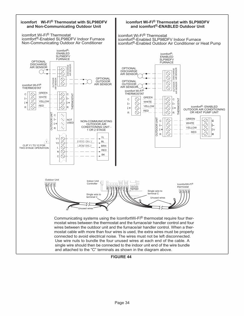
Page 34
FIGURE 44
icomfort Wi-Fi® Thermostat with SLP98DFVand Non-Communicating Outdoor Unit
icomfort®-ENABLEDSLP98DFVFURNACE
icomfort Wi-Fi®THERMOSTAT
NON-COMMUNICATINGOUTDOOR AIR
CONDITIONING UNIT -1 OR 2 STAGE
icomfort Wi-Fi® Thermostaticomfort®-Enabled SLP98DFV Indoor FurnaceNon-Communicating Outdoor Air Conditioner
OPTIONALOUTDOOR
AIR SENSOR
OPTIONALDISCHARGEAIR SENSOR
icomfort Wi-Fi® Thermostat with SLP98DFVand icomfort®-ENABLED Outdoor Unit
icomfort Wi-Fi® Thermostaticomfort®-Enabled SLP98DFV Indoor Furnaceicomfort®-Enabled Outdoor Air Conditioner or Heat Pump
icomfort®-ENABLEDSLP98DFVFURNACE
icomfort®- ENABLEDOUTDOOR AIR CONDITIONING
OR HEAT PUMP UNIT
OPTIONALOUTDOOR
AIR SENSOR
OPTIONALDISCHARGEAIR SENSOR
CLIP Y1 TO Y2 FORTWO-STAGE OPERATION
icomfort Wi-Fi®THERMOSTAT
Indoor UnitController
Outdoor Unit
IcomfortWi-Fi®thermostat
Single wire toterminal C
Single wire toterminal C
Unused wires
Unused wires
Communicating systems using the IcomfortWi-Fi®mostat wires between the thermostat and the furnace/air handler control and fourwires between mostat cable with more than four wires is used, the extra wires must be properlyconnected to avoid electrical noise. The wires must not be left disconnected.Use wire nuts to bundle the four unused wires at each end of the cable. Asingle wire should then be connected to the indoor unit end of the wire bundleand attached to the “C” terminals as shown in the diagram above.

Page 35
FIGURE 45
Optional Accessories for use with any icomfort Touch® System
NOTE: 24V UV LIGHTAPPLICATIONS
plications. An additional transformerfor UV light applications is required.
icomfort Wi-Fi®THERMOSTAT
DISCHARGE AIR SENSOR
NOTE: icomfort Wi-Fi®
FIER BASED ON DEMAND. NO OTHER CONTROL OR HUMIDISTATREQUIRED.
MIDIFIER (IF NOT ALREADY IN THE SYSTEM FOR OTHERFUNCTIONS. BUILT INTO ALL icomfort® OUTDOOR UNITS).
icomfort®-ENABLEDSLP98DFVFURNACE
HEPA BYPASS FILTERX2680 HEPA
INTERLOCK KIT
PASS INDOOR BLOWERMOTOR COMMON WIRETHROUGH CURRENT LOOP.SEE HEPA INTERLOCK KIT
TAILS
LVCS VENTILATIONCONTROL SYSTEM
SEE LVCS VENTILATIONINSTRUCTIONS FORDAMPER & SENSOR WIRING
icomfort®- ENABLEDOUTDOOR AIR
CONDITIONING ORHEAT PUMP UNIT
NON-COMMUNICATING1 OR 2 STAGE AC OR HP UNIT
icomfort®-ENABLEDSLP98DFVFURNACE
icomfort®-ENABLEDSLP98DFVFURNACE
icomfort®-ENABLEDSLP98DFVFURNACE
icomfort®-ENABLEDSLP98DFVFURNACE
(C)(C)
door unit only)

Page 36
TABLE 14 Field Wiring Connections for Non-Communicating Thermostat Applications
Thermostat
DIP Switch Settings and On-Board Links (figure 47)
Wiring ConnectionsDIP Switch 1W915
(Y1 to Y2)Two-Stage
Cooling
W914(DS to R)
cation orHarmony
III
W951(O to R)
Heat Pumps
1Heat / 1 CoolNOTE - Use DIPswitch 3 to setsecond-stageheat ON delay.OFF-7 minutes.ON-12 minutes.
ON Intact Intact Intact S1T'STAT
CONTROLTERM. STRIP
OUTDOORUNIT
*
1 Heat / 2 CoolNOTE - Use DIPswitch 3 to setsecond-stageheat ON delay.OFF-7 minutes.ON-12 minutes.
ON Cut Intact Intact S1T'STAT
CONTROLTERM. STRIP
OUTDOORUNIT
*
1 Heat / 2 Coolwith t'stat withdehumidificationmodeNOTE - Use DIPswitch 3 to setsecond-stageheat ON delay.OFF-7 minutes.ON-12 minutes.
ON Cut Cut Intact S1T'STAT
CONTROLTERM. STRIP
OUTDOORUNIT
*
* “R” required on some units.
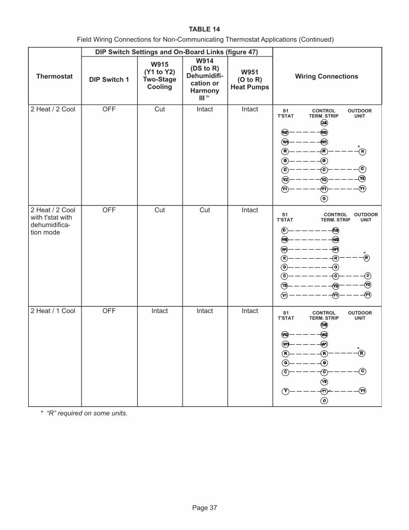
Page 37
TABLE 14 Field Wiring Connections for Non-Communicating Thermostat Applications (Continued)
Thermostat
DIP Switch Settings and On-Board Links (figure 47)
Wiring ConnectionsDIP Switch 1
W915(Y1 to Y2)Two-Stage
Cooling
W914(DS to R)
cation orHarmony
III
W951(O to R)
Heat Pumps
2 Heat / 2 Cool OFF Cut Intact Intact S1T'STAT
CONTROLTERM. STRIP
OUTDOORUNIT
*
2 Heat / 2 Coolwith t'stat with
tion mode
OFF Cut Cut IntactS1
T'STATCONTROL
TERM. STRIPOUTDOOR
UNIT
*
2 Heat / 1 Cool OFF Intact Intact Intact S1T'STAT
CONTROLTERM. STRIP
OUTDOORUNIT
*
* “R” required on some units.

Page 38
TABLE 14 Field Wiring Connections for Non-Communicating Thermostat Applications (Contiued)
Thermostat
DIP Switch Settings and On-Board Links (figure 47)
Wiring ConnectionsDIP SwitchW915
(Y1 to Y2)Two-Stage
Cooling
W914(DS to R)
cation orHarmony
III
W951(O to R)
Heat Pumps
Dual FuelSingle-StageHeat Pump
ComfortSense®
7000 L7742Uthermostat w/
bilitiesCapable of2-stage gasheat control
DIP Switch 1OFF
Intact Intact Cut L7742UT'STAT
CONTROLTERM. STRIP
HEAT PUMP
67M41*
Y
H
L
Y2
D
B
L
Y2
T
Toutdoorsensor
Dual FuelTwo StageHeat Pump
ComfortSense®
7000 L7742Uthermostat w/
bilitiesCapable of2-stage gasheat control
DIP Switch 1OFF
Cut Intact Cut CONTROL TERM.STRIP HEAT PUMP
out blue
67M41*
H
L
Y2
D
B
L
Y2
T
Toutdoorsensor
L7742UT'STAT
* Connect W1 to W1 ONLY if using defrost tempering kit 67M41.NOTE - Do NOT make a wire connection between the room thermostat L terminal and the L terminal of the SLP98integrated control.
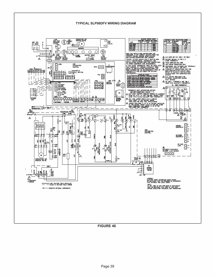
Page 39
FIGURE 46
TYPICAL SLP98DFV WIRING DIAGRAM

Page 40
Integrated Control
THERMOSTAT CONNECTIONS (TB1)
1/4” QUICK CONNECT TERMINALS
RS-BUS LINK (TB82, future use)I+ = DATA HIGH CONNECTIONI - = DATA LOW CONNECTION
RS-BUS OUTDOOR (TB83)R = 24VACI + = DATA HIGH CONNECTIONI - = DATA LOW CONNECTIONC = 24VAXC COMMON
RS-BUS INDOOR (TB84)R = 24VACI + = DATA HIGH CONNECTIONI - = DATA LOW CONNECTIONC = 24VAXC COMMON
+
FLAMESENSE
COMBUSTIONAIR INDUCERCONNECTOR
DIP SWITCHES
OUTDOOR AIRSENSOR
TERMINALS
DISCHARGE AIRSENSOR
TERMINALSW915W951W914
INDOORBLOWER
CONNECTOR
EAC
HUM
LINE VOLTAGETERMINALS
NEUTRALTERMINALS
IGNITORCONNECTOR
7-SEGMENTDIAGNOSTIC LED
DIAGNOSTICPUSH BUTTON
FACTORY TESTHEADER PINS.
FACTORY USE ONLY.
TB83 OUTDOOR
TB84 INDOOR
DS = DEHUMIDIFICATION SIGNALW2 = HEAT DEMAND FROM 2ND STAGE T/STAT
W1 = HEAT DEMAND FROM 1ST STAGE T/STATR = CLASS 2 VOLTAGE TO THERMOSTATG = MANUAL FAN FROM T'STAT
C = THERMOSTAT SIGNAL GROUND CONNECTED TOTRANSFORMER GRD (TR) & CHASIS GROUND (GRD)
Y1 = THERMOSTAT 1ST STAGE COOL SIGNAL
Y2 = THERMOSTAT 2ND STAGE COOL SIGNAL
O = THERMOSTAT SIGNAL TO HEAT PUMPREVERSING VALVE
H = 24V HUMIDIFIER OUTPUT. DO NOT CONNECTTO COMFORTSENSE® THERMOSTAT
L = USE ONLY WITH A COMMUNICATINGTHERMOSTAT AND A NON-COMMUNICATING
OUTDOOR UNIT
DH = DEHUMIDIFICATION OUTPUT COMMUNICATING THERMOSTAT ONLY
HUM = 120 VAC OUTPUT TO HUMIDIFIERXMFR = 120 VAC OUTPUT TO TRANSFORMER
LI = 120 VAC INPUT TO CONTROLCIRC = 120 VAC OUTPUT TO CIRCULATING BLOWEREAC = 120 VAC OUTPUT TO ELECTRICAL AIR CLEANER
NEUTRALS = 120 VAC NEUTRAL
L - use only withcommunicating T'stat and
non-communicating outdoorunit.
W915 Y1 TO Y2W951 R TO OW914 R TO DS
FIGURE 47

Page 41
TABLE 15 Non-Communicating Thermostat Selection Switch Settings
Operation Thermostat Switch 1 Switch 2 Switch 3Variable Capacity Heat (35% to 100%) Two-Stage Off On Off
Three-Stage Heat(35%, 70%, 100%)
Single-Stage On On2nd stage delay OFF = 7 minutes ON = 12 minutes 3rd stage delay
10 minutes fixedTwo-Stage Heat (W1 70%, W2 100%) Two-Stage Off Off Off
NOTE - When the SLP98DFV is used with an icomfort Wi- Fi® thermostat, all indoor blower speed selections and DIP switch settings are made by the communicating thermostat.SLP98DFV units are equipped with an integrated con-trol. This control manages ignition timing, combustion air inducer speed, heating mode fan off delays and indoor blower speeds based on selections made using the con-trol DIP switches and on-board links. The control includes an internal Watchguard feature which automatically resets the ignition control when it has been locked out.NOTE - All DIP switches are factory shipped in the “OFF” position.Heating Operation DIP Switch Settings -- Figure 47 Switch 1 -- Thermostat Selection -- This unit may be used with either a single-stage or two-stage thermostat.\ The thermostat selection is made using a DIP switch which must be properly positioned for the particular appli-cation. The DIP switch is factory-positioned for use with a twostage thermostat. If a single-stage thermostat is to be used, the DIP switch must be repositioned. See table 15.Switch 2 -- Operating Mode with Two-Stage Ther-mostat -- If a two-stage thermostat is used, the furnace can operate in either variable-capacity or conventional twostage mode. When variable-capacity mode is select-ed, the firing rate of the unit is varied to maximize comfort. Conventional two-stage mode is the factory default set-ting. See table 15.Switch 3 -- Second-Stage Heat On Delay -- If a single-stage thermostat is used, the integrated control can be used to energize second-stage heat after either 7 minutes or 12 minutes of first-stage heat operation. See table 15. Switches 4 and 5 -- Blower-Off Delay -- The blower-on delay of 45 seconds is not adjustable.The blower-off delay (time that the blower operates after the heating demand has been satisfied) can be adjusted by moving switches 4 and 5 on the integrated control. The unit is shipped from the factory with a blower-off delay of 90 seconds
The blower off delay affects comfort and is adjustable to satisfy individual applications. Adjust the blower off delay to achieve a supply air temperature between 90° and 110°F at the exact moment that the blower is de-en-ergized. Longer off delay settings provide lower supply air temperatures; shorter settings provide higher supply air temperatures. Table 16 provides the blower off timings that will result from different switch settings.
TABLE 16 Blower-Off Delay Switch Settings
Blower-Off Delay (Seconds) Switch 4 Switch 5
60 Off On90 (factory) Off Off
120 On Off180 On On
Indoor Blower Operation DIP Switch SettingsSwitches 6 and 7 -- Continuous Indoor Fan Opera-tionBlower Speed -- The unit is shipped from the factory with the DIP switches positioned for medium low (2) speed during continuous indoor blower operation. The table be-low provides the continuous blower speeds that will result from different switch settings. Refer to tables beginning on page 37 for corresponding cfm values.
TABLE 17 Continuous Indoor Blower Operation -- Blower Speeds
Speed Switch 6 Switch 61 - Low (28%)* Off On
2 - Medium Low (38%)* Factory
Off Off
3 - Medium High (70%)* On Offf4 - High (100%)* On On
* Percentage of high speed cooling

Page 42
Switches 8 and 9 -- Cooling Mode Blower Speed -- The unit is shipped from the factory with the DIP switches po-sitioned for high speed (4) indoor blower motor operation during the cooling mode. The table below provides the cooling mode blower speeds that will result from different switch settings. Refer to tables beginning on page 44 for corresponding cfm values.
TABLE 18 Cooling Mode Blower Speeds
Speed Switch 8 Switch 91 - Low On On
2 - Medium Low Off On3 - Medium High On Off4 - High Factory Off Off
Switches 10 and 11 -- Cooling Mode Blower Speed Ad-justment -- The unit is shipped from the factory with the DIP switches positioned for NORMAL (no) adjustment. The DIP switches may be positioned to adjust the blower speed by +10% or -10% to better suit the application. Ta-ble 19 provides blower speed adjustments that will result from different switch settings. Refer to tables beginning on page 44 for corresponding cfm values.With switches 10 and 11 set to ON, motor will bypass ramping profiles and all delays and will immediately run at selected COOLING speed upon a call for cool. LED will continue to operate as normal. This mode is used to check motor operation.
TABLE 19 Cooling Mode Blower Speed Adjustment
Adjustment Switch 10 Switch 11+10% (approx.) On Off
Default Cool CFM Off Off- 10% (approx.) Off On
Motor Test On On Switches 12 and 13 -- Cooling Mode Blower Speed Ramp-ing -- Blower speed ramping may be used to enhance de-humidification performance. The switches are factory set at option A which has the greatest effect on blower motor performance. Table 20 provides the cooling mode blower speed ramping options that will result from different switch settings. The cooling mode blower speed ramping options are detailed below.NOTE - The off portion of the selected ramp profile only applies during heat pump operation in dual fuel applica-tions.
TABLE 20 Cooling Mode Blower Speed Ramping
Ramping Option Switch 12 Switch 13 A (factory) On Off
B Off OffC Off OnD On On
Ramping Option A (Factory Selection)
• Motor runs at 50% for 30 seconds.• Motor then runs at 82% for approximately 7-1/2 min-
utes.• If demand has not been satisfied after 7-1/2 minutes,• motor runs at 100% until demand is satisfied.• Once demand is met, motor runs at 50% for 30 seconds
then ramps down to stop.
OFFOFF1/2 MIN50% CFM
COOLING DEMAND
7 1/2 MIN82% CFM
100% CFM
1/2 MIN50% CFM
Ramping Option B
• Motor runs at 82% for approximately 7-1/2 minutes. If demand has not been satisfied after 7-1/2 minutes, mo-tor runs at 100% until demand is satisfied.
• Once demand is met, motor ramps down to stop.
OFFOFF 82%CFM100% CFM
COOLING DEMAND
7 1/2 MIN
Ramping Option C
• Motor runs at 100% until demand is satisfied.• Once demand is met, motor runs at 100% for 45 sec-
onds then ramps down to stop.
OFFOFF100% CFM 100% CFM
COOLING DEMAND45 SEC.
.Ramping Option D
• Motor runs at 100% until demand is satisfied.• Once demand is met, motor ramps down to stop.
OFFOFF100% CFM
COOLING DEMAND

Page 43
Switches 14 through 19 -- Heating Mode Blower Speed-- These switches are factory set at the OFF position which provides 100 % of normal speed during HIGH HEAT demand, 70% of normal speed during MID-RANGE HEAT demand and 35% of normal speed during LOW HEAT demand. Switches 14, 15 and 16 are used to adjust the LOW HEAT blower motor speed. Switches 17, 18 and 19 are used to adjust the HIGH HEAT blower motor speed. Table 21 provides the heating mode blower speeds that will result from different switch settings. Refer to tables beginning on page 44 for corresponding cfm values.
TABLE 21 Low Heat Blower Speeds
Thermostat Demand
Blower Speed
Adjustments
DIP Switch Settings
Low Heat (R to W1)
14 15 16+ 15% On Off On+ 7.5% On Off OffNormal Off Off Off- 7.5% On On Off- 15% On On On
TABLE 22 High Heat Blower Speeds
Thermostat Demand Blower Speed
AdjustmentsDIP Switch Settings
High Heat (R to W1 &
W2)
17 18 19+ 15% On Off On+ 7.5% On Off OffNormal Off Off Off- 7.5% On On Off- 15% On On On
On-Board Links
On-Board links must be clipped (when applicable) before unit is placed into operation with a non-communicating thermostat.On-Board Link W914 (DS to R) -- Figure 47On-board link W914 is a clippable connection between terminals DS and R on the integrated control. W914 must be cut when the furnace is installed with either the Harmo-ny III zone control or a thermostat which features humidity control. If the link is left intact the PMW signal from the Harmony III control will be blocked and also lead to control damage. Refer to table 24 for operation sequence in appli-cations including SLP98DFV, a thermostat which featureshumidity control and a single-speed outdoor unit. Table 25 gives the operation sequence in applications with a two-speed outdoor unit.On-Board Link W951 (R to O) -- Figure 47On-board link W951 is a clippable connection between terminals R and O on the integrated control. W951 must be cut when the furnace is installed in applications which include a heat pump unit and a thermostat which features dual fuel use. If the link is left intact, terminal “O” will re-main energized eliminating the HEAT MODE in the heat pump.
On-Board Link W915 (Y1 to Y2) -- Figure 47
On-board link W915 is a clippable connection between terminals Y1 and Y2 on the integrated control. W915 must be cut if two-stage cooling will be used. If the link is not cut the outdoor unit will operate in second-stage cooling only.Diagnostic LED -- Figure 47
The seven-segment diagnostic LED displays operating status, target airflow, error codes and other information. The table on Page 57 lists diagnostic LED codes.Diagnostic Push Button -- Figure 47
The diagnostic push button is located adjacent to the sev-en-segment diagnostic LED. This button is used to enable the Error Code Recall mode and the Field Test mode. Press the button and hold it to cycle through a menu of options. Every five seconds a new menu item will be dis-played. When the button is released, the displayed item will be selected. Once all items in the menu have been displayed, the menu resumes from the beginning until the button is released.Error Code Recall Mode
Select ”E” from the menu to access the most recent ten error codes. Select “c” from the Error Code Recall menu to clear all error codes. Button must be pressed a second time while “c” is flashing to confirm command to delete codes. Press the button until a solid “≡” is displayed to exit the Error Code Recall mode.Field Test Mode
Use the diagnostic push button to scroll through the menu as described above. Release the button when the LED flashes “-” to select the Field Test mode. While in the Field Test mode the technician can:• Initiate furnace ignition and move to and hold low-fire
rate by applying a R to W1 jumper.• Initiate furnace ignition sequence and move to and hold
high-fire rate by applying a jumper from R to W1 nd W2.• Initiate furnace ignition sequence and move to and hold
mid-fire rate by applying a jumper to R and W2.• Apply then remove the jumper from R to W1 and W2 to
change the firing rate from low fire to mid fire and high fire.
• A vent calibration sequence can be initiated even if a thermostat signal is not present. Press and hold the push button until a solid “C” is displayed. Release the button and calibration will begin. The furnace will per-form the high-fire and low-fire pressure switch calibra-tions and display “CAL”. After calibration, the LED will return to the flashing “-” display.
During Field Test mode operation, all safety switches are still in the circuit (they are not by-passed) and indoor blow-er performance and timings will match DIP switch selec-tions. Current furnace firing rate, indoor blower CFM and flame signal will be displayed. To exit the Field Test mode, press and hold the button. The menu will resume from the beginning. Also, cycle the main power to exit the Field Test mode. The integrated control will automatically exit the Field Test mode after 45 minutes of operation.

Page 44
BLOWER DATASLP98DF070XV36B BLOWER PERFORMANCE (less filter)HEATING BLOWER PERFORMANCE - 0 through 0.8 in. w.g. External Static Pressure Range
Heating Adjust CFM SelectionsHeating Input Range and Blower Volume - CFM
35% 40% 50% 60% 70% 80% 90% 100%Increase (+15%) Heat CFM 495 543 639 735 830 926 1022 1118Increase (+7.5%) Heat CFM 473 516 604 691 778 866 953 1041Default Heat CFM 450 489 568 647 726 805 884 963Decrease (-7.5% ) Heat CFM 430 467 540 614 687 761 834 908Decrease (-15% ) Heat CFM 410 444 512 580 649 717 785 853
COOLING BLOWER PERFORMANCE - 0 through 1.0 in. w.g. External Static Pressure RangeCooling Adjust CFM
SelectionsBlower Speed Selections
First Stage Cool Speed - cfm Second Stage Cool Speed - cfmLow Medium-
Low Medium
HighHigh
(Default)Low Medium-
Low Medium
HighHigh
(Default)Increase (+10%) Cool CFM 625 785 890 995 910 1075 1230 1365Default Cool CFM 575 710 830 890 845 960 1125 1265Decrease (-10%) Cool CFM 520 615 710 820 755 885 985 1150
BLOWER DATASLP98DF090XV36C BLOWER PERFORMANCE (less filter)HEATING BLOWER PERFORMANCE - 0 through 0.8 in. w.g. External Static Pressure Range
Heating Adjust CFM SelectionsHeating Input Range and Blower Volume - CFM
35% 40% 50% 60% 70% 80% 90% 100%Increase (+15%) Heat CFM 710 756 848 940 1033 1125 1217 1309Increase (+7.5%) Heat CFM 670 713 799 885 971 1057 1143 1230Default Heat CFM 629 669 749 829 910 990 1070 1150Decrease (-7.5% ) Heat CFM 559 599 681 763 845 927 1009 1091Decrease (-15% ) Heat CFM 488 530 614 697 781 865 948 1032
COOLING BLOWER PERFORMANCE - 0 through 1.0 in. w.g. External Static Pressure RangeCooling Adjust CFM
SelectionsBlower Speed Selections
First Stage Cool Speed - cfm Second Stage Cool Speed - cfmLow Medium-
Low Medium
HighHigh
(Default)Low Medium-
Low Medium
HighHigh
(Default)Increase (+10%) Cool CFM 610 770 900 1035 920 1080 1215 1385Default Cool CFM 545 690 805 920 835 1000 1135 1255Decrease (-10%) Cool CFM 465 620 720 810 750 890 1025 1145
The effect of static pressure is included in air volumes shown. The following control configurations are available. See Installation Instructions for details and DIP switch settings.Heat Modes Available (Heating Blower Performance Table): Single-stage thermostat: - 35%, 70%, 100% input (three-stage) with time delays in-between Two-stage thermostat: - Variable Rate Capacity Mode - furnace automatically adjusts firing rate based on first- and second-stage cycle times. - W1 demand at 70% input, W2 demand at 100% input. No delay between stages.Cool Mode Available (Cooling Blower Performance Table): First stage COOL (two-stage air conditioning units only) is approximately 70% of the same second stage COOL speed position. Continuous Fan speeds are approximately 28%, 38%, 70% and 100% (DIP switch selectable) of the same second-stage COOL speed position minimum 250 cfm.Lennox iHarmony® Zoning System Applications - Minimum blower speed is 250 cfm.

Page 45
BLOWER DATASLP98DF090XV48C BLOWER PERFORMANCE (less filter)HEATING BLOWER PERFORMANCE - 0 through 0.8 in. w.g. External Static Pressure Range
Heating Adjust CFM SelectionsHeating Input Range and Blower Volume - CFM
35% 40% 50% 60% 70% 80% 90% 100%Increase (+15%) Heat CFM 723 790 925 1060 1195 1329 1464 1599Increase (+7.5%) Heat CFM 690 752 878 1004 1129 1255 1381 1507Default Heat CFM 656 714 831 948 1064 1181 1297 1414Decrease (-7.5% ) Heat CFM 601 654 761 867 974 1081 1188 1295Decrease (-15% ) Heat CFM 545 593 690 787 884 981 1078 1175
COOLING BLOWER PERFORMANCE - 0 through 1.0 in. w.g. External Static Pressure RangeCooling Adjust CFM
SelectionsBlower Speed Selections
First Stage Cool Speed - cfm Second Stage Cool Speed - cfmLow Medium-
Low Medium
HighHigh
(Default)Low Medium-
Low Medium
HighHigh
(Default)Increase (+10%) Cool CFM 775 940 1100 1255 1120 1340 1535 1745Default Cool CFM 690 875 975 1135 1000 1220 1425 1625Decrease (-10%) Cool CFM 635 755 915 1025 920 1100 1270 1470
The effect of static pressure is included in air volumes shown. The following control configurations are available. See Installation Instructions for details and DIP switch settings.Heat Modes Available (Heating Blower Performance Table): Single-stage thermostat: - 35%, 70%, 100% input (three-stage) with time delays in-between Two-stage thermostat: - Variable Rate Capacity Mode - furnace automatically adjusts firing rate based on first- and second-stage cycle times. - W1 demand at 70% input, W2 demand at 100% input. No delay between stages.Cool Mode Available (Cooling Blower Performance Table): First stage COOL (two-stage air conditioning units only) is approximately 70% of the same second stage COOL speed position. Continuous Fan speeds are approximately 28%, 38%, 70% and 100% (DIP switch selectable) of the same second-stage COOL speed position minimum 250 cfm.
Lennox iHarmony® Zoning System Applications - Minimum blower speed is 380 cfm.

Page 46
BLOWER DATASLP98DF090XV60C BLOWER PERFORMANCE (less filter)HEATING BLOWER PERFORMANCE - 0 through 0.8 in. w.g. External Static Pressure Range
Heating Adjust CFM SelectionsHeating Input Range and Blower Volume - CFM
35% 40% 50% 60% 70% 80% 90% 100%Increase (+15%) Heat CFM 653 728 877 1027 1176 1326 1475 1625Increase (+7.5%) Heat CFM 603 673 813 953 1092 1232 1372 1512Default Heat CFM 553 618 748 878 1009 1139 1269 1399Decrease (-7.5% ) Heat CFM 510 570 690 811 931 1051 1171 1292Decrease (-15% ) Heat CFM 467 522 632 743 853 963 1074 1184
COOLING BLOWER PERFORMANCE - 0 through 1.0 in. w.g. External Static Pressure RangeCooling Adjust CFM
SelectionsBlower Speed Selections
First Stage Cool Speed - cfm Second Stage Cool Speed - cfmLow Medium-
Low Medium
HighHigh
(Default)Low Medium-
Low Medium
HighHigh
(Default)Increase (+10%) Cool CFM 1110 1265 1395 1600 1600 1750 1965 2130Default Cool CFM 1000 1145 1275 1445 1445 1625 1805 1975Decrease (-10%) Cool CFM 885 1060 1145 1265 1265 1445 1645 1805
BLOWER DATASLP98DF110XV60C BLOWER PERFORMANCE (less filter)HEATING BLOWER PERFORMANCE - 0 through 0.8 in. w.g. External Static Pressure Range
Heating Adjust CFM SelectionsHeating Input Range and Blower Volume - CFM
35% 40% 50% 60% 70% 80% 90% 100%Increase (+15%) Heat CFM 811 906 1096 1286 1475 1665 1855 2045Increase (+7.5%) Heat CFM 744 835 1017 1199 1380 1562 1744 1926Default Heat CFM 677 764 938 1112 1285 1459 1633 1807Decrease (-7.5% ) Heat CFM 626 707 869 1031 1193 1355 1517 1679Decrease (-15% ) Heat CFM 575 650 800 950 1101 1251 1401 1551
COOLING BLOWER PERFORMANCE - 0 through 1.0 in. w.g. External Static Pressure RangeCooling Adjust CFM
SelectionsBlower Speed Selections
First Stage Cool Speed - cfm Second Stage Cool Speed - cfmLow Medium-
Low Medium
HighHigh
(Default)Low Medium-
Low Medium
HighHigh
(Default)Increase (+10%) Cool CFM 1090 1260 1395 1580 1580 1790 1990 2180Default Cool CFM 965 1125 1285 1440 1440 1625 1845 2000Decrease (-10%) Cool CFM 860 1030 1125 1270 1270 1470 1655 1845
The effect of static pressure is included in air volumes shown. The following control configurations are available. See Installation Instructions for details and DIP switch settings.Heat Modes Available (Heating Blower Performance Table): Single-stage thermostat: - 35%, 70%, 100% input (three-stage) with time delays in-between Two-stage thermostat: - Variable Rate Capacity Mode - furnace automatically adjusts firing rate based on first- and second-stage cycle times. - W1 demand at 70% input, W2 demand at 100% input. No delay between stages.Cool Mode Available (Cooling Blower Performance Table): First stage COOL (two-stage air conditioning units only) is approximately 70% of the same second stage COOL speed position. Continuous Fan speeds are approximately 28%, 38%, 70% and 100% (DIP switch selectable) of the same second-stage COOL speed position minimum 250 cfm.Lennox iHarmony® Zoning System Applications - Minimum blower speed is 450 cfm.

Page 47
TABLE 23 COOLING OPERATING SEQUENCE
SLP98DFV and Single-Stage Outdoor UnitOPERATING SEQUENCE SYSTEM DEMAND SYSTEM RESPONSE
SystemCondition
StepThermostat Demand Relative Humidity
CompressorBlower CFM (cool)
Comments1st stage O G Status D*
NO CALL FOR DEHUMIDIFICATION
Normal Operation 1 On On On Acceptable 24 VAC High 100%
Compressor and indoor blower follow thermostat demand
BASIC MODE (only active on a Y1 thermostat demand)
Normal Operation 1 On On On Acceptable 24 VAC High 100% Thermostat energizes Y1
and de-energizes D on a call for de-humidificationDehumidification
call 2 On On On Demand 0 VAC High 70%
PRECISION MODE (operates independent of a Y1 demand)
Normal Operation 1 On On On Acceptable 24 VAC High 100% Dehumidification mode
begins when humidity is greater than set pointDehumidification
Call 2 On On On Demand 0 VAC High 70%
Dehumidification Call Only 1 On On On Demand 0 VAC High 70% Thermostat will keep
outdoor unit energized after cooling temperature setpoint has been reached in order to maintain room humidity
setpoint.
On-board links at indoor unit with a single-stage outdoor unit:With Condensing unit - Cut W914 (R to DS) on SureLight® control;With Heat Pump - Cut W914 (R to DS) & W951 (R to O)on SureLight® control.*ComfortSense® 7500 thermostat only

Page 48
TABLE 24 OPERATING SEQUENCE
SLP98DFV and Two-Speed Outdoor UnitOPERATING SEQUENCE SYSTEM DEMAND SYSTEM RESPONSE
SystemCondition
StepThermostat Demand Relative Humidity
CompressorBlower CFM (cool)
Comments1 s t stage
2ndstage
O G Status D*
NO CALL FOR DEHUMIDIFICATIONNormal Operation
Y1 1 On On On Acceptable 24 VAC Low 70%
Compressor and indoor blower follow thermostat demandNormal Operation
Y2 2 On On On On Acceptable 24 VAC High 100%
ROOM THERMOSTAT CALLS FOR FIRST STAGE COOLINGBASIC MODE (only active on a Y1 thermostat demand)
Normal Operation 1 On On On Acceptable 24 VAC Low 70% Thermostat energizes 2nd stage
and de-energizes D on a call for dehumidificationDehumidification
call 2 On On On On Demand 0 VAC High 70%
PRECISION MODE (operates independent of a Y1 demand)
Normal Operation 1 On On On Acceptable 24 VAC Low 70% Dehumidification mode begins
when humidity is greater than set pointDehumidification
Call 2 On On On On Demand 0 VAC High 70%
Dehumidification Call Only 1 On On On On Demand 0
VAC High 70%
Thermostat will keep outdoor unit energized after cooling temperature setpoint has been reached in order to maintain room humidity setpoint.*
ROOM THERMOSTAT CALLS FOR FIRST AND SECOND STAGE COOLINGBASIC MODE (only active on a Y1 thermostat demand)
Normal Operation 1 On On On On Acceptable 24 VAC High 100% Thermostat energizes 2nd stage
and de-energizes D on a call for dehumidificationDehumidification
Call 2 On On On On Demand 0 VAC High 70%
PRECISION MODE (operates independent of a Y1 thermostat demand)
Normal Operation 1 On On On Acceptable 24 VAC Low 70% Dehumidification mode begins
when humidity is greater than set pointDehumidification
Call 2 On On On On Demand 0 VAC High 70%
Dehumidification Call ONLY 1 On On On On Demand 0
VAC High 70%Thermostat will keep outdoor unit energized after cooling temperature set-point has been reached in order to maintain room humidity set-point.
On-board links at indoor unit with a two-stage outdoor unit:Cut factory link from Y1 to Y2 or cut W915 (Y1 to Y2) on SureLight® integrated control.With Condensing unit - Cut W914 (R to DS) on SureLight® integrated control;With Heat Pump - Cut W914 (R to DS) & W951 (R to O) on SureLight® integrated control.*ComfortSense® 7500 thermostat only

Page 49
Unit Start-UpFOR YOUR SAFETY READ BEFORE OPERATING
WARNINGDo not use this furnace if any part has been underwater. A flood-damaged furnace is extremely dangerous. Attempts to use the furnace can result in fire or explosion. Immediately call a qualified service technician to inspect the furnace and to replace all gas controls, control system parts, and electrical parts that have been wet or to replace the furnace, if deemed necessary.
WARNINGDanger of explosion. Can cause injury or product or property damage. Should the gas supply fail to shut off or if overheating occurs, shut off the gas valve to the furnace before shutting off the electrical supply.
CAUTIONBefore attempting to perform any service or maintenance, turn the electrical power to unit OFF at disconnect switch.
WARNINGDuring blower operation, the ECM motor emits energy that may interfere with pacemaker operation. Interference is reduced by both the sheet metal cabinet and distance.
Priming Condensate Trap
The condensate trap should be primed with water prior to start-up to ensure proper condensate drainage. Either pour 10 fl. oz. (300 ml) of water into the trap, or follow these steps to prime the trap:
1 - Follow the lighting instructions to place the unit into operation.
2 - Set the thermostat to initiate a heating demand.3 - Allow the burners to fire for approximately 3 minutes.4 - Adjust the thermostat to deactivate the heating
demand.5 - Wait for the combustion air inducer to stop. Set the
thermostat to initiate a heating demand and again allow the burners to fire for approximately 3 minutes.
6 - Adjust the thermostat to deactivate the heating demand and again wait for the combustion air inducer to stop. At this point, the trap should be primed with sufficient water to ensure proper condensate drain operation.
BEFORE BEFORE PLACING THE UNIT INTO OPERA-TION, smell all around the furnace area for gas. Be sure to smell next to the floor because some gas is heavier than air and will settle on the floor. The gas valve on the SLP98DFV is equipped with a gas control switch. Use only your hand to move the control switch. Never use tools. If the switch will not move by hand, do not try to repair it. Force or attempted repair may result in a fire or explosion.Placing the furnace into operation:
SLP98DFV units are equipped with an automatic ignition system. Do not attempt to manually light burners on this furnace. Each time the thermostat calls for heat, the burn-ers will automatically light. The ignitor does not get hot when there is no call for heat on units with this ignition system.
WARNINGIf you do not follow these instructions exactly, a fire or explosion may result causing property damage, personal injury or death.
Gas Valve Operation (Figure 48)1 - STOP! Read the safety information at the beginning
of this section.2 - Set the thermostat to the lowest setting.3 - Turn off all electrical power to the unit.4 - This furnace is equipped with an ignition device
which automatically lights the burners. Do not try to light the burners by hand.
5 - Remove the access panel.6 - Move the gas valve switch to the OFF position. See
figure 48.7 - Wait five minutes to clear out any gas. If you then
smell gas, STOP! Immediately call the gas supplier from a neighbor’s phone. Follow the gas supplier’s instructions. If you do not smell gas go to next step.
8 - Move gas valve switch to the ON position. See figure 48. Do not force.
GAS VALVENEGATIVE AIRPRESSURE PORT
POSITIVE AIRPRESSURE PORT
MANIFOLDPRESSURE TAP
INLET OUTLET
SUPPLYPRESSURE
TAPGAS VALVE SHOWN IN THE ON POSITION
FIGURE 48
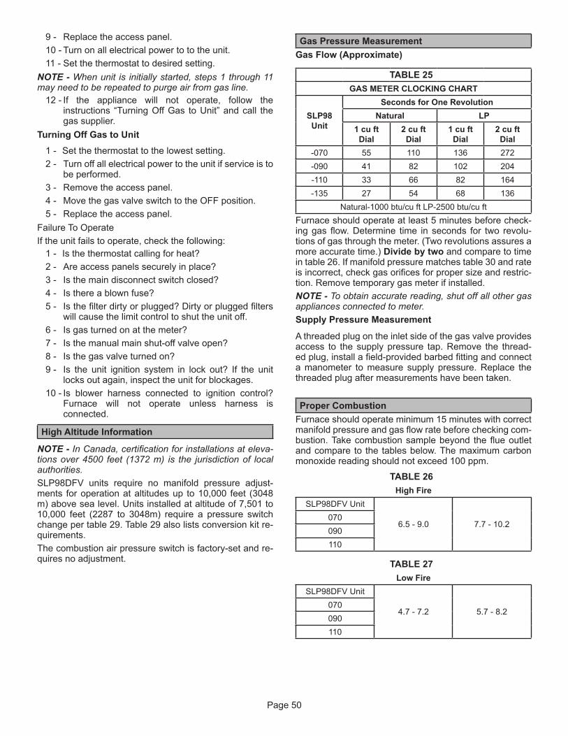
Page 50
9 - Replace the access panel.10 - Turn on all electrical power to to the unit.11 - Set the thermostat to desired setting.
NOTE - When unit is initially started, steps 1 through 11 may need to be repeated to purge air from gas line.
12 - If the appliance will not operate, follow the instructions “Turning Off Gas to Unit” and call the gas supplier.
Turning Off Gas to Unit1 - Set the thermostat to the lowest setting.2 - Turn off all electrical power to the unit if service is to
be performed.3 - Remove the access panel.4 - Move the gas valve switch to the OFF position.5 - Replace the access panel.
Failure To OperateIf the unit fails to operate, check the following:
1 - Is the thermostat calling for heat?2 - Are access panels securely in place?3 - Is the main disconnect switch closed?4 - Is there a blown fuse?5 - Is the filter dirty or plugged? Dirty or plugged filters
will cause the limit control to shut the unit off.6 - Is gas turned on at the meter?7 - Is the manual main shut-off valve open?8 - Is the gas valve turned on?9 - Is the unit ignition system in lock out? If the unit
locks out again, inspect the unit for blockages.10 - Is blower harness connected to ignition control?
Furnace will not operate unless harness is connected.
High Altitude Information
NOTE - In Canada, certification for installations at eleva-tions over 4500 feet (1372 m) is the jurisdiction of local authorities.SLP98DFV units require no manifold pressure adjust-ments for operation at altitudes up to 10,000 feet (3048 m) above sea level. Units installed at altitude of 7,501 to 10,000 feet (2287 to 3048m) require a pressure switch change per table 29. Table 29 also lists conversion kit re-quirements.The combustion air pressure switch is factory-set and re-quires no adjustment.
Gas Pressure MeasurementGas Flow (Approximate)
TABLE 25 GAS METER CLOCKING CHART
SLP98 Unit
Seconds for One RevolutionNatural LP
1 cu ft Dial
2 cu ft Dial
1 cu ft Dial
2 cu ft Dial
-070 55 110 136 272-090 41 82 102 204-110 33 66 82 164-135 27 54 68 136
Natural-1000 btu/cu ft LP-2500 btu/cu ftFurnace should operate at least 5 minutes before check-ing gas flow. Determine time in seconds for two revolu-tions of gas through the meter. (Two revolutions assures a more accurate time.) Divide by two and compare to time in table 26. If manifold pressure matches table 30 and rate is incorrect, check gas orifices for proper size and restric-tion. Remove temporary gas meter if installed.NOTE - To obtain accurate reading, shut off all other gas appliances connected to meter.Supply Pressure Measurement
A threaded plug on the inlet side of the gas valve provides access to the supply pressure tap. Remove the thread-ed plug, install a field-provided barbed fitting and connect a manometer to measure supply pressure. Replace the threaded plug after measurements have been taken. Proper Combustion
Furnace should operate minimum 15 minutes with correct manifold pressure and gas flow rate before checking com-bustion. Take combustion sample beyond the flue outlet and compare to the tables below. The maximum carbon monoxide reading should not exceed 100 ppm.
TABLE 26
High FireSLP98DFV Unit
6.5 - 9.0 7.7 - 10.2070090110
TABLE 27
Low FireSLP98DFV Unit
4.7 - 7.2 5.7 - 8.2070090110

Page 51
Manifold Pressure Measurement (Figure 49)
To correctly measure manifold pressure, the differential pressure between the positive gas manifold and the neg-ative burner box must be considered. Use pressure test adapter kit (available as Lennox part 10L34) to assist in measurement.
1 - Remove the threaded plug from the outlet side of the gas valve and install a field-provided barbed fitting. Connect measuring device “+” connection to barbed fitting to measure manifold pressure.
2 - Tee into the gas valve regulator vent hose and connect measuring device “-” connection.
3 - Start unit on low heat (35% rate) and allow 5 minutes for unit to reach steady state.
4 - While waiting for the unit to stabilize, notice the flame. Flame should be stable and should not lift from burner. Natural gas should burn blue.
5 - After allowing unit to stabilize for 5 minutes, record manifold pressure and compare to value given in table 30.
6 - Repeat steps 3, 4 and 5 on high heat.7 - Shut unit off and remove manometer as soon as
an accurate reading has been obtained. Take care to remove barbed fitting and replace threaded plug.
8 - Start unit and perform leak check. Seal leaks if found.
TABLE 28 Conversion Kit Requirements
Model Input Size
LP/Propane High Altitude Pressure Switch
0 - 10,000 ft (0 - 3048m)
0 - 7500 ft (0 - 2286m)
7501 ft - 10,000 ft(287 - 3048m)
07065W77 Not
Required 14T67090110
Operating Pressure Signal (Delta P) Measurement (Figure 50)
Operating pressure signal can be taken while the manifold pressure pressure check is taken (using two measuring devices). Or, taken after the manifold pressure measure-ment is complete.
1 - Tee into the negative line between the gas valve and pressure switch and connect to measuring device negative “-”.
2 - Tee into the positive line between the gas valve and pressure switch and connect to measuring device positive “+”.
3 - Start unit on low heat (35% rate) and allow 5 minutes for unit to reach steady state.
4 - After allowing unit to stabilize for 5 minutes, record operating pressure signal and compare to value given in table 30.
5 - Repeat steps 3 on 4 high heat.
WARNINGDo not attempt to make adjustments to the gas valve.
.
TABLE 29 Manifold and Operating Signal Pressures in inches 0 - 7500 ft (0 - 2286 m)
SLP98 Firing Rate
Manifold Pressure Natural Gas Manifold Pressure LP/Propane Operating Pressure Signal (Delta P)Min Max Min Max Min Max
Low 0.4 0.95 1.2 2.8 0.20 0.40High 3.0 3.8 9.1 10.5 0.95 1.25
NOTE - A natural to LP/propane gas changeover kit is necessary to convert this unit. Refer to the changeover kit instal-lation instruction for the conversion procedure.NOTE - The values given in table are measurements only. The gas valve should NOT be adjusted.

Page 52
Field Installed
Gas Valve
MANIFOLD PRESSURE MEASUREMENT
Figure 49
Negative PortPositive Port
Gas Valve
Measuring Device
Field Installed
Operating Signal (Delta P) Measurement
Black Tubing +
Red and Black Tubing -
Figure 50

Page 53
Other Unit AdjustmentsPrimary Limit
The primary limit is located on the heating compartment vestibule panel. This limit is factory set and require no ad-justment.Flame Rollout Switches (Two)
These manually reset switches are located on the burner box.Pressure Switches (Two)
The pressure switches are located in the heating com-partment on the combustion air inducer. These switches check for proper combustion air inducer operation before allowing ignition trial. The switches are factory-set and re-quire no adjustment. Pressure switch tubing installation is critical for safe operation. See figure 51.
PRESSURE SWITCH TUBING INSTALLATION
1
2
34
Gas Valve
Cold EndHeader Box
High-FirePressureSwitch
Low-FirePressureSwitch
1 - Black tubing from front port on low-fire pressure switch topositive port on the gas valve.
2 - Red and black tubing from rear port on low-fire pressureswitch to the negative port on the gas valve.
3 - Red and black tubing from front port on high-fire pressureswitch to negative port on cold end header box.
4 - Black tubing from rear port on high-fire pressure switch topositive port on cold end header box.
FIGURE 51
Temperature RiseAfter the furnace has been started and supply and return air temperatures have been allowed to stabilize, check the temperature rise with the unit operating at 100 percent fir-ing rate. If necessary, adjust the blower speed to maintain the temperature rise within the range shown on the unit nameplate. Increase the blower speed to decrease the temperature. Decrease the blower speed to increase the temperature rise. Failure to adjust the temperature rise may cause erratic limit operation.Electrical
1 - Check all wiring for loose connections.2 - Check for the correct voltage at the furnace (furnace
operating).Correct voltage is 120VAC + 10%.3 - Check amp-draw on the blower motor with
innerlower panel in place.Motor Nameplate__________Actual__________
Electronic Ignition
The integrated control has an added feature of an inter-nalWatchguard control. The feature serves as an auto-matic reset device for ignition control lockout caused by ignition failure. This type of lockout is usually due to low gas line pressure. After one hour of continuous thermostat demand for heat, the Watchguard will break and remake thermostat demand to the furnace and automatically reset the control to begin the ignition sequence.Exhaust and Air Intake Pipe
1 - Check exhaust and air intake connections for tightness and to make sure there is no blockage.
2 - Are pressure switches closed? Obstructed exhaust pipe will cause unit to shut off at pressure switches. Check termination for blockages.
3 - Reset manual flame rollout switches on burner box cover.
Heating Sequence of OperationThe integrated control initiates a pressure switch calibra-tion at the initial unit start-up on a call for heat. The ignition control will also initiate a calibration any time main power is turned off and back on and a heating demand is pres-ent . Additional calibrations may be initiated by the ser-vice technician during field test sequence. The following heating sequence of operation assumes completion of a successful calibration.NOTE - The thermostat selection DIP switch on the inte-grated control is factory-set in the “TWO-STAGE” position.
Applications Using a Two-Stage ThermostatA - Heating Sequence -- Control Thermostat SelectionDIP switch in “Two-Stage” Position (Factory Setting)
1 - On a call for heat, thermostat first-stage contacts close sending a signal to the integrated control. The integrated control runs a self-diagnostic program and checks high temperature limit switches for normally closed contacts and pressure switches for normally open contacts. The combustion air inducer is energized at ignition speed, which is approximately the same as the inducer speed at 70 percent firing rate.
Page 54
2 - Once the control receives a signal that the low-fire pressure switch has closed, the combustion air inducer begins a 15-second pre-purge in the ignition speed.
3 - After the pre-purge is complete, a 20-second initial ignitor warm-up period begins. The combustion air inducer continues to operate at the ignition speed.
4 - After the 20-second warm-up period has ended, the gas valve is energized and ignition occurs. At the same time, the control module sends a signal to begin an indoor blower 45-second ON delay. When the delay ends, the indoor blower motor is energized at a speed that matches the firing rate. After the 10-second ignition stabilization delay expires, the inducer speed is adjusted to the appropriate target rate. The inducer will remain at the 70 percent speed as long as the thermostat has a first-stage heating demand.
5 - second-stage heat is required, the thermostat second- stage heat contacts close and send a signal to the integrated control. The integrated control initiates a 30-second second-stage recognition delay.
6 - At the end of the recognition delay and for all subsequent calls for second-stage heat, the integrated control energizes the combustion air inducer at high speed. The control also checks the high-fire pressure switch to make sure it is closed. As the inducer speed is increased to high, the indoor blower motor is adjusted to a speed which is appropriate for secondstage heat.
7 - When the demand for high-fire (second stage) heat is satisfied, the gas valve is de-energized and the fieldselected indoor blower off delay begins. The combustion air inducer begins a 20-second post-purge period.
8 - When the combustion air post-purge period is complete, the inducer is de-energized. The indoor blower is de-energized at the end of the off delay.
Applications Using a Two-Stage ThermostatB - Heating Sequence -- Control Thermostat SelectionDIP switch in “Variable Capacity” Position
1 - On a call for heat, thermostat first-stage contacts close sending a signal to the integrated control. The integrated control runs a self-diagnostic program and checks high temperature limit switches for normally closed contacts and pressure switches for normally open contacts. The combustion air inducer is energized at ignition speed, which is approximately the same as the inducer speed at 70 percent firing rate.
2 - Once the control receives a signal that the low-fire pressure switch has closed, the combustion air inducer begins a 15-second pre-purge in low speed.
3 - After the pre-purge is complete, a 20-second initial ignitor warm-up period begins. The combustion air inducer continues to operate at the ignition speed.
4 - After the 20-second warm-up period has ended, the gas valve is energized and ignition occurs.At the same time, the control module begins an indoor blower 45-second ON delay. When the delay ends, the indoor blower motor is energized at a speed that matches the firing rate. After the 10-second ignition stabilization delay expires, the inducer speed is adjusted to the appropriate target rate. If the furnace is operating in the initial heating cycle after power-up, the initial firing rate will be approximately 35 percent. The firing rate on subsequent cycles will be automatically adjusted by the integrated control based on thermostat cycles. The firing rate will vary and will range from 35 percent to 90 percent. The furnace will continue this operation as long as the thermostat has a first-stage heating demand.
5 - If second-stage heat is required, the thermostat second- stage heat contacts close and send a signal to the integrated control. The integrated control either increases the firing rate to 70 percent (if the current rate is at or below 60 percent) or increases the firing rate by 10 percent (if the current rate is above 60 percent). If the call for heat continues 5 minutes beyond this initial upstage, the rate will be increased by 10 percent every 5 minutes until the call for heat is satisfied or the furnace reaches 100 percent rate. As the firing rate increases, the indoor blower motor is adjusted to a speed which is appropriate for the target rate.
6 - If second-stage heat demand is satisfied, but first stage is still present, the furnace will continue to operate at the present firing rate until the heat cycle ends.
7 - When the demand for first- and second-stage heat is satisfied, the gas valve is de-energized and the fieldselected indoor blower off delay begins. The combustion air inducer begins a 20-second post-purge period.
8 - When the combustion air post-purge period is complete, the inducer is de-energized. The indoor blower is de-energized at the end of the off delay.
Applications Using A Single-Stage ThermostatC - Heating Sequence -- Control Thermostat SelectionDIP switch in “Single-Stage” Position
1 - On a call for heat, thermostat first-stage contacts close sending a signal to the integrated control. The integrated control runs a self-diagnostic program and checks high temperature limit switches for normally closed contacts and pressure switches for normally open contacts. The combustion air inducer is energized at the ignition speed, which is approximately the same as the inducer speed at 70 percent firing rate.
2 - Once the control receives a signal that the low-fire pressure switch has closed, the combustion air inducer begins a 15-second pre-purge at the ignition speed.
3 - After the pre-purge is complete, a 20-second initial ignitor warm-up period begins. The combustion air inducer continues to operate at the ignition speed.

Page 55
4 - After the 20-second warm-up period has ended, the gas valve is energized and ignition occurs, which initiates a 10-second ignition stabilization delay. At the same time, the control module sends a signal to begin an indoor blower 45-second ON delay. When the delay ends, the indoor blower motor is energized at a speed which is appropriate for the firing rate. After the 10-second igni tion stabilization delay expires, the inducer speed is adjusted to 35 percent speed. The integrated control also initiates a second-stage on delay (factory-set at 7 minutes; adjustable to 12 minutes).
5 - If the heating demand continues beyond the secondstage on delay, the integrated control energizes the combustion air inducer at 70 percent speed. The indoor blower motor is adjusted to a speed which matches the target rate. A fixed, 10-minute third-stage on delay is initiated.
6 - If the heating demand continues beyond the thirdstage on delay, the integrated control energizes the inducer at high speed. The indoor blower motor is adjusted to a speed which is appropriate for the target rate.
7 - When the thermostat heating demand is satisfied, the gas valve is de-energized and the combustion air inducer begins a 20-second post-purge. The field-selected indoor blower off delay begins.
8 - When the combustion air post-purge period is complete, the inducer is de-energized. The indoor blower is de-energized at the end of the off delay.
Service
WARNINGELECTRICAL SHOCK, FIRE,OR EXPLOSION HAZARD.
Failure to follow safety warnings exactly could result in dangerous operation, serious injury, death or property damage. Improper servicing could result in dangerous operation, serious injury, death, or property damage. Before servicing, disconnect all electrical power to furnace. When servicing controls, label all wires prior to disconnecting. Take care to reconnect wires correctly. Verify proper operation after servicing.
WARNINGThe blower access panel must be securely in place when the blower and burners are operating. Gas fumes, which could contain carbon monoxide, can be drawn into living space resulting in personal injury or death.
Annual Furnace Maintenance
At the beginning of each heating season, and to compl ith the Lennox Limited Warranty, your system should be checked as follows:
1 - Check wiring for loose connections, voltage at indoor unit and amperage of indoor motor.
2 - Check the condition of the belt and shaft bearings if applicable.
3 - Inspect all gas pipe and connections for leaks.4 - Check the cleanliness of filters and change if
necessary (monthly).5 - Check the condition and cleanliness of burners and
heat exchanger and clean if necessary.6 - Check the cleanliness of blower assembly and
clean the housing, blower wheel and blower motor if necessary.
7 - Inspect the condensate drain and trap for leaks and cracks. The drain and trap must also be cleaned and the trap must be primed with water. Inspect the rubber hoses connected to the pressure switches for cracks or loose connections, replace as necessary. Remove the rubber hoses from the cold end header box and inspect for any blockage, clean as needed. If strainers are installed in the hoses remember to remove and clean before reinstalling the hoses.
8 - Evaluate the heat exchanger integrity by inspecting the heat exchanger per the AHRI heat exchanger inspection procedure. This procedure can be viewed at www.ahrinet.org
9 - Ensure sufficient combustion air is available to the furnace. Fresh air grilles and louvers (on the unit and in the room where the furnace is installed) must be properly sized, open and unobstructed to provide combustion air.
10 - On condensing furnaces, inspect the furnace intake and exhaust pipes to make sure they are in place, structurally sound, without holes, blockage or leakage and the exhaust pipe is sloped toward the furnace. Inspect terminations to ensure they are free of obstructions and are structurally sound. Inspect the furnace return air duct connection to ensure the duct is sealed to the furnace. Check for air leaks on supply and return ducts and seal where necessary.
11 - Inspect the furnace return air duct connection to ensure the duct is sealed to the furnace. Check for air leaks on supply and return ducts and seal where necessary.
12 - Check the condition of the furnace cabinet insulation and repair if necessary.
13 - Perform a complete combustion analysis during the furnace inspection to ensure proper combustion and operation. Consult Service Literature for proper combustion values.

Page 56
14 - Verify operation of CO detectors and replace batteries as required.
Perform a general system test. Turn on the furnace to check operating functions such as the start-up and shut-off operation.
1 - Check the operation of the ignition system, inspect and clean flame sensor. Check microamps before and after. Check controls and safety devices (gas valve, flame sensor, temperature limits). Consult Service Manual for proper operating range. Thermal Limits should be checked by restricting airflow and not disconnecting the indoor blower. For additional details, please see Service and Application Note H049.
2 - Verify that system total static pressure and airflow settings are within specific operating parameters.
3 - Clock gas meter to ensure that the unit is operating at the specified firing rate for each stage of operation. Check supply, manifold and signal pressures at 35, 70 and 100% capacity as outlined in the unit Service Literature. If manifold pressure adjustment is necessary, consult the Service Literature for unit specific information on adjusting gas pressure. Not all gas valves are adjustable. Verify correct temperature rise.
NOTE - After any heavy snow, ice or frozen fog event the furnace vent pipes may become restricted. Always check the vent system and remove any snow or ice that may be obstructing the plastic intake or exhaust pipes.Winterizing and Condensate Trap Care.
1 - Turn off power to the unit.2 - Have a shallow pan ready to empty condensate
water.3 - Remove the drain plug from the condensate trap
and empty water. Inspect the trap then reinstall the drain plug and refill trap with water.
Cleaning the Burner Assembly1 - Turn off electrical and gas power supplies to furnace.
Remove upper and lower furnace access panels.2 - Disconnect the 2-pin plug from the gas valve.3 - Remove the burner box cover.4 - Disconnect the gas supply line from the gas valve.
Remove gas valve/manifold assembly.5 - Mark and disconnect sensor wire from the sensor.
Disconnect2-pin plug from the ignitor at the burner box.
6 - Remove four screws which secure burner box assembly to vest panel. Remove burner box from the unit.
7 - Use the soft brush attachment on a vacuum cleaner to gently clean the face of the burners. Visually inspect the inside of the burners and crossovers for any blockage caused by foreign matter. Remove any blockage.
8 - Reconnect the sensor wire and reconnect the 2-pin plug to the ignitor wiring harness.
9 - Reinstall the burner box assembly using the existing four screws. Make sure that the burners line up in the center of the burner ports.
10 - Reinstall the gas valve manifold assembly. Reconnect the gas supply line to the gas valve. Reinstall the burner box cover.
11 - Reconnect 2-pin plug to gas valve.12 - Replace the blower compartment access panel.13 - Refer to instruction on verifying gas and electrical
connections when re-establishing supplies.14 - Follow lighting instructions to light and operate
furnace for 5 minutes to ensure that heat exchanger is clean and dry and that furnace is operating properly.
15 - Replace heating compartment access panel.
Repair PartsThe following repair parts are available through Lennox dealers. When ordering parts, include the complete furnace model number listed on the nameplate -- Example: SLP98DF070V36B. All service must be performed by a licensed profes-sional installer (or equivalent), service agency, or gas supplier.
Cabinet PartsOuter access panelBlower access panelTop cap
Control Panel PartsTransformerIntegrated controlDoor interlock switchCircuit breaker
Blower PartsBlower wheelMotorMotor mounting frameBlower housing cut-off plate
Heating PartsFlame sensorHeat exchanger assemblyGas manifoldCombustion air inducerGas valveMain burner clusterMain burner orificesPressure switchesIgnitorPrimary limit controlFlame rollout switches

Page 57
Integrated Control Diagnostic CodesPress the diagnostic push button and hold it to cycle through a menu of options. Every five seconds a new menu item will be displayed.Release the button when the desired mode is displayed.When a solid ”P” is displayed, the furnace capacity/ size is programmed.When the solid “E” is displayed, the control enters the Error Code Recall mode. Error Code Recall mode menu options: No change (displaying error history) remains in Error Code Recall mode; solid “b” exits Error Code Recall mode; and solid “c” clears the error history. Must press button while flashing “c” is displayed to clear error codes.When the solid “-” is displayed, the control enters the Field Test mode. Field Test mode menu options: Solid “C” starts pressure switch calibration; blinking “-” exits Field Test mode.
Code Diagnostic Codes/Status of Equipment Action Required to Clear and Recover. Idle mode (Decimal blinks at 1 Hertz -- 0.5 second ON, 0.5 second OFF).
A Cubic feet per minute (cfm) setting for indoor blower (1 second ON, 0.5 second OFF) / cfm setting for current mode displayed.
C Cooling stage (1 second ON, 0.5 second OFF) / 1 or 2 displayed / Pause / cfm setting displayed / Pause / Repeat codes).
d Cooling stage (1 second ON, 0.5 second OFF) / 1 or 2 displayed / Pause / cfm setting displayed / Pause / Repeat codes).
h Variable Capacity Heat (1 second ON, 0.5 second OFF) / % of input rate displayed / Pause/ cfm setting / Pause/ Repeat codes.
H Heat Stage (1 second ON, 0.5 second OFF) / 1 or 2 displayed / Pause / cfm setting displayed / Pause / Repeat codes.
df Defrost mode.
U Discharge air temperature
--
Soft disable - Soft disabling is when thermostat finds a device on the BUS that it does not recognize and the thermostat sends a the device a message to be in soft disabling mode until properly configured. Two horizontal bars will display.
Steps to follow if the damper control module is displaying the soft disable code. Confirm proper wiring between all devices (thermostat, damper control module, indoor and outdoor). Cycle power to the control that is displaying the soft disable code.Put the room thermostat through set up. Go to setup / system devices / thermostat / edit / then push reset. Go to setup / system devices / thermostat / edit / then push resetAll.
E105
Device communication problem - No other devices on BUS (Communication system).
Equipment is unable to communicate. Check for mis wire and loose connections and check for a high voltage source of noise close to the system. (welder etc.).
E110 Low line voltage. Line Voltage low (Voltage lower than nameplate rating) Check voltage.
E113 High line voltage. Line Voltage High (Voltage higher than nameplate rating) Check voltage.
E114 Line voltage frequency out-of-range. No 60 hertz power (Check voltage and frequency).
E115 Low 24V - Control will restart if the error recovers. 24 voltage low (Range is 18 to 30 volts) Check voltage.
E120 Unresponsive device. Usually caused by delay in outdoor unit responding to indoor unit poling recycle power, check wiring.
E124Active communicating thermostat signal missing for more than 3 minutes. Equipment lost communication with the thermostat.
Check connections and cycle power on the thermostat.
E125Control failed self-check, internal error, failed hardware. Will restart if error recovers. Integrated furnace control not communicating. Covers hardware errors (flame sense circuit faults, pin shorts, etc.).
Hardware problem on the control board. Cycle power on control. Replace if problem prevents service and is persistent.
E126Failed internal control communication between microcontrollers. Hardware problem on the control board. Cycle
power on control. Replace if problem prevents service and is persistent.
E180 Outdoor air sensor failure - NO error if disconnected. Only shown if shorted or out-of-range.

Page 58
Integrated Control Diagnostic Codes
Code Diagnostic Codes/Status of Equipment Action Required to Clear and RecoverE200 Hard lockout - Rollout circuit open or previously
open.Correct unit cause of rollout trip or replace flame rollout switch and test furnace operation.
E201 Indoor blower communication failure - Unable to communicate with blower motor.
Indoor blower communication failure including power outage.
E202 Indoor blower motor mis-match - Indoor motor horsepower does not match unit capacity.
Incorrect furnace size code selected. Check unit size codes on configuration guide or in installation instructions.
E203 Appliance capacity / size is NOT programmed. Invalid unit codes refer to configuration flow chart in installation instructions.
No furnace size code selected. Check unit size codes on configuration guide or in installation instructions.
E204 Gas valve mis-wired. Check operation of gas valve.E205 Gas valve control relay contact shorted. Check operation of gas valve.E207 Hot surface ignitor sensed open - Refer to
troubleshooting in installation instruction.Measure resistance of Hot Surface Ignitor, replace if open or not within specification.
E223 Low pressure switch failed open - Refer to troubleshooting in installation instruction.
Check inches of water column pressure during operation of low pressure switch on heat call, measure inches of water column of operating pressure, inspect vent and combustion air inducer for correct operation and restriction.
E224 Low pressure switch failed closed - Refer to troubleshooting in installation instruction.
Check low pressure switch for closed contacts, measure inches of water column of operating pressure, inspect vent and combustion air inducer for correct operation and restriction.
E225 High pressure switch failed open - Refer to troubleshooting in installation instruction.
Check inches of water column pressure of high pressure switch on heat call, measure inches of water column of operating pressure, inspect vent and combustion air inducer for correct operation and restriction.
E226 High pressure switch failed closed - Refer to troubleshooting in installation instruction.
Check high pressure switch for closed contacts, measure inches of water column of operating pressure, inspect vent and combustion air inducer for correct operation and restriction.
E227 Low pressure switch open during trial for ignition or run mode. Refer to troubleshooting in installation instruction.
Check inches of water column pressure during operation of low pressure switch on heat call, measure inches of water column of operating pressure, inspect vent and combustion air inducer for correct operation and restriction.
E228 Unable to perform successful pressure switch calibration.
Retry after 300 seconds. Error counter cleared when exiting lockout, unable to perform pressure switch calibration. Check vent system and pressure switch wiring connections.
E240 Low flame current - Run mode - Refer to troubleshooting in installation instruction.
Check micro amperes of flame sensor, clean or replace sensor. Measure voltage of neutral to ground for good unit ground.
E241 Flame sensed out of sequence - Flame still present.
Shut off gas, check for gas valve leak.
E250 Limit switch circuit open - Refer to troubleshooting in installation instruction.
Check why limit is tripping, overfired, low air flow.
E252 Discharge air temperature too high (gas heat only).
Check temperature rise, air flow and input rate.
E270 Soft lockout - Exceeded maximum number of retries. No flame current sensed.
Check for gas flow, ignitor lighting burner, flame sensor current.
E271 Soft lockout - Exceeded maximum number of retries. Last retry failed due to the pressure switch opening.
See E 223.
E272 Soft lockout - Exceeded maximum number of recycles. Last recycle due to the pressure switch opening.
See E 223 and E 225.
E273 Soft lockout - Exceeded maximum number of recycles. Last recycle due to flame failure.
See E 240.
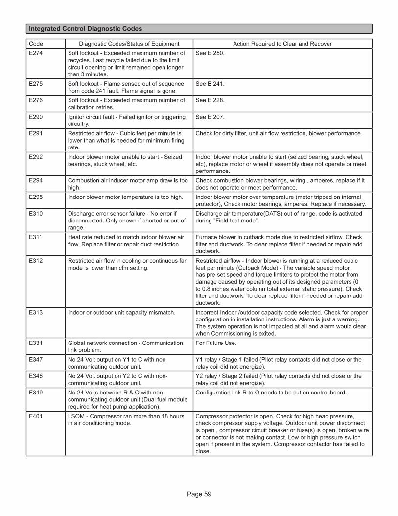
Page 59
Integrated Control Diagnostic Codes
Code Diagnostic Codes/Status of Equipment Action Required to Clear and RecoverE274 Soft lockout - Exceeded maximum number of
recycles. Last recycle failed due to the limit circuit opening or limit remained open longer than 3 minutes.
See E 250.
E275 Soft lockout - Flame sensed out of sequence from code 241 fault. Flame signal is gone.
See E 241.
E276 Soft lockout - Exceeded maximum number of calibration retries.
See E 228.
E290 Ignitor circuit fault - Failed ignitor or triggering circuitry.
See E 207.
E291 Restricted air flow - Cubic feet per minute is lower than what is needed for minimum firing rate.
Check for dirty filter, unit air flow restriction, blower performance.
E292 Indoor blower motor unable to start - Seized bearings, stuck wheel, etc.
Indoor blower motor unable to start (seized bearing, stuck wheel, etc), replace motor or wheel if assembly does not operate or meet performance.
E294 Combustion air inducer motor amp draw is too high.
Check combustion blower bearings, wiring , amperes, replace if it does not operate or meet performance.
E295 Indoor blower motor temperature is too high. Indoor blower motor over temperature (motor tripped on internal protector), Check motor bearings, amperes. Replace if necessary.
E310 Discharge error sensor failure - No error if disconnected. Only shown if shorted or out-of-range.
Discharge air temperature(DATS) out of range, code is activated during ”Field test mode”.
E311 Heat rate reduced to match indoor blower air flow. Replace filter or repair duct restriction.
Furnace blower in cutback mode due to restricted airflow. Check filter and ductwork. To clear replace filter if needed or repair/ add ductwork.
E312 Restricted air flow in cooling or continuous fan mode is lower than cfm setting.
Restricted airflow - Indoor blower is running at a reduced cubic feet per minute (Cutback Mode) - The variable speed motor has pre-set speed and torque limiters to protect the motor from damage caused by operating out of its designed parameters (0 to 0.8 inches water column total external static pressure). Check filter and ductwork. To clear replace filter if needed or repair/ add ductwork.
E313 Indoor or outdoor unit capacity mismatch. Incorrect Indoor /outdoor capacity code selected. Check for proper configuration in installation instructions. Alarm is just a warning. The system operation is not impacted at all and alarm would clear when Commissioning is exited.
E331 Global network connection - Communication link problem.
For Future Use.
E347 No 24 Volt output on Y1 to C with non-communicating outdoor unit.
Y1 relay / Stage 1 failed (Pilot relay contacts did not close or the relay coil did not energize).
E348 No 24 Volt output on Y2 to C with non-communicating outdoor unit.
Y2 relay / Stage 2 failed (Pilot relay contacts did not close or the relay coil did not energize).
E349 No 24 Volts between R & O with non-communicating outdoor unit (Dual fuel module required for heat pump application).
Configuration link R to O needs to be cut on control board.
E401 LSOM - Compressor ran more than 18 hours in air conditioning mode.
Compressor protector is open. Check for high head pressure, check compressor supply voltage. Outdoor unit power disconnect is open , compressor circuit breaker or fuse(s) is open, broken wire or connector is not making contact. Low or high pressure switch open if present in the system. Compressor contactor has failed to close.

Page 60
Integrated Control Diagnostic Codes
Code Diagnostic Codes/Status of Equipment Action Required to Clear and RecoverE402 LSOM - Outdoor unit system pressure trip. Compressor ran over 18 hours in air conditioning mode.E403 LSOM - Compressor short-cycling (Running less than
4 minutes).Outdoor unit pressure trip. Check dirty coil, fan motor, refrigerant charge.
E404 LSOM - Compressor rotor locked. Compressor short cycling (Running less than 4 minutes).E405 LSOM - Compressor open circuit. Check capacitor, wiring, hard start kit , replace
Compressor.E406 LSOM - Compressor open start circuit. Check compressor for hot (cool down) , check pressures,
fan motor etc. Replace compressor if unable to get circuit to close and compressor to operate.
E407 LSOM - Compressor open run circuit.E408 LSOM - Compressor contactor is welded.E409 LSOM - Compressor contactor is welded. Replace contactor.
Configuring Unit Size Codes
Power-Up - Number displayed represents by integrated control unit size code (furnace modeland capacity). If three horizontal bars are displayed followed by continuous E203, furnacecontrol does not recognize unit size code. Configure per the following:
Furnace control in IDLE mode No heating, cooling or indoor fan
operation)
To enter Field TestMode: push and holdbutton next to7-segment LED displayuntil solid dash symbolappears. Releasebutton.
Turn room thermostat to OFF
Push and hold button until the solid Psymbol is displayed on the 7-segmentLED. Release button. This mode allowsthe user to select a unit size code numberthat matches the furnace model size andcapacity.
Solid P startsblinking on7-Segment LED
Push and hold button. Integrated control willdisplay unit size code number for eachfurnace model for five seconds.
When the correct unit size code is displayed,release button. Selected code will flash for10-second period. During that period, hold pushbutton until code stops blinking (disappear for 2seconds). Integrated control will store code inmemory and will automatically exit Field Test Modeand reset. (If second period expires or push buttonis held less than five seconds, control willautomatically exit Field Test Mode and go intoIDLE mode without storing unit size code. If thishappens, programming function must be repeated).
Verify that the selected unit size code is correctand stored in non-volatile memory by cyclingthe 24 volt power to the furnace control. (At 24volt power-up of the furnace control, the7-segment LED will display a unit size code. Ifthree horizontal bars display, board does notrecognize unit size code. Programmingfunction must be repeated)
Yes No
IMPORTANT: Field replacement controls mayneed to be manually configured to validatefurnace unit size code.
FURNACE MODEL
SLP98DFXV-070-36B
SLP98DFXV-090-36C
SLP98DFXV-090-48C
SLP98DFXV-090-60C
SLP98DFXV-110-60C
UNIT SIZE CODE
H
J
L
n
o
−−−
_
_
P
P
−−−
If alarm is present,furnace control willdisplay error code. Ifalarm is not present soliddash starts blinking on7-segment LED display.
FINISHED

Page 61
Troubleshooting: Heating Sequence of Operation
IGNITION AND CALL FOR LOW FIRE WITH TWO-STAGETHERMOSTAT
Call For 2nd Stage Heat Call For Heat Satisfied
LimitSwitch
Closed?
LimitCloses Within 3
Minutes?NO
Soft Lockout:Error Code
Flashes
flashes
YES
RolloutCircuit
Closed?
LowPressureSwitchOpen?
LowPressure Switch
Closed Within 150Seconds?
HighPressureSwitchOpen?
YES
NO
NO
NO
NO
YES
NO
De-EnergizeGas Valve
De-EnergizeGas Valve
Error CodeFlashes
Error CodeFlashes
RolloutCircuit
Closes?
Hard Lockout:Error Code
Flashes
Error Code FlashesAfter 5 Seconds
Error Code FlashesAfter 5 Seconds
LIGHTOFF
SafetyCheck
After
(Low Heat Speed)
Verify ThereIs No Main Burner
Flame
YES
YES
Low PressureSwitch Opens
High PressureSwitch Opens
YES
NO Pressure SwitchCalibration
Pre-Purge15 Seconds
YES
Gas ValveEnergized
FlameSensed Within
4 seconds?
Gas ValveDe-energized
Interpurge(15 Seconds)
5thUnsuccessful
Trial?
Wait For IgnitionStabilization Delay
Post-Purge(20Seconds)
Soft Lockout:Error Code
FlashesYES
NO
NO
YES
Call ForHeat
Ends?
NO
YES
YES NOCALLFOR1STSTAGEHEAT
3A2
1
1
OR
CallFor
Heat?NO
4CalibrationsAttempted?
CalibrationSuccessful?
Wait5 minutes
NO
NOSoft Lockout:Error Code
FlashesYES
YES
YES
2
1
1
2
Set Target Firing RateBased on Thermostat
Signals Present
SOFT LOCKOUT IS RESET AUTOMATICALLY AFTER ONE HOUR WITH A CALL FOR HEAT ACTIVE,OR BY CYCLING THE CALL FOR HEAT, OR BY CYCLING POWER TO THE CONTROL.
HARD LOCKOU T IS RESET BY CYCLING POWER TO THE CONTROL.
1
2
Indoor blower OFF
Combustion AirInducer On(100% rate
speed)
Indoor BlowerON (100%)
Heat OFF Delay
Indoor Blower OFFAfter Heat OFF Delay(High Heat Speed)Combustion
Air InducerOn (100%rate speed)
Indoor BlowerON (70%)
Combustion AirInducer OFF
After Post-Purge
Indoor Blower OFF AfterHeat OFF Delay
Combustion AirInducer ON at 70%
Rate Speed
Ignitor ON20 Seconds
IndoorBlower
ON?
Indoor blower OFFAfter Heat OFF Delay
Indoor Blower DelayTimer Started
Ignition Trial Begins(Ignitor ON)
Ignitor OFF
Ignitor OFF
CombustionAir Inducer
OFF

Page 62
Troubleshooting: Heating Sequence of Operation (continued)
CALL FOR HIGH FIRE WITH TWO-STAGE THERMOSTAT
1st Callfor High
Fire?
Wait for Call for Heat Satisfied
2 StageThermostat
2nd StageRecognition Delay
(30 Seconds)
YES
HighPressure SwitchCloses Within10 Seconds?
NO Error CodeFlashes
NO
YES
Wait 5Minutes
3A
2
1
2
1
System will always light at 70% even if 2nd stage call for heat is in place
If the high pressure switch does not close within 5 attempts, the systemwill operate at low fire for the remainder of the call for heat at request
Combustion Air Inducer ON(100% Rate Speed)
Increase CombustionAir Inducer Speed
if Not at 100%Rate Speed
Adjust IndoorBlower to
Appropiate speed

Page 63
Troubleshooting: Heating Sequence of Operation (continued)
CALL FOR HIGH FIRE WITH TWO-STAGE THERMOSTAT
1st Callfor High
Fire?
Wait for Call for Heat Satisfied
2 StageThermostat
2nd StageRecognition Delay
(30 Seconds)
YES
HighPressure SwitchCloses Within10 Seconds?
NO Error CodeFlashes
NO
YES
Wait 5Minutes
3A
2
1
2
1
System will always light at 70% even if 2nd stage call for heat is in place
If the high pressure switch does not close within 5 attempts, the systemwill operate at low fire for the remainder of the call for heat at request
Combustion Air Inducer ON(100% Rate Speed)
Increase CombustionAir Inducer Speed
if Not at 100%Rate Speed
Adjust IndoorBlower to
Appropiate speed

Page 64
Troubleshooting: Heating Sequence of Operation (continued)
IGNITION AND CALL FOR HEAT WITH SINGLE-STAGE THERMOSTAT
Call For Heat Satisfied
LimitSwitch
Closed?
LimitCloses Within 3
Minutes?NO
Soft Lockout:Error Code
Flashes
flashes
YES
RolloutCircuit
Closed?
LowPressureSwitchOpen?
LowPressure Switch
Closed Within 150Seconds?
HighPressureSwitchOpen?
YES
NO
NO
NO
NO
YES
NO
De-EnergizeGas Valve
De-EnergizeGas Valve
Error CodeFlashes
Error CodeFlashes
RolloutCircuit
Closes?
Hard Lockout:Error Code
Flashes
Error Code FlashesAfter 5 Seconds
Error Code FlashesAfter 5 Seconds
LIGHTOFF
SafetyCheck
Verify ThereIs No Main Burner
Flame
YES
YES
Low PressureSwitch Opens
High PressureSwitch Opens
YES
NO
Pre-Purge15 Seconds
YES
Gas ValveEnergized
IgnitionTrial Begins
FlameSensed Within
4 seconds?
Gas ValveDe-energized
Interpurge(15 Seconds)
5thUnsuccessful
Trial?
Wait For IgnitionStabilization Delay
Post-Purge(20 Seconds)
Soft Lockout:Error Code
FlashesYES
NO
NO
YES
Call ForHeat
Ends?
NO
YES
YES NO
CALLFORHEAT
3B
1
4
Move to Mid Firing Rateand High Firing Rate after2nd and 3rd Stage Delays
(based on DIP Switch selections)
Pressure SwitchCalibration
CallFor
Heat?NO
4CalibrationsAttempted?
CalibrationSuccessful?
Wait5 minutes
NO
NOSoft Lockout:Error Code
FlashesYES
YES
YES
1
2
1
2
1
Set toLow Firing Rate
Indoor Blower OFF AfterHeat OFF Delay(Low Heat Speed)
Combustion AirInducer ON
(100%)
Indoor BlowerON
(100% Speed)
Indoor Blower OFFAfter Heat OFF Delay
(High Heat Speed)Combustion Air
Inducer ON(100%)
er ON(70%)
Combustion Air InducerOFF After Post-Purge
Indoor Blower OFF AfterHeat OFF Delay
Combustion Air Inducer ONat Ignition at 70% rate speed
IndoorBlower On?
Indoor Blower OFFAfter Heat OFF Delay
Ignitor ON20 Seconds
Ignitor ONIndoor Blower On
Delay Timer Started
Ignitor OFF
Combustion AirInducer OFF
Ignitor OFF
SOFT LOCKOUT IS RESET AUTOMATICALLY AFTER ONE HOUR WITH A CALL FOR HEATACTIVE,OR BY CYCLING THE CALL FOR HEAT, OR BY CYCLING POWER TO THE CONTROL.
HARD LOCKOUT IS RESET BY CYCLING POWER TO THE CONTROL

Page 65
Troubleshooting: Cooling Sequence of Operation
CALL FOR COOLING
1st Stage CoolingRequest Received
Energize 1st StageCooling Contactor
(Compressor & Fan)
2nd StageCooling
Request?
YES
2nd StageCooling Request
Still Active?
De-Energize 1stStage Cooling
Contactor(Compressor & Fan)
YES
1st StageCooling Request
Still Active?
NO
YES
YES
Energize 2nd StageCooling Contactor
(Compressor & Fan)
1st StageCooling Request
Still Active?
De-Energize 2ndStage Cooling
Contactor(Compressor & Fan)
Energize and
Low Cooling mode
(High Cooling mode)
(High Cooling mode)
Per Ramping Profile
NO
NO
YES
NO
5
1
2
1
2
2
2
1
Indoor Blower OnAfter 2-second delay
Energize Indoor Blower(Per Ramping Profile)
Energize Indoor Blower
Maintain Indoor Blower
Maintain Indoor Blower at
De-Energize Indoor Blower
2nd stage cooling operation requires a 2-stage thermostat, a 2-stage cooling system andon-board link W915 must be be cut. The control will not respond to a 2nd stage coolingrequest unless a 1st stage cooling request is active
Indoor blower cooling mode and high cooling mode have a specific ON, OFF and speedramping profiles. The specific profile is selected using the DIP switches on the control.
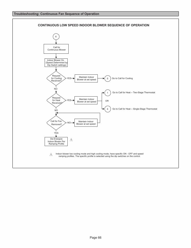
Page 66
Troubleshooting: Continuous Fan Sequence of Operation
CONTINUOUS LOW SPEED INDOOR BLOWER SEQUENCE OF OPERATION
(Speed Determined byDip Switch settings)
De-Energize
Ramping Profile
NO
Requestfor HeatReceived?
Requestfor CoolingReceived?
NO
YES
Call for FanRemoved?
YES
NO
YES Go to Call for Cooling
6
1
4
5
1
Call forContinuous Blower
Indoor Blower On
Maintain IndoorBlower at set speed
Maintain IndoorBlower at set speed OR
Maintain IndoorBlower at set speed
Indoor Blower Per
Indoor blower low cooling mode and high cooling mode, have specific ON - OFF and speedramping profiles. The specific profile is selected using the dip switches on the control.1
Go to Call for Heat -- Two-Stage Thermostat
Go to Call for Heat -- Single-Stage Thermostat
Page 67
Requirements for Commonwealth of Massachusetts
Modifications to NFPA-54, Chapter 10Revise NFPA-54 section 10.8.3 to add the following requirements:
For all side wall, horizontally vented, gas-fueled equip-ment installed in every dwelling, building or structure used in whole or in part for residential purposes, including those owned or operated by the Commonwealth and where the side wall exhaust vent termination is less than seven (7) feet above the finished grade in the area of the venting, in-cluding but not limited to decks and porches, the followingRequirements shall be satisfied:
1 - INSTALLATION OF CARBON MONOXIDE DETECTORS. At the time of installation of the side wall, horizontally vented, gas-fueled equipment, the installing plumber or gas fitter shall observe that a hard-wired carbon monoxide detector with an alarm and battery backup is installed on the floor level where the gas equipment is to be installed. In addition, the installing plumber or gasfitter shall observe that a battery-operated or hard-wired carbon monoxide detector with an alarm is installed on each additional level of the dwelling, building or structure served by the side wall, horizontally vented, gas-fueled equipment. It shall be the responsibility of the property owner to secure the services of qualified licensed professionals for the installation of hard-wired carbon monoxide detectors.a. In the event that the side wall, horizontally vented,
gas-fueled equipment is installed in a crawl space or an attic, the hard-wired carbon monoxide detector with alarm and battery back-up may be installed on the next adjacent floor level.
b. In the event that the requirements of this subdivision cannot be met at the time of completion of installation, the owner shall have a period of thirty (30) days to comply with the above requirements; provided, however, that during said thirty (30) day period, a battery-operated carbon monoxide detector with an alarm shall be installed.
2 - APPROVED CARBON MONOXIDE DETECTORS. Each carbon monoxide detector as required in accordance with the above provisions shall comply with NFPA 720 and be ANSI/UL 2034 listed and IAS certified.
3 - SIGNAGE. A metal or plastic identification plate shall be permanently mounted to the exterior of the building at a minimum height of eight (8) feet above grade directly in line with the exhaust vent terminal for the horizontally vented, gas-fueled heating appliance or equipment. The sign shall read, in print size no less than one-half (1/2) inch in size, “GAS VENT DIRECTLY BELOW. KEEP CLEAR OF ALL OBSTRUCTIONS.”
4 - INSPECTION. The state or local gas inspector of the side wall, horizontally vented, gas-fueled equipment shall not approve the installation unless, upon inspection, the inspector observes carbon monoxide detectors and signage installed in accordance with the provisions of 248 CMR 5.08(2)(a) 1 through 4.
EXEMPTIONS: The following equipment is exempt from 24 CMR 5.08(2)(a) 1 through 4:
1 - The equipment listed in Chapter 10 entitled “Equipment Not Required to Be Vented” in the most current edition of NFPA 54 as adopted by the Board; and
2 - Product Approved side wall, horizontally vented, gasfueled equipment installed in a room or structure separate from the dwelling, building or structure used in whole or in part for residential purposes.
MANUFACTURER REQUIREMENTS -GAS EQUIPMENT VENTING SYSTEM PROVIDED.When the manufacturer of Product Approved side wall, horizontally vented, gas-fueled equipment provides a venting system design or venting system components with the equipment, the instructions provided by the man-ufacturer for installation of the equipment and the venting system shall include:
1 - Detailed instructions for the installation of the venting system design or the venting system components: and
2 - A complete parts list for the venting system design or venting system.
MANUFACTURER REQUIREMENTS -GAS EQUIPMENT VENTING SYSTEM NOT PROVIDED.When the manufacturer of Product Approved side wall, horizontally vented, gas-fueled equipment does not pro-vide the parts for venting the flue gases, but identifies “special venting systems,” the following requirements shall be satisfied by the manufacturer:
1 - The referenced “special venting system” instructions shall be included with the appliance or equipment installation instructions; and
2 - The “special venting systems” shall be Product Approved by the Board, and the instructions for that system shall include a parts list and detailed installation instructions.
A copy of all installation instructions for all Product Approved side wall, horizontally vented, gas-fueled equipment, all venting instructions, all parts lists for venting instructions, and/or all venting design in-structions shall remain with the appliance

Page 68
FOR THE PROVINCE OF ONTARIO, HORIZONTAL SIDEWALL VENT APPLICATIONS ONLYFor exterior horizontal venting applications, the 2” X 1.5” reducer for 2” venting at the point where the exhaust pipe exits the structure is not required in direct or nondirect vent applications in the Province of Ontario. In these applications, the vent should be oriented such that the exhaust plume is unobjectionable. If the installation requires more separation be-tween the flue gases and the building structure, a reducer may be installed on the exhaust pipe to increase the flue gas velocity.
ADDENDUM FOR THE PROVINCE OF SASKATCHEWANSee below for venting in the province of Saskatchewan. Lennox approves the following termination for use in Saskatch-ewan Canada.
C
12”
D
B
A
2” (51MM)Vent Pipe
3” (76MM)Vent Pipe
12” (305 mm) Min. 12” (305 mm) Min.
6” (152 mm) Min.24” (610 mm) Max.
6” (152 mm) Max.
6” (152 mm) Min.24” (610 mm) Max.
6” (152 mm) Max.
A − Clearance above grade oraverage snow accumulation
B − Horizontal separation betweenintake and exhaust
C − Exhaust pipe length
D − Wall support distance from topof each pipe (intake/exhaust)
NOTE − Flue gas may be acidic and may adversely affect some building materials. If flue gases impingeon the building materials, a corrosion−resistant shield should be used to protect the wall surface. Theshield should be constructed using wood, sheet metal or other suitable material. All seams, joints, cracks,etc. in affected area, should be sealed using an appropriate sealant.
Per: Saskatchewan Code of Practice