
Installation Instructions Pro-Matic Installation kit
10
This kit includes the necessary brackets, levers and hardware required for the installation of the various the various Hurst Pro-Matic shifters (Cable and Shifter not included). This is an overview of the general installation procedures. For more detailed instructions please refer to the instruction sheet provided with the specific shifter part number that you are working with. These can also be found on our website. Note: All adjustments must be made with shifter and transmission in Neutral (N). All adjustments are critical and MUST be precise. Do not mix components (all parts including cable must be Hurst components provided in kit). If a shifter is removed and reinstalled, adjustments must be checked and re-adjusted. Always check cable for freedom of motion before connecting at shifter and transmission arm. Routing of cable should avoid sharp bends (permanent damage of cable will result.) Applications For 3-Speed Automatic Transmissions General Motors – Buick, Chevy, Olds and Pontiac using Turbo 250, 350 and 400 Ford/Mercury – All models using C-4 and C-6 Mopar – All models using A-904 and A-727 Torqueflites (except for push button models) AMC – All models using A-904 and A-727 Torque Command Shifter Installation 1. Place the column shift lever in the Park position. Remove the drive pin that holds the lever to the column, then remove this lever from the column. For factory console shifters: Remove shifting mechanism and any cables, cable bracket or rods that are attached to the shifter and/or transmission. Note: Console modification or console removal may be necessary depending on the vehicle and space available. Use a metal plate to cover the hole in the floor that was left from the factory floor shifter. For vehicles equipped with a steering column lock, pace the column shift into the Park position and secure the shift lever linkage (located in the engine compartment or under the instrument panel) to a rigid frame member or support to prevent movement. This will allow the steering wheel to lock in the Park position as it should when the key is removed. Caution: If this lever is secured too tight, the ignition will be hard to operate. Technical Support (707) 544-4761 1 www.hurst-shifters.com Installation Instructions Pro-Matic Installation kit Catalog# 3730003
Transcript of Installation Instructions Pro-Matic Installation kit
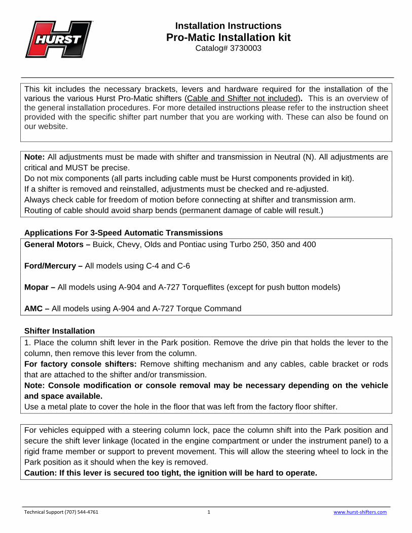
This kit includes the necessary brackets, levers and hardware required for the installation of the various the various Hurst Pro-Matic shifters (Cable and Shifter not included). This is an overview of the general installation procedures. For more detailed instructions please refer to the instruction sheet provided with the specific shifter part number that you are working with. These can also be found on our website.
Note: All adjustments must be made with shifter and transmission in Neutral (N). All adjustments are critical and MUST be precise. Do not mix components (all parts including cable must be Hurst components provided in kit). If a shifter is removed and reinstalled, adjustments must be checked and re-adjusted. Always check cable for freedom of motion before connecting at shifter and transmission arm. Routing of cable should avoid sharp bends (permanent damage of cable will result.) Applications For 3-Speed Automatic Transmissions General Motors – Buick, Chevy, Olds and Pontiac using Turbo 250, 350 and 400 Ford/Mercury – All models using C-4 and C-6 Mopar – All models using A-904 and A-727 Torqueflites (except for push button models) AMC – All models using A-904 and A-727 Torque Command Shifter Installation 1. Place the column shift lever in the Park position. Remove the drive pin that holds the lever to the column, then remove this lever from the column. For factory console shifters: Remove shifting mechanism and any cables, cable bracket or rods that are attached to the shifter and/or transmission. Note: Console modification or console removal may be necessary depending on the vehicle and space available. Use a metal plate to cover the hole in the floor that was left from the factory floor shifter. For vehicles equipped with a steering column lock, pace the column shift into the Park position and secure the shift lever linkage (located in the engine compartment or under the instrument panel) to a rigid frame member or support to prevent movement. This will allow the steering wheel to lock in the Park position as it should when the key is removed. Caution: If this lever is secured too tight, the ignition will be hard to operate.
Technical Support (707) 544-4761 1 www.hurst-shifters.com
Installation Instructions Pro-Matic Installation kit
Catalog# 3730003
2. Remove the knob and console assembly from the shifter mechanism. 3. Determine a comfortable position for the shifter assembly on the centerline of the transmission tunnel allowing clearance for seat travel and shift lever travel between dashboard when shifting into Park position. Cut a small section of the carpet where the shifter mechanism will mount to the transmission tunnel. Make sure there are no wires under the carpet. After the carpet is cut, position shifter in desired location, mark and drill 4 mounting holes using a 9/32” drill bit.
5. Install the rubber grommet in the 1 ½” cable hole located in the floor. 6. Install the shifter mechanism into the vehicle using the 4 suppled ¼” x 1” bolts, nuts and washers.
Technical Support (707) 544-4761 2 www.hurst-shifters.com
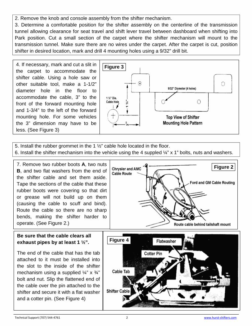
4. If necessary, mark and cut a slit in the carpet to accommodate the shifter cable. Using a hole saw or other suitable tool, make a 1-1/2” diameter hole in the floor to accommodate the cable, 3” to the front of the forward mounting hole and 1-3/4” to the left of the forward mounting hole. For some vehicles the 3” dimension may have to be less. (See Figure 3)
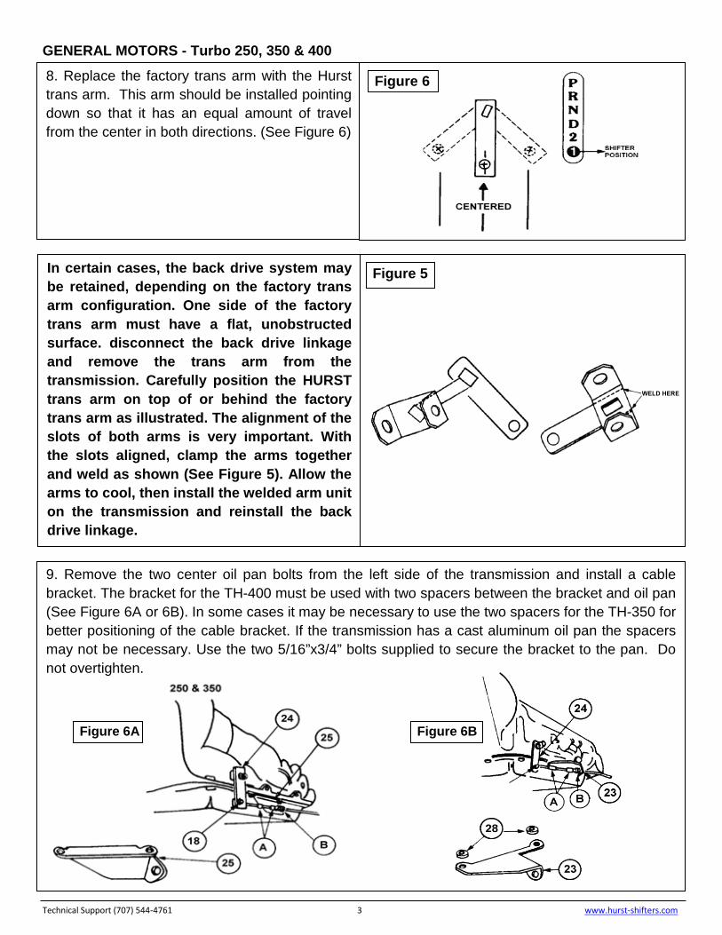
7. Remove two rubber boots A, two nuts B, and two flat washers from the end of the shifter cable and set them aside. Tape the sections of the cable that these rubber boots were covering so that dirt or grease will not build up on them (causing the cable to scuff and bind). Route the cable so there are no sharp bends, making the shifter harder to operate. (See Figure 2.)
Figure 3
Be sure that the cable clears all exhaust pipes by at least 1 ½”.
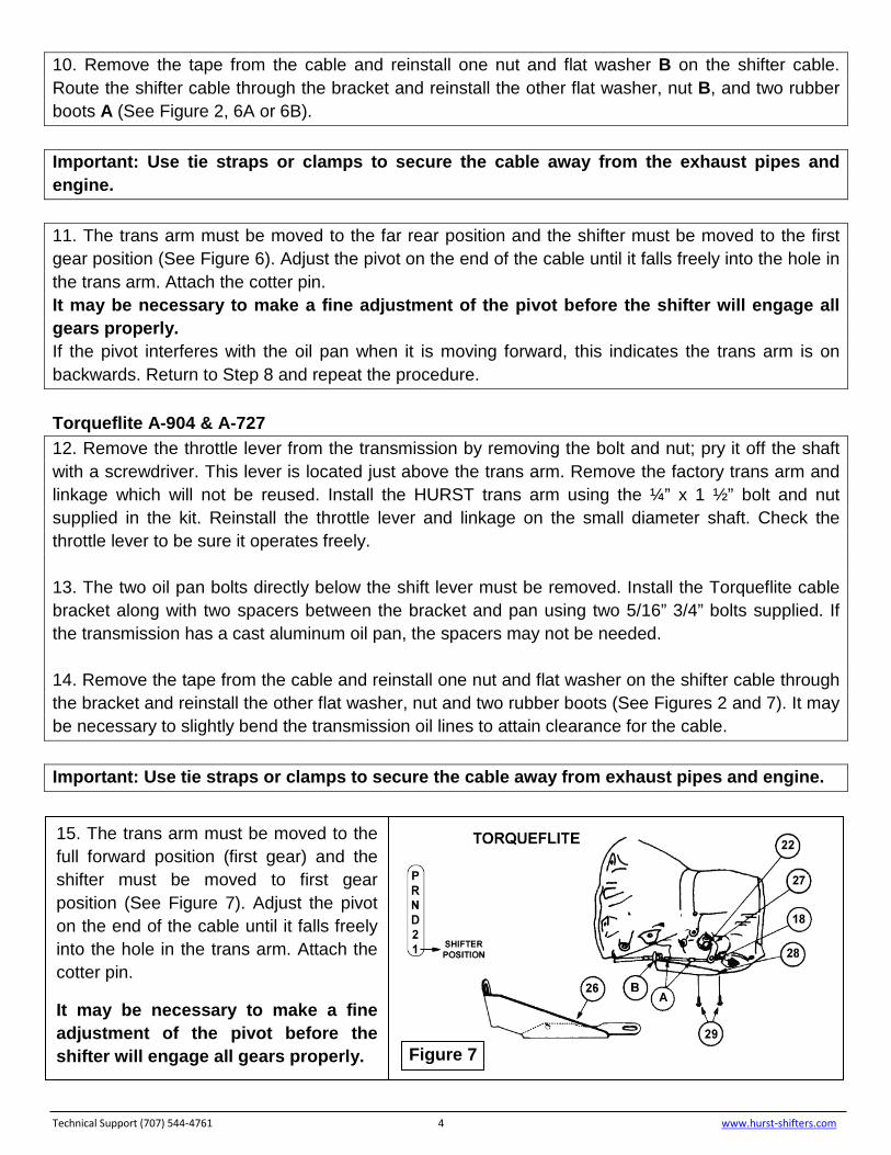
The end of the cable that has the tab attached to it must be installed into the slot to the inside of the shifter mechanism using a supplied ¼” x ¾” bolt and nut. Slip the flattened end of the cable over the pin attached to the shifter and secure it with a flat washer and a cotter pin. (See Figure 4)
Figure 2
Figure 4
GENERAL MOTORS - Turbo 250, 350 & 400 Technical Support (707) 544-4761 3 www.hurst-shifters.com
8. Replace the factory trans arm with the Hurst trans arm. This arm should be installed pointing down so that it has an equal amount of travel from the center in both directions. (See Figure 6)
Figure 6
In certain cases, the back drive system may be retained, depending on the factory trans arm configuration. One side of the factory trans arm must have a flat, unobstructed surface. disconnect the back drive linkage and remove the trans arm from the transmission. Carefully position the HURST trans arm on top of or behind the factory trans arm as illustrated. The alignment of the slots of both arms is very important. With the slots aligned, clamp the arms together and weld as shown (See Figure 5). Allow the arms to cool, then install the welded arm unit on the transmission and reinstall the back drive linkage.
9. Remove the two center oil pan bolts from the left side of the transmission and install a cable bracket. The bracket for the TH-400 must be used with two spacers between the bracket and oil pan (See Figure 6A or 6B). In some cases it may be necessary to use the two spacers for the TH-350 for better positioning of the cable bracket. If the transmission has a cast aluminum oil pan the spacers may not be necessary. Use the two 5/16”x3/4” bolts supplied to secure the bracket to the pan. Do not overtighten.
Figure 6A Figure 6B
Figure 5
10. Remove the tape from the cable and reinstall one nut and flat washer B on the shifter cable. Route the shifter cable through the bracket and reinstall the other flat washer, nut B, and two rubber boots A (See Figure 2, 6A or 6B). Important: Use tie straps or clamps to secure the cable away from the exhaust pipes and engine. 11. The trans arm must be moved to the far rear position and the shifter must be moved to the first gear position (See Figure 6). Adjust the pivot on the end of the cable until it falls freely into the hole in the trans arm. Attach the cotter pin. It may be necessary to make a fine adjustment of the pivot before the shifter will engage all gears properly. If the pivot interferes with the oil pan when it is moving forward, this indicates the trans arm is on backwards. Return to Step 8 and repeat the procedure. Torqueflite A-904 & A-727 12. Remove the throttle lever from the transmission by removing the bolt and nut; pry it off the shaft with a screwdriver. This lever is located just above the trans arm. Remove the factory trans arm and linkage which will not be reused. Install the HURST trans arm using the ¼” x 1 ½” bolt and nut supplied in the kit. Reinstall the throttle lever and linkage on the small diameter shaft. Check the throttle lever to be sure it operates freely. 13. The two oil pan bolts directly below the shift lever must be removed. Install the Torqueflite cable bracket along with two spacers between the bracket and pan using two 5/16” 3/4” bolts supplied. If the transmission has a cast aluminum oil pan, the spacers may not be needed. 14. Remove the tape from the cable and reinstall one nut and flat washer on the shifter cable through the bracket and reinstall the other flat washer, nut and two rubber boots (See Figures 2 and 7). It may be necessary to slightly bend the transmission oil lines to attain clearance for the cable. Important: Use tie straps or clamps to secure the cable away from exhaust pipes and engine. Technical Support (707) 544-4761 4 www.hurst-shifters.com
15. The trans arm must be moved to the full forward position (first gear) and the shifter must be moved to first gear position (See Figure 7). Adjust the pivot on the end of the cable until it falls freely into the hole in the trans arm. Attach the cotter pin.
It may be necessary to make a fine adjustment of the pivot before the shifter will engage all gears properly. Figure 7
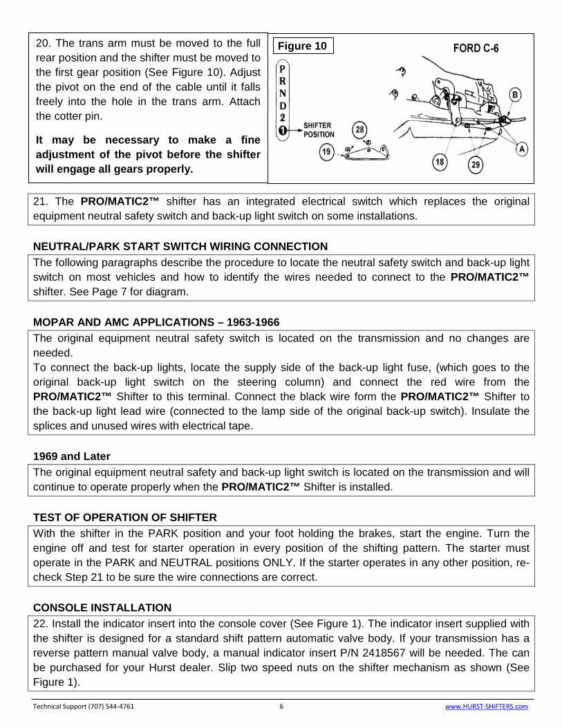
Ford C4 & C6 18. C-3/C-4: The two lower bolts E on the rear servo cover F, must be removed to install the cable bracket on the transmission. Install the cable bracket with these same two bolts and tighten (See Figure 9). C-6: The two oil pan bolts at the left rear corner must be removed to install the cable bracket and two spacers. They are installed between the bracket and the pan using the 5/16” x 3/4" bolts supplied (See Figure 10). If the transmission has a cast aluminum oil pan the spacers may not be necessary. 19. Remove the tape from the cable and reinstall one nut and flat washer B on the shifter cable. Route the cable through the bracket and reinstall the other flat washer, nut B, and two rubber boots A (See Figures 2 and 10). Important: Use tie straps or clamps to secure the cable away from exhaust pipes and engine. Technical Support (707) 544-4761 5 www.hurst-shifters.com
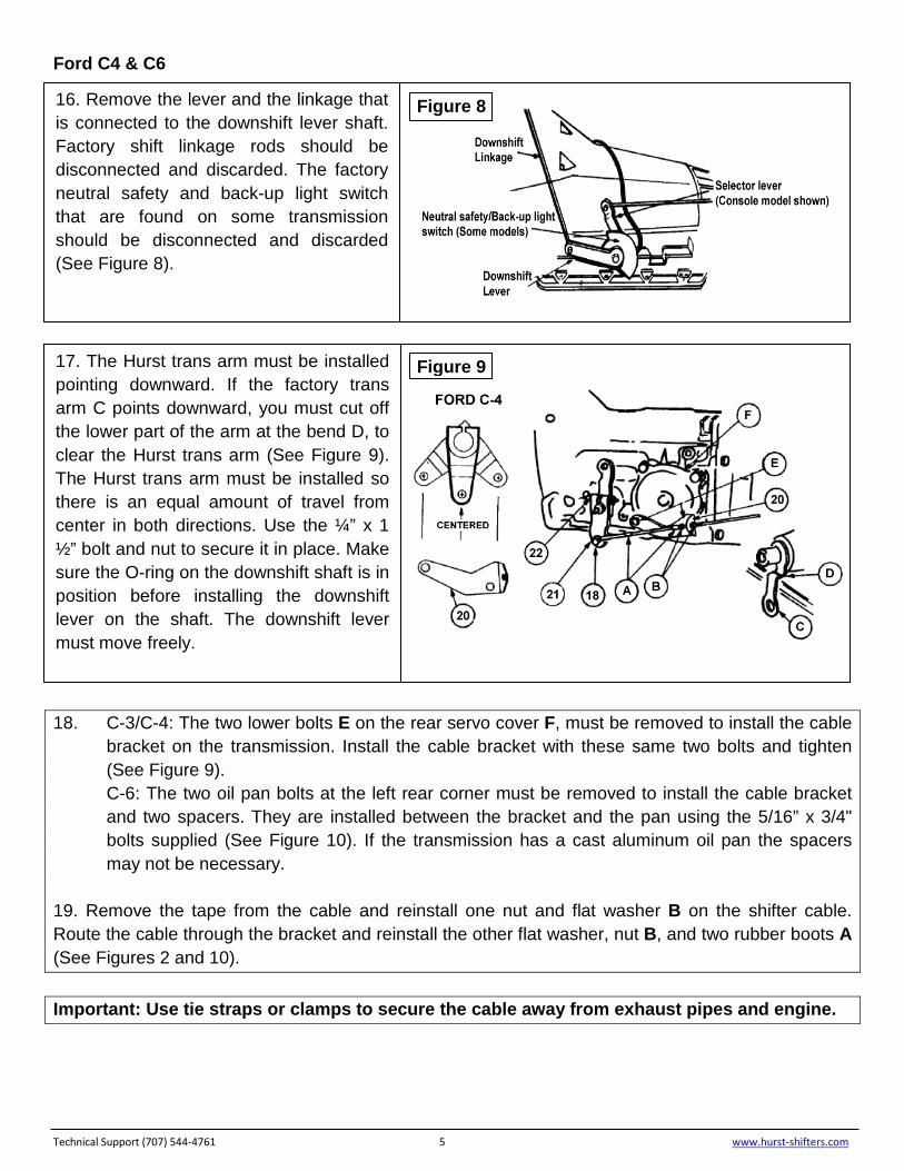
16. Remove the lever and the linkage that is connected to the downshift lever shaft. Factory shift linkage rods should be disconnected and discarded. The factory neutral safety and back-up light switch that are found on some transmission should be disconnected and discarded (See Figure 8).
Figure 8
17. The Hurst trans arm must be installed pointing downward. If the factory trans arm C points downward, you must cut off the lower part of the arm at the bend D, to clear the Hurst trans arm (See Figure 9). The Hurst trans arm must be installed so there is an equal amount of travel from center in both directions. Use the ¼” x 1 ½” bolt and nut to secure it in place. Make sure the O-ring on the downshift shaft is in position before installing the downshift lever on the shaft. The downshift lever must move freely.
Figure 9
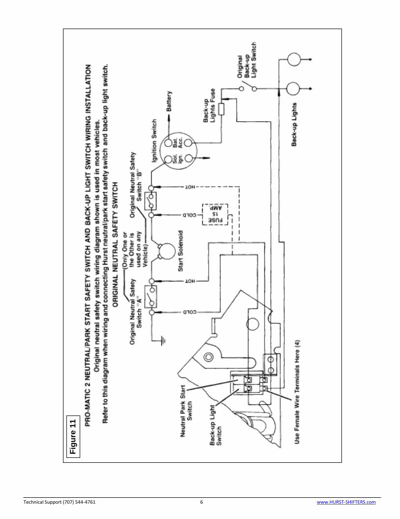
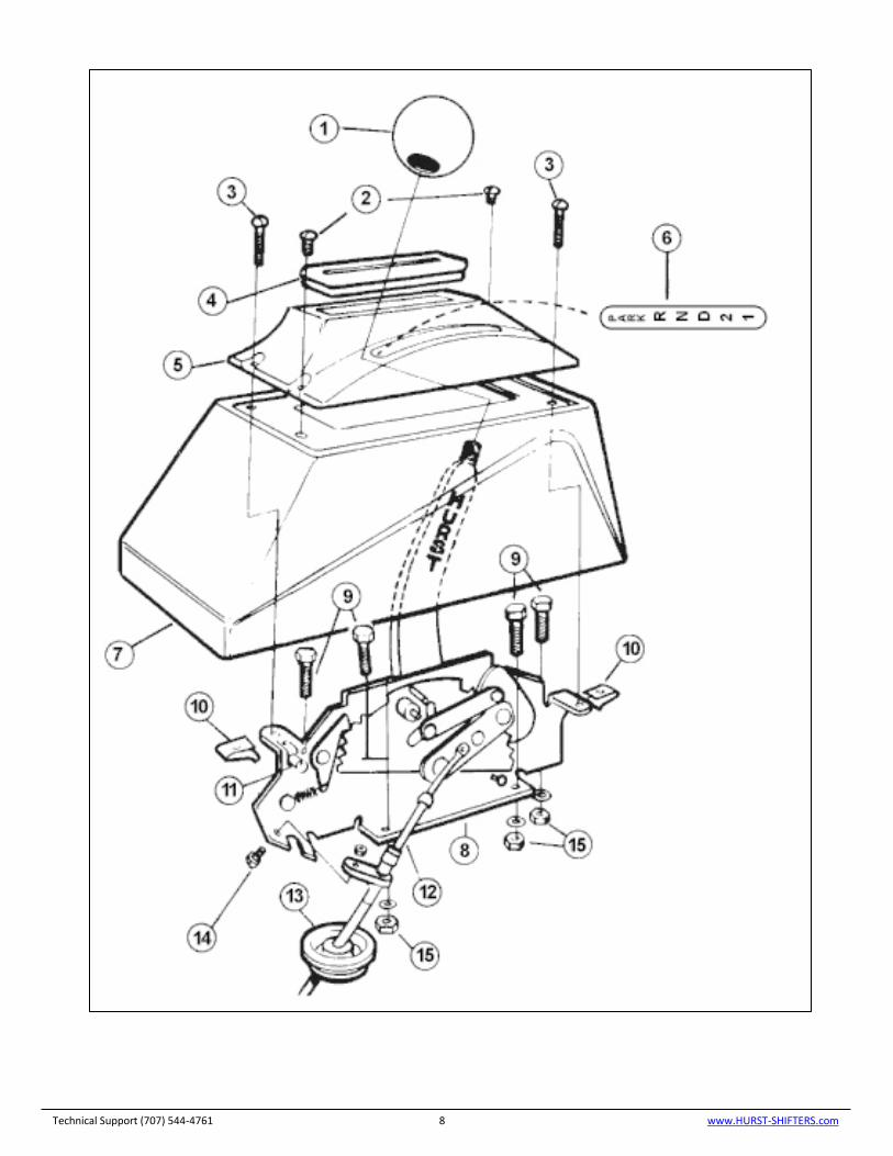
21. The PRO/MATIC2™ shifter has an integrated electrical switch which replaces the original equipment neutral safety switch and back-up light switch on some installations. NEUTRAL/PARK START SWITCH WIRING CONNECTION The following paragraphs describe the procedure to locate the neutral safety switch and back-up light switch on most vehicles and how to identify the wires needed to connect to the PRO/MATIC2™ shifter. See Page 7 for diagram. MOPAR AND AMC APPLICATIONS – 1963-1966 The original equipment neutral safety switch is located on the transmission and no changes are needed. To connect the back-up lights, locate the supply side of the back-up light fuse, (which goes to the original back-up light switch on the steering column) and connect the red wire from the PRO/MATIC2™ Shifter to this terminal. Connect the black wire form the PRO/MATIC2™ Shifter to the back-up light lead wire (connected to the lamp side of the original back-up switch). Insulate the splices and unused wires with electrical tape. 1969 and Later The original equipment neutral safety and back-up light switch is located on the transmission and will continue to operate properly when the PRO/MATIC2™ Shifter is installed. TEST OF OPERATION OF SHIFTER With the shifter in the PARK position and your foot holding the brakes, start the engine. Turn the engine off and test for starter operation in every position of the shifting pattern. The starter must operate in the PARK and NEUTRAL positions ONLY. If the starter operates in any other position, re-check Step 21 to be sure the wire connections are correct. CONSOLE INSTALLATION 22. Install the indicator insert into the console cover (See Figure 1). The indicator insert supplied with the shifter is designed for a standard shift pattern automatic valve body. If your transmission has a reverse pattern manual valve body, a manual indicator insert P/N 2418567 will be needed. The can be purchased for your Hurst dealer. Slip two speed nuts on the shifter mechanism as shown (See Figure 1).
Technical Support (707) 544-4761 6 www.HURST-SHIFTERS.com
20. The trans arm must be moved to the full rear position and the shifter must be moved to the first gear position (See Figure 10). Adjust the pivot on the end of the cable until it falls freely into the hole in the trans arm. Attach the cotter pin.
It may be necessary to make a fine adjustment of the pivot before the shifter will engage all gears properly.
Figure 10
24. Install the console and console cover in position over the shifter mechanism and secure them with two #8 x 1 ¾” and two #8 x ¾” self-tapping screws. Slip the rubber boot over the handle and work it into the console cover. Reinstall the shifter knob. SHIFTER OPERATION STRAIGHT GATE MODE The upper position of the shifter operates the straight gate mode of Park, Reverse and Neutral. The handle moves straight backward from Park to Neutral but must be lifted to clear the safety stop between Park and Reverse. Once in Reverse the handle drops and the shifter is ready for a straight pull back to Neutral. When Neutral is engaged the handle will drop again and will be engaged in the ratchet mode.
RATCHET SHIFT MODE
Technical Support (707) 544-4761 7 www.HURST-SHIFTERS.com
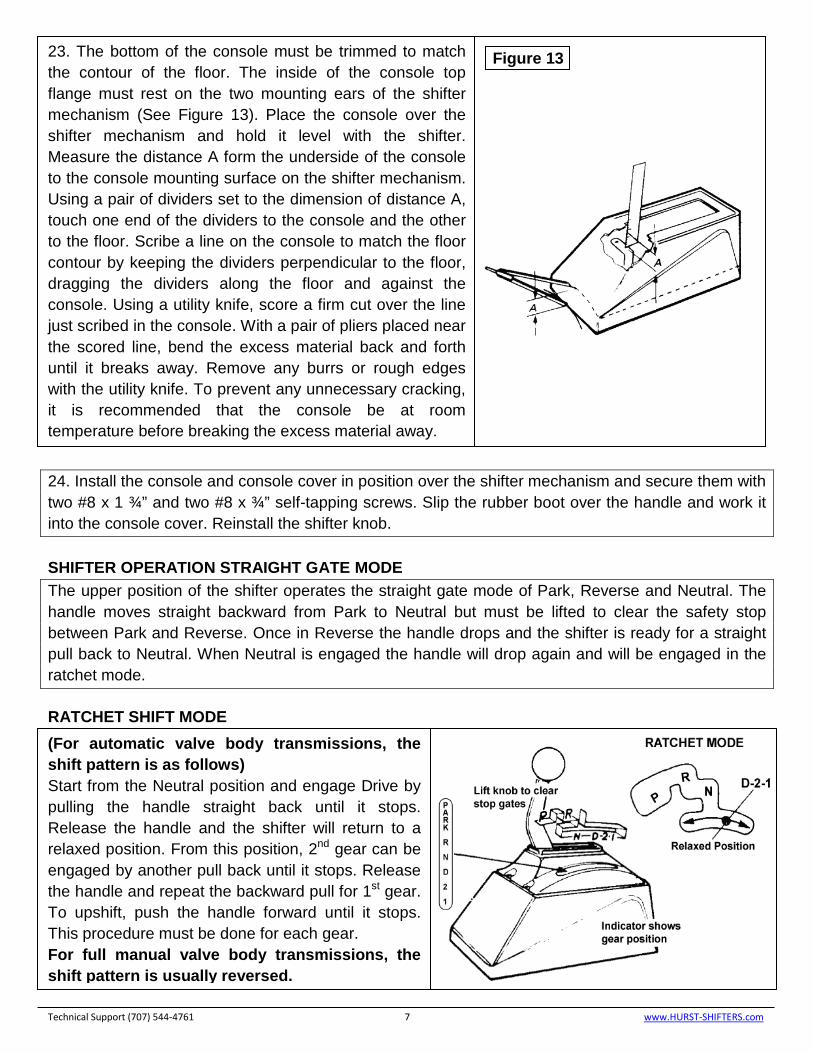
23. The bottom of the console must be trimmed to match the contour of the floor. The inside of the console top flange must rest on the two mounting ears of the shifter mechanism (See Figure 13). Place the console over the shifter mechanism and hold it level with the shifter. Measure the distance A form the underside of the console to the console mounting surface on the shifter mechanism. Using a pair of dividers set to the dimension of distance A, touch one end of the dividers to the console and the other to the floor. Scribe a line on the console to match the floor contour by keeping the dividers perpendicular to the floor, dragging the dividers along the floor and against the console. Using a utility knife, score a firm cut over the line just scribed in the console. With a pair of pliers placed near the scored line, bend the excess material back and forth until it breaks away. Remove any burrs or rough edges with the utility knife. To prevent any unnecessary cracking, it is recommended that the console be at room temperature before breaking the excess material away.
Figure 13
(For automatic valve body transmissions, the shift pattern is as follows) Start from the Neutral position and engage Drive by pulling the handle straight back until it stops. Release the handle and the shifter will return to a relaxed position. From this position, 2nd gear can be engaged by another pull back until it stops. Release the handle and repeat the backward pull for 1st gear. To upshift, push the handle forward until it stops. This procedure must be done for each gear. For full manual valve body transmissions, the shift pattern is usually reversed.

IMPORTANT: RETAIN THESE INSTRUCTIONS FOR FUTURE REFERENCE Technical Service
A highly trained technical service department is maintained by Hurst Performance to answer your technical questions, provide additional product information and offer various recommendations.
Technical service calls, correspondence, and warranty questions should be directed to:
Hurst Performance Products
(707) 544-4761
www.Hurst-Shifters.com
Technical Support (707) 544-4761 9 www.HURST-SHIFTERS.com