Installation Instructions Oven Support Shelf (OSS) · Oven Support Shelf (OSS) make cutout in oven...
2
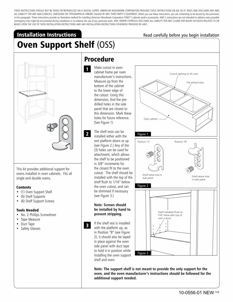
10-0533 7/08 This kit provides additional support for ovens installed in oven cabinets. Fits all single and double ovens. Contents • (1) Oven Support Shelf • (6) Shelf Supports • (6) Shelf Support Screws Tools Needed • No. 2 Phillips Screwdriver • Tape Measure • Duct Tape • Safety Glasses Oven Support Shelf (OSS) Make cutout in oven cabinet frame per oven manufacturer’s instructions. Measure up from the bottom of the cabinet to the lower edge of the cutout. Using this dimension, find the pre- drilled holes in the side panel that are closest to this dimension. Mark these holes for future reference. (See Figure 1) The shelf rests can be installed either with the rest platform down or up (see Figure 2.) Any of the (3) holes can be used for attachment, which allows the shelf to be positioned in 3/8” increments for the closest fit to the oven cutout. The shelf should be installed with the top of the shelf flush to 1/16” below the oven cutout, and can be shimmed if necessary (see Figure 3.) Note: Screws should be installed by hand to prevent stripping. If the shelf rest is installed with the platform up, as in Position “B” (see Figure 2), it should also be taped in place against the oven side panel with duct tape to hold it in position while installing the oven support shelf and oven. Note: The support shelf is not meant to provide the only support for the oven, and the oven manufacturer’s instructions should be followed for the additional support needed. 1 2 Installation Instructions Readcarefullybeforeyoubegininstallation THESE INSTRUCTIONS SHOULD NOT BE FAXED OR REPRODUCED ON A DIGITAL COPIER. AMERICAN WOODMARK CORPORATION PROVIDES THESE INSTRUCTIONS ON AN “AS IS” BASIS AND DISCLAIMS ANY AND ALL LIABILITY FOR ANY INACCURACIES, OMISSIONS OR TYPOGRAPHICAL ERRORS CAUSED BY ANY THIRD PARTY’S EQUIPMENT. When you use these instructions, you are consenting to be bound by the provisions in this paragraph. These instructions provide an illustrative method for installing American Woodmark Corporation (“AWC”) cabinets and/or accessories. AWC’s instructions are not intended to address every possible contingency that might be encountered during installation or to endorse the use of any particular tools. AWC HEREBY EXPRESSLY DISCLAIMS ALL LIABILITY FOR ANY CLAIMS FOR INJURY OR DEATH RELATED TO OR BASED UPON THE USE OF THESE INSTALLATION INSTRUCTIONS AND ANY INSTALLATION INSTRUCTIONS OTHERWISE PROVIDED BY AWC. Procedure Figure3 Figure2 Shelf below hole in side panel 3 Figure1 Oven cabinet Cutout opening to fit oven Pre-drilled holes Shelf above hole in side panel Position "A" Position "B" Shelf installed flush to 1/16" below with top of oven cutout 10-0556-01 NEW
Transcript of Installation Instructions Oven Support Shelf (OSS) · Oven Support Shelf (OSS) make cutout in oven...
10-0533 7/08
This kit provides additional support for ovens installed in oven cabinets. fits all single and double ovens.
Contents• (1) oven support shelf• (6) shelf supports• (6) shelf support screws
Tools Needed• no. 2 phillips screwdriver• Tape measure• duct Tape• safety glasses
Oven Support Shelf (OSS)
make cutout in oven cabinet frame per oven manufacturer’s instructions.measure up from the bottom of the cabinet to the lower edge of the cutout. using this dimension, find the pre-drilled holes in the side panel that are closest to this dimension. mark these holes for future reference. (see figure 1)
The shelf rests can be installed either with the rest platform down or up (see figure 2.) Any of the (3) holes can be used for attachment, which allows the shelf to be positioned in 3/8” increments for the closest fit to the oven cutout. The shelf should be installed with the top of the shelf flush to 1/16” below the oven cutout, and can be shimmed if necessary (see figure 3.)
Note: Screws should be installed by hand to prevent stripping.
if the shelf rest is installed with the platform up, as in position “b” (see figure 2), it should also be taped in place against the oven side panel with duct tape to hold it in position while installing the oven support shelf and oven.
Note: The support shelf is not meant to provide the only support for the oven, and the oven manufacturer’s instructions should be followed for the additional support needed.
1
2
Installation Instructions � Read�carefully�before�you�begin�installation
These insTrucTions should noT be fAxed or reproduced on A digiTAl copier. AmericAn WoodmArk corporATion provides These insTrucTions on An “As is” bAsis And disclAims Any And All liAbiliTy for Any inAccurAcies, omissions or TypogrAphicAl errors cAused by Any Third pArTy’s equipmenT. When you use these instructions, you are consenting to be bound by the provisions in this paragraph. These instructions provide an illustrative method for installing American Woodmark corporation (“AWc”) cabinets and/or accessories. AWc’s instructions are not intended to address every possible contingency that might be encountered during installation or to endorse the use of any particular tools. AWc hereby expressly disclAims All liAbiliTy for Any clAims for inJury or deATh relATed To or bAsed upon The use of These insTAllATion insTrucTions And Any insTAllATion insTrucTions oTherWise provided by AWc.
Procedure
Figure�3
Figure�2
Shelf below hole in side panel
3
Figure�1
Oven cabinet
Cutout opening to fit oven
Pre-drilled holes
Shelf above hole in side panel
Position "A" Position "B"
Shelf installed flush to 1/16" below with top of oven cutout
10-0556-01 NEW

10-0533 7/08
Instrucciones de instalación �Lea�las�instrucciones�cuidadosamente�antes�de�comenzar�la�instalación.
estas instrucciones no deben ser enviadas por fax o reproducidas en una copiadora digital. American Woodmark corporation proporciona estas instrucciones “como están” y se deslinda de cualquier y toda responsabilidad de imprecisiones, omisiones o errores tipográficos ocasionados por el equipo de un tercero. cuando utilice estas instrucciones, está de acuerdo en sujetarse a las disposiciones del presente párrafo. estas instrucciones proporcionan un método ilustrativo para instalar los gabinetes y/o accesorios de Woodmark corporation (“AWc”). las instrucciones de AWc no pretenden abordar todas las contingencias posibles que puedan surgir durante la instalación, tampoco endosan el uso de alguna herramienta en particular. por medio del presenTe AWc rechAZA TodAs lAs responsAbilidAdes de cuAlquier reclAmo por lesiones o muerTe relAcionAdos con o con bAse en el uso de esTAs insTrucciones de insTAlAcciÓn A menos que lo especifique AWc.
este kit proporciona soporte adicional para hornos que se instalan en gabinetes. se ajusta a todos los hornos simples y dobles.
Contenido:• (1) estante de soporte para horno• (6) soporte para estante• (6) Tornillos de soporte para estante
Herramientas necesarias• destornillador phillips no. 2• cinta métrica• cinta aislante• gafas de seguridad
Estante de soporte para horno (OSS)
haga el corte en la estructura del gabinete como lo indican las instrucciones del fabricante. mida hacia arriba a partir del fondo del gabinete al borde inferior del corte. con la ayuda de esta medida, busque los agujeros pretaladrados en el panel lateral que estén lo más cerca de esta medida. marque estos agujeros para referencia futura. (consulte la figura 1)
los descansos del estante pueden instalarse con la plataforma de descanso hacia abajo o hacia arriba ( ver figura 2.) cualquiera de los tres (3) agujeros se pueden usar para unirlo, esto permite al estante estar en una posición de incrementos de 3/8” para obtener el ajuste más cercano al corte del horno. el estante debe instalarse con la parte superior al ras a 1/16” por debajo del corte del horno y se puede acuñar de ser necesario (ver la figura 3).
Aviso: Los tornillos deben instalarse a mano para evitar que se desarme.
si se instala el descanso del estante con la plataforma hacia arriba, como se indica en la posición “b” (ver figura 2), también debe colocarse cinta contra el panel lateral del horno para sostenerlo en posición mientras se instala el soporte del horno y el horno.
Aviso: El estante de soporte no está diseñado para proporcionar el único soporte para el horno y las instrucciones del fabricante del horno deben seguirse si se necesita soporte adicional.
1
2
Procedimiento
Figura�3
Figura�2
Coloque el estante por debajo del agujero en el panel lateral
3
Figura�1
Gabinete para horno
Apertura del corte que se ajusta al horno
Agujeros pretaladrados
Estante sobre el agujero en el panel lateral
Posición “A” Posición “B”
Instalar el estante al ras 1/16" por debajo con la parte superior del corte del horno
10-0556-02 NEW


![MICROWAVE OVEN - Sears Parts Direct · 2008-01-21 · [] Place the microwave oven on a cart, counter, table or shelf that is strong enough to hold the microwave oven and the food](https://static.fdocuments.in/doc/165x107/5f4e855446e2cf2fd1308ad6/microwave-oven-sears-parts-direct-2008-01-21-place-the-microwave-oven-on.jpg)