INSTALLATION INSTRUCTIONS Modular Blower … current editions of the National Electrical Code (NEC)...
12
April 2012 Specifications subject to change without notice. X40159 Rev. D These instructions must be read and understood completely before attempting installation. SAFETY CONSIDERATIONS Improper installation, adjustment, alteration, service, maintenance, or use can cause explosion, fire, electrical shock, or other conditions which may cause death, personal injury, or property damage. Consult a qualified installer, service agency, or your distributor or branch for information or assistance. The qualified installer or agency must use factory-authorized kits or accessories when modifying this product. Refer to the individual instructions packaged with the kits or accessories when installing. Follow all safety codes. Wear safety glasses, protective clothing, and work gloves. Use quenching cloth for brazing operations. Have fire extinguisher available. Read these instructions thoroughly and follow all warnings or cautions included in literature and attached to the unit. Consult local building codes, the current editions of the National Electrical Code (NEC) NFPA- 70. In Canada refer to the current editions of the Canadian Electrical Code CSA C22.1 Recognize safety information. This is the safety-alert symbol . When you see this symbol on the unit and in instructions or manuals, be alert to the potential for personal injury. Understand these signal words; DANGER, WARNING, and CAUTION. These words are used with the safety-alert symbol. DANGER identifies the most serious hazards which will result in severe personal injury or death. WARNING signifies hazards which could result in personal injury or death. CAUTION is used to identify unsafe practices which may result in minor personal injury or product and property damage. NOTE is used to highlight suggestions which will result in enhanced installation, reliability or operation. TABLE OF CONTENTS General Information/Installation .......................................... 2 Installation ............................................................................. 2 Vertical/Horizontal Installation ............................................. 3 Ductwork Connection ............................................................ 4 Filter Installation.................................................................... 4 Electrical Connection ............................................................. 4 Blower Performance.............................................................. 8 Sequence of Operation........................................................ 10 Wiring Diagram.................................................................... 11 Replacement Parts .............................................................. 12 WARNING ELECTRICAL SHOCK HAZARD Failure to turn off electric power could result in personal injury or death. Before installing or servicing system, turn off main power to the system. There may be more than one disconnect switch, including accessory heater(s). INSTALLATION INSTRUCTIONS Modular Blower (Electric furnace) MF080014C, MF120017C, MF160021C, MF200024C
Transcript of INSTALLATION INSTRUCTIONS Modular Blower … current editions of the National Electrical Code (NEC)...

April 2012 Specifications subject to change without notice. X40159 Rev. D
These instructions must be read and understood completely before attempting installation.
SAFETY CONSIDERATIONS
Improper installation, adjustment, alteration, service, maintenance, or use can cause explosion, fire, electrical shock, or other conditions which may cause death, personal injury, or property damage. Consult a qualified installer, service agency, or your distributor or branch for information or assistance. The qualified installer or agency must use factory-authorized kits or accessories when modifying this product. Refer to the individual instructions packaged with the kits or accessories when installing. Follow all safety codes. Wear safety glasses, protective clothing, and work gloves. Use quenching cloth for brazing operations. Have fire extinguisher available. Read these instructions thoroughly and follow all warnings or cautions included in literature and attached to the unit. Consult local building codes, the current editions of the National Electrical Code (NEC) NFPA-70.
In Canada refer to the current editions of the Canadian Electrical Code CSA C22.1 Recognize safety information.
This is the safety-alert symbol . When you see this symbol on the unit and in instructions or manuals, be alert to the potential for personal injury. Understand these signal words; DANGER, WARNING, and CAUTION. These words are used with the safety-alert symbol. DANGER identifies the most serious hazards which will result in severe personal injury or death. WARNING signifies hazards which could result in personal injury or death. CAUTION is used to identify unsafe practices which may result in minor personal injury or product and property damage. NOTE is used to highlight suggestions which will result in enhanced installation, reliability or operation.
TABLE OF CONTENTS
General Information/Installation .......................................... 2
Installation............................................................................. 2
Vertical/Horizontal Installation ............................................. 3
Ductwork Connection............................................................ 4
Filter Installation.................................................................... 4
Electrical Connection............................................................. 4
Blower Performance.............................................................. 8
Sequence of Operation........................................................ 10
Wiring Diagram.................................................................... 11
Replacement Parts .............................................................. 12
WARNING ELECTRICAL SHOCK HAZARD
Failure to turn off electric power could result in
personal injury or death.
Before installing or servicing system, turn off main
power to the system. There may be more than one
disconnect switch, including accessory heater(s).
INSTALLATION INSTRUCTIONS
Modular Blower (Electric furnace)
MF080014C, MF120017C, MF160021C, MF200024C
INSTALLATION INSTRUCTIONS Modular Blower : MF
2 Specifications subject to change without notice. X40159 Rev. D
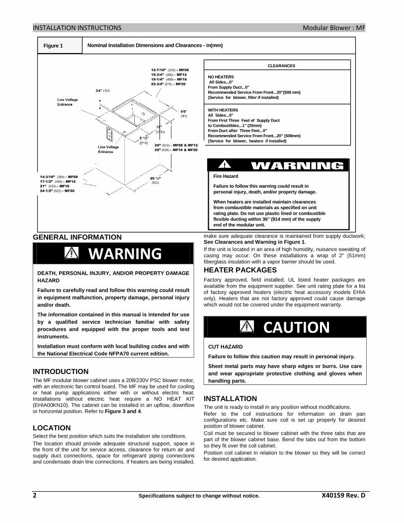
CLEARANCES
NO HEATERS All Sides...0" From Supply Duct...0"Recommended Service From Front...20"(508 mm)(Service for blower, filter if installed)
WITH HEATERSAll Sides...0" From First Three Feet of Supply Ductto Combustibles...1" (25mm)From Duct after Three Feet...0"Recommended Service From Front...20" (508mm)(Service for blower, heaters if installed)
Figure 1 Nominal Installation Dimensions and Clearances - in (mm)
Fire Hazard
Failure to follow this warning could result in personal injury, death, and/or property damage.
When heaters are installed maintain clearances from combustible materials as specified on unit rating plate. Do not use plastic lined or combustib le flexible ducting within 36'' (914 mm) of the supply end of the modular unit.
24"
20 1/2"
Low VoltageEntrance
Line VoltageEntrance
5/8"
8 1/2"
12"
3/4"
14a"'" (365) - 2 & 22 Ton17d" (454) - 3 & 32 Ton212" (546) - 4 Ton238" (587) - 5 Ton
15w" (400) - 2& 22 Ton)194" (489) - 3&32 Ton22d" (581) - 4 Ton242" (622) - 5 Ton
!
(521)
(609)
(305)
(216)
(19)
(15)
GENERAL INFORMATION
WARNING DEATH, PERSONAL INJURY, AND/OR PROPERTY DAMAGE HAZARD
Failure to carefully read and follow this warning c ould result in equipment malfunction, property damage, personal injury and/or death.
The information contained in this manual is intende d for use by a qualified service technician familiar with saf ety procedures and equipped with the proper tools and t est instruments.
Installation must conform with local building codes and with the National Electrical Code NFPA70 current edition .
INTRODUCTION The MF modular blower cabinet uses a 208/230V PSC blower motor, with an electronic fan control board. The MF may be used for cooling or heat pump applications either with or without electric heat. Installations without electric heat require a NO HEAT KIT (EHIA00KN10). The cabinet can be installed in an upflow, downflow or horizontal position. Refer to Figure 3 and 4 .
LOCATION Select the best position which suits the installation site conditions. The location should provide adequate structural support, space in the front of the unit for service access, clearance for return air and supply duct connections, space for refrigerant piping connections and condensate drain line connections. If heaters are being installed,
make sure adequate clearance is maintained from supply ductwork; See Clearances and Warning in Figure 1 . If the unit is located in an area of high humidity, nuisance sweating of casing may occur. On these installations a wrap of 2” (51mm) fiberglass insulation with a vapor barrier should be used.
HEATER PACKAGES Factory approved, field installed, UL listed heater packages are available from the equipment supplier. See unit rating plate for a list of factory approved heaters (electric heat accessory models EHIA only). Heaters that are not factory approved could cause damage which would not be covered under the equipment warranty.
CAUTION
CUT HAZARD
Failure to follow this caution may result in person al injury.
Sheet metal parts may have sharp edges or burrs. Us e care and wear appropriate protective clothing and gloves when handling parts.
INSTALLATION The unit is ready to install in any position without modifications. Refer to the coil instructions for information on drain pan configurations etc. Make sure coil is set up properly for desired position of blower cabinet. Coil must be secured to blower cabinet with the three tabs that are part of the blower cabinet base. Bend the tabs out from the bottom so they fit over the coil cabinet. Position coil cabinet in relation to the blower so they will be correct for desired application.
20 ½’’
(521)
12-7/16” (316) – MF08
15-3/4” (400) – MF12
19-1/4’’ (489) – MF16
22-3/4’’ (578) – MF20
24’’ (610) – MF08 & MF12
25’’ (635) – MF16 & MF20
14-3/16” (360) – MF08
17-1/2” (445) – MF12
21’’ (533) – MF16
24-1/2’’ (622) – MF20

INSTALLATION INSTRUCTIONS Modular Blower : MF
X40159 Rev. D Specifications subject to change without notice. 3
For upflow and horizontal applications apply foam seal strip around top of coil cabinet. For downflow application apply foam seal strip around bottom of coil cabinet. Set blower on top of coil cabinet so they are flush. Secure cabinets together using the three tabs on the bottom of the cabinet. Bend the tab out from the bottom so it fits over the coil cabinet. If no pilot holes are present, drill a hole as required for a screw.
Figure 3 Airflow Positions
SubbaseAccessory
DOWNFLOW INSTALLATIONS Refer to instructions with Subbase Kit.
NON-DUCTED RETURN AIR CLOSET INSTALLATION The cabinet can be installed in a closet with a false bottom to form a return air plenum, or mounted on an open platform inside the closet. Platform should be high enough to provide a free (open) area for adequate return airflow into the bottom of the cabinet. The open area can be on the front side or a combination of front and sides, providing there is clearance on the sides between cabinet and closet. Refer to ACCA Manual D for sizing and free area recommendations. NOTE: Local codes may limit application of systems without a ducted return to single story dwellings.
HORIZONTAL LEFT AND RIGHT INSTALLATIONS The modular blower cabinets can be installed in either downflow, horizontal left or horizontal right applications. When a coil cabinet is applied, refer to the coil installation manual for proper drain pan and airflow requirements. They must have the drain pan repositioned for right hand airflow. Refer to coil installation manual.
CAUTION
PROPERTY DAMAGE HAZARD
Failure to follow this caution may result in proper ty damage.
A field fabricated auxiliary drain pan, with a sepa rate drain is REQUIRED for all installations over a finished livi ng space or in any area that may be damaged by overflow from a restricted main drain pan. In some localities, loca l codes require an auxiliary drain pan for ANY horizontal i nstallation.
SUSPENDED CABINET INSTALLATION 1. The cabinet may be supported on a frame or shelf, or it may be
suspended.
Figure 2 Attach Coil to Blower Cabinet
Place seal on top of Coil Cabinet aroundperimeter
Panels removedfor clarity only
Bend Tabs (both sides and back) on Bottom of Blower Cabinet to Fit over Coil Cabinet
Low voltage wiring splice box
Figure 4 Airflow Positions

INSTALLATION INSTRUCTIONS Modular Blower : MF
4 Specifications subject to change without notice. X40159 Rev. D
2. Use metal strapping or threaded rod with angle iron supports under the auxiliary drain pan to suspend cabinet. These supports MUST run parallel with the length of the cabinet. Refer to Figure 5.
3. Ensure that there is adequate room to remove service and access panels after installing supporting brackets.
4. Place field installed vibration isolators in auxiliary drain pan to support cabinet.
DUCT CONNECTIONS Supply Duct Supply duct must be attached to the outside of flange on outlet end of unit. Flexible connectors may be used if desired. Maintain clearances from supply duct to combustibles when heaters are installed. Refer to Figure 1 and unit rating plate.
Return Duct Return duct should be attached to bottom of unit using sheet metal screws or other fasteners.
FILTER INSTALLATION Filters must be field supplied. A remote filter grille or other means must be provided. Refer to ACCA Manual D for remote filter sizing.
NOTE: If increased structural strength is needed in the horizontal position, use field supplied two connecting plates in place of the tabs on the bottom of the blower.
ELECTRICAL CONNECTIONS The MF modular blower utilizes an electronic fan control board which has a low voltage circuit protective fuse (5 AMP), and pigtail connections for thermostat hook up. The fan control also has a relay for blower operation, and built in 90 second blower-off time delay relay (TDR). To disable the TDR feature, snip the jumper wire JW1. Refer to Figure 6 . All electrical work MUST conform with the requirements of local codes and ordinances and the National Electrical Code NFPA 70 current edition. The low voltage transformer and the fan control are standard on all models and are prewired at the factory. Line voltage connections are made to the heater accessory or the lugs on the No Heat Kit.
WARNING ELECTRICAL SHOCK or UNIT DAMAGE HAZARD
Failure to follow this warning could result in pers onal injury, death, and/or property damage. If a disconnect switch is to be mounted on unit, se lect a location where drill and fasteners will not contact electrical refrigeration components.
OVERCURRENT PROTECTION The power supply wiring to the unit MUST be provided with overcurrent protection. Governing codes may require this to be fuses ONLY or circuit breakers. For blower cabinets without heaters, a 15 amp circuit may be used. Before proceeding with electrical connections, make certain that supply voltage, frequency, phase, and circuit ampacity are as specified on the unit rating plate. See unit wiring label for proper field high and low voltage wiring. Make all electrical connections in accordance with the NEC and any local codes or ordinances that may apply. Use copper wire only. The unit must have a separate branch electric circuit with a field-supplied disconnect switch located within sight from and readily accessible from the unit. NOTE: When a pull-out type disconnect is removed from the unit, only the Load side of the circuit is de-energized. The Line side remains live until the main (remote) disconnect is turned off.
Figure 5
Field-Fabricated Drain Pan
Supports MUST run parallel with blower cabinet
RefrigerantLines
DrainLines
Vibration Isolators
See Note Below
Horizontal Installation

INSTALLATION INSTRUCTIONS Modular Blower : MF
X40159 Rev. D Specifications subject to change without notice. 5
WARNING ELECTRICAL SHOCK or UNIT DAMAGE HAZARD
Failure to follow this warning could result in pers onal injury, death, and/or property damage.
Turn OFF electric power at fuse box or service pane l before making any electrical connections and ensure a prop er ground connection is made before connecting line vo ltage.
WARNING ELECTRICAL SHOCK HAZARD
Failure to follow this warning could result in pers onal injury or death. Turn OFF the main (remote) disconnect device before working on incoming (field) wiring. Incoming (field ) wiring on the line side of the disconnect found in the modula r blower unit remains live, even when the pull-out is remove d. Service and maintenance to incoming (field) wiring cannot b e performed until the main disconnect switch (remote to the unit) is turned off.
MF units installed without electric heat require the use of a factory-authorized No Heat Kit (accessory part number EHIA00KN10). This kit provides the electrical connections necessary to supply the unit with 208/230V power when electric heat is not present. For units without electric heat: 1. Locate adapter and filler plates with screws inside package. If
necessary, adjust plates to allow for installation of No Heat Kit required inside cabinet. Refer to Figure 7.
2. Secure No Heat Kit accessory with four (4) screws. 3. Connect the 9-pin plug from No Heat Kit wiring into the
receptacle that attaches to fan control board. 4. Connect ground wire to unit ground lug. 5. Connect 208/230V power lead from field disconnect to No Heat
Kit. For units with electric heat, see Electric Heater Installation Instructions and blower airflow requirements. NOTE: Transformer is factory-wired for 230V operation. For 208V applications the transformer must be rewired to the 208V tap. Refer to unit wiring label.
GROUNDING CONNECTION Use a copper conductor(s) from the ground lug on the No Heat Kit or ground lugs on the electric heater to a grounded connection in the electric service panel or a properly installed grounding rod.
Low Voltage Control Connections Wire low-voltage in accordance with wiring label on the blower (also refer to Figures 8 - 12 . Use 18 AWG color-coded, insulated (35°C minimum) wire to make the low-voltage connections between: thermostat, indoor equipment, and outdoor equipment. If thermostat is located more than 100 feet (31m) from the unit (as measured along the low voltage wire), use 16 AWG color-coded, insulated (35°C minimum) wire. All wiring must be NEC Class 1 and must be separated from incoming power leads. Refer to outdoor unit wiring instructions for additional wiring recommendations. Field supplied low-voltage wiring should be field connected inside control splice box area (secure with wire nuts), and strain relief bushing or rubber grommet to seal cabinet opening.
Electrical ControlsFigure 7
Adapter Plate
Filler Plate
GroundConnection
No Heat Kit
Low VoltageConnections
Control Splice Box

INSTALLATION INSTRUCTIONS Modular Blower : MF
6 Specifications subject to change without notice. X40159 Rev. D
Supply Circuit Recommended
Supply Wire 75°C copper
Ground Wire
Table 1
Volts Phase Hertz
Supply Circuit No.
H.P. Max. Motor Amps
MCA Branch Circuit AMP
Max Over- current Protection Devise (Amps)
# of Wires
Min Size
Max. Ft.(m) Length
# of Wires
Min Size
208 MF08*
230
1 60 Single 1/3 2.5 3.1 15 2 14 105 (32) 1 14
208 MF12*
230
1 60 Single 1/2 2.9 3.6 15 2 14 105 (32) 1 14
208 MF16*
230
1 60 Single 1/2 2.9 3.6 15 2 14 105 (32) 1 14
208 MF20*
230
1 60 Single 3/4 6.0 7.5 15 2 14 90 (27) 1 14
Figure 8 Wiring Layout Air Conditioning Unit (Cooling Only)
R
G
W
Y
THERMOSTAT
RED
GRY
WHT
PINK
VIO
BRN
WHT
R
G
W 2
W 3
E
C
C
Y
AIR COND.
Figure 9 Wiring Layout Air Conditioning Unit (Cooling and Single-Stage Heat)
R
G
W
Y
THERMOSTAT
R
G
W2
W3
E
C
C
Y
AIR COND.
RED
GRY
PINK
VIO
BRN
WHTWHT
Figure 10 Wiring Layout Heat Pump Unit (Cooling and Single-Stage Heat with No Outdoor
Thermostat)
R
G
C
E
L
O
Y
THERMOSTAT
RR
C
O
Y
G
C
W 2
W 2
W 2
W 3
E
HEAT PUMP(CONTROL)
RED
GRY
BRN
WHT
PINK
VIO

INSTALLATION INSTRUCTIONS Modular Blower : MF
X40159 Rev. D Specifications subject to change without notice. 7
Figure 11 Wiring Layout Heat Pump Unit (Cooling and Two-Stage Heat with One Outdoor
Thermostat)
R
G
C
E
L
O
Y
THERMOSTAT
RR
C
O
Y
G
C
W 2
W 2
W 2
W 3
E
ODTS
HEAT PUMP(CONTROL)
RED
GRY
BRN
WHTVIO
PINK
Figure 12 Wiring Layout Heat Pump Unit (Cooling and Two-Stage Heat with Two Outdoor
Thermostats)
R
G
C
E
L
O
Y
THERMOSTAT
RR
C
O
Y
G
C
W 2
W 2
W 2
W 3
E
ODTS
HEAT PUMP(CONTROL)
RED
GRY
BRN
WHTVIO
PINK
ODTS
CHANGING MOTOR SPEED To change the blower speed, disconnect the black wire at the blower motor terminal block and reconnect at the desired blower speed tap (refer to Table 4 ).
HEATER STAGING The modular controls are factory circuited for single-stage electric heat operation. Refer to Table 2 for available heaters and Table 3 for unit airflow based without a coil, filter, or electric heat applied.
When two-stage electric heat is desired (refer to Table 2 - Heat Strip Staging ), separate out the pink W3 wire from W2 & E connections. Refer to Table 2-2 and wiring diagram Figure 11 . W3 can be separated and controlled by the indoor wall thermostat (if multi-stage capable), or by an outdoor thermostat (ODTS). Refer to ODTS kit instruction for proper wiring. When three-stage electric heat is desired, cut the W2 wire nut off and discard. Strip W2, W3, and E. Refer to Table 2-3 , and wiring diagram Figures 12 . Connect according to the thermostat kit instructions or ODTS kit instructions for proper wiring.
Table 2 Heat Strip Staging
2-1 2-2 2-3
Single-Stage
Operation
(no staging - all
electric heat
together)
Two-Stage
Capable
Three-Stage
Capable
(with ODTS
only)
EHIA05KB / KN EHIA15KB EHIA25KB10
EHIA07KB / KN EHIA20KB
EHIA10KB / KN EHIA25KB
EHIA15KB
EHIA20KB
Single-
Phase
EHIA25KB
EHIA10HB EHIA10HB EHIA20HB
EHIA15HB EHIA15HB EHIA25HB
EHIA20HB EHIA20HB
Three-
Phase
EHIA25HB EHIA25HB KB is single-phase with circuit breaker KN is single-phase with terminal block (no-breaker) HB is three-phase with circuit breaker
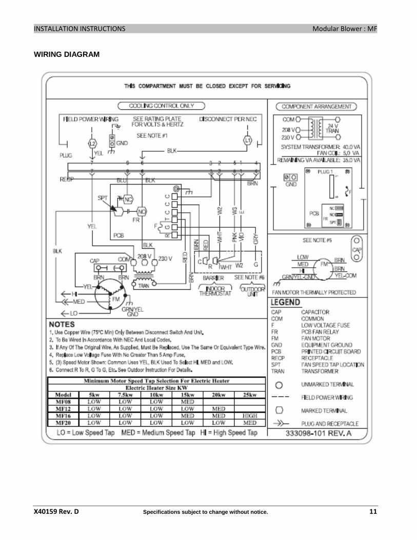
Table 3 Minimum Motor Speed Tap Selection For
Electric Heater
Electric Heater SIZE kW
Model 5 kW 7.5 kW 10 kW 15 kW 20 kW 25 kW
MF08 LOW LOW LOW MED -- --
MF12 LOW LOW LOW LOW MED --
MF16 LOW LOW LOW MED MED HIGH
MF20 LOW LOW LOW LOW LOW MED
LOW = low speed tap selection
MED = medium speed tap selection
HIGH - high speed tap selection
AIR FLOW CHECK For proper system operation, the air flow through the indoor coil should be between 350 and 450 cfm per ton of cooling capacity. The air flow through the unit can be determined by measuring the external static pressure to the unit and selecting the motor speed tap that will most closely provide the required air flow. 1. Set up to measure external static pressure at the supply and
return duct connections. Refer to Figure 13 . 2. Drill holes in the ducts for pressure taps, pilot tubes, or other
accurate pressure sensing devices. 3. Connect these taps to a level inclined manometer or draft
gauge. 4. Ensure the coil and filter are clean, and all the registers are
open. 5. Determine the external static pressure with the blower
operating.

INSTALLATION INSTRUCTIONS Modular Blower : MF
8 Specifications subject to change without notice. X40159 Rev. D
6. Refer to the Air Flow Data, Table 4 , to find the speed setting that will most closely provide the required air flow for the system.
7. Refer to Motor Speeds and Airflow in these instructions if the speed is to be changed.
8. Recheck the external static pressure with the new setting, and confirm speed switch selection.
Figure 13 Static Pressure Check
Supply
Indoor Section
InclineManometer
Return
TEMPERATURE RISE CHECK Temperature rise is the difference between the supply and return air temperatures.
NOTE: The temperature rise can be adjusted by changing the heating speed tap at the unit’s blower terminal block. Refer to the unit’s Installation Instructions for airflow information.
A temperature rise greater than 60 °F (33.3°C) is not recommended. 1. To check the temperature rise through the unit, place
thermometers in the supply and return air ducts as close to the unit as possible,avoiding direct radiant heat from the heater elements.
2. Open ALL registers and duct dampers.
3. Set thermostat Heat-Cool selector to HEAT.
4. Set the thermostat temperature setting as high as it will go.
5. Turn electric power ON.
6. Operate unit AT LEAST 5 minutes, then check temperature rise.
NOTE: The maximum outlet air temperature for all models is 200°F (93.3°C). 7. Set thermostat to normal temperature setting.
8. Be sure to seal all holes in ducts if any were created during this process.
Airflow Based on no coil, no filter, no electric heat. Deduct heater static shown in heater static table.
Deduct coil static, See Coil Specification Sheet. Deduct .20 in wc (50 Pa) for Downflow Subbase Kit.
Table 4 Airflow is blower only, no coil attached MF08 In wc
SPEED VOLTS 0.20 0.30 0.40 0.50 0.60 0.70 0.80 230v 1029 1020 1007 985 960 915 862 Low 208v 872 860 845 825 797 765 721 230v 1286 1270 1254 1220 1180 1125 1058 Med 208v 1113 1105 1091 1070 1042 1000 947 230v 1500 1470 1432 1380 1315 1250 1168 High 208v 1317 1305 1286 1255 1220 1170 1008
MF012 In wc SPEED VOLTS 0.20 0.30 0.40 0.50 0.60 0.70 0.80
230v 973 975 979 979 973 955 931 Low 208v 811 815 816 810 797 780 749 230v 1284 1295 1301 1305 1302 1280 1246 Med 208v 1084 1084 1084 1090 1089 1065 1030 230v 1663 1670 1671 1655 1631 1585 1519 High 208v 1383 1385 1390 1390 1383 1365 1328
MF16 In wc SPEED VOLTS 0.20 0.30 0.40 0.50 0.60 0.70 0.80
230v 1020 1015 1009 1002 991 975 950 Low 208v 858 845 830 815 801 780 749 230v 1379 1385 1386 1379 1364 1343 1309 Med 208v 1156 1154 1149 1144 1134 1120 1098 230v 1776 1782 1783 1765 1736 1698 1643 High 208v 1496 1496 1496 1495 1495 1470 1433
MF20 In wc SPEED VOLTS 0.20 0.30 0.40 0.50 0.60 0.70 0.80
230v 1492 1495 1492 1475 1451 1395 1308 Low 208v 1246 1245 1238 1225 1203 1175 1125 230v 1969 1955 1935 1890 1818 1700 1570 Med 208v 1641 1640 1633 1615 1584 1510 1406 230v 2696 2600 2492 2350 2192 2020 1844 High 208v 2417 2355 2287 2200 2092 1940 1774
* THE MAXIMUM EXTERNAL STATIC PRESSURE IS 0.8’’ W.C ., WITHOUT COOLING COIL. DEDUCT STATIC PRESSURE OF COIL FOR MAXIMUM STATIC PRESSURE.

INSTALLATION INSTRUCTIONS Modular Blower : MF
X40159 Rev. D Specifications subject to change without notice. 9
Table 5 - ELECTRIC HEATHER STATIC PRESSURE DROP Single-Phase
EHIA 05
EHIA 07
EHIA 10
EHIA 15
EHIA 20
EHIA 25 CFM
In wc 600 0.01 0.01 0.01 – – – 700 0.01 0.01 0.01 – – – 800 0.01 0.01 0.01 0.01 – – 900 0.01 0.01 0.01 0.01 – – 1000 0.01 0.01 0.01 0.01 0.02 – 1100 0.01 0.01 0.01 0.02 0.02 – 1200 0.01 0.01 0.01 0.02 0.02 – 1300 0.01 0.02 0.02 0.02 0.02 – 1400 0.01 0.02 0.02 0.02 0.03 0.03 1500 0.01 0.02 0.02 0.02 0.03 0.04 1600 0.01 0.02 0.02 0.03 0.03 0.04
1700 0.01 0.02 0.02 0.03 0.03 0.04
1800 0.01 0.02 0.02 0.03 0.04 0.04
1900 0.01 0.02 0.02 0.03 0.04 0.05
2000 0.01 0.02 0.02 0.03 0.04 0.05
ACCESSORIES
ELECTRIC AIR CLEANER
The Electronic Air Cleaner may be connected to MF as shown in Figure 14 . This method requires a field supplied transformer. See Electronic Air Cleaner literature for kit requirements.
HUMIDIFIER
Connect humidifier and humidistat to modular blower unit as shown in Figures 15 and 16 .
Three-Phase EHIA
10 EHIA
15 EHIA
20 EHIA
25 CFM N/A N/A In wc
600 0.01 – – – 700 0.01 – – – 800 0.01 0.01 – – 900 0.01 0.01 – – 1000 0.01 0.01 0.02 – 1100 0.01 0.02 0.02 – 1200 0.01 0.02 0.02 – 1300 0.02 0.02 0.02 – 1400 0.02 0.02 0.03 0.03 1500 0.02 0.02 0.03 0.04 1600 0.02 0.03 0.03 0.04
1700 0.02 0.03 0.03 0.04
1800 0.02 0.03 0.04 0.04
1900 0.02 0.03 0.04 0.05
2000 0.02 0.03 0.04 0.05

INSTALLATION INSTRUCTIONS Modular Blower : MF
10 Specifications subject to change without notice. X40159 Rev. D
SEQUENCE OF OPERATION
A. CONTINUOUS FAN
Thermostat closes R to G. G energizes fan relay on FAN CONTROL BOARD which completes the high voltage circuit to indoor blower motor. When G is de-energized, there is a built in 90 second blower-off time delay relay (TDR). To disable the TDR feature, snip the jumper wire JW1.
B. COOLING MODE
Air Conditioner Only:
Thermostat energizes R to G and Y. G energizes fan relay on fan control board which completes high-voltage circuit to indoor blower motor. Y energizes the 24 low-voltage contactor in condensing unit. When call is satisfied, Y drops out and there is a 90 second blower TDR before fan relay opens.
Heat Pump:
Same as above - except thermostat will also energize O for reversing valve operation in cooling mode. O will typically remain energized by the thermostat (after cooling call is satisfied), or until the mode is changed to heating.
C. HEAT PUMP
Cooling Mode:
Thermostat energizes R to G, Y and O. G energizes indoor an relay on fan control board which completes high-voltage circuit to indoor
blower motor. Y energizes the outdoor 24V low-voltage circuit in heat pump to energize compressor. O energizes reversing valve in cooling mode and typically remains energized until the mode is changed to heating. When thermostat cooling call is satisfied. Y drops out. O remains energized, and there is a 90 second TDR before indoor fan relay opens.
Heating Mode:
Thermostat energizes R to G and Y only (no O signal in heating). G energizes indoor fan relay on fan control board which completes high-voltage circuit to indoor blower motor. Y energizes the outdoor 24V low-voltage circuit in heat pump to energize compressor. The reversing valve is not energized in heating unless a defrost cycle should occur. When call is satisfied, Y drops out and there is a 90 second TDR before indoor fan relay opens.
D. HEAT PUMP HEATING WITH AUXILIARY ELECTRIC HEAT
Cooling Mode:
Same operation as above in Heat Pump Cooling Mode.
Heating Mode:
Same operation as above in Heat Pump Heating Mode with the addition of W. Thermostat energizes R to G, Y, and W. W energizes electric heat relay(s) which completes circuit to heater element(s). When W is de-energized, electric heat relay(s) open, turning off heater elements. The White wire in pigtail connects W2, W3, and E together. This may be separated for heater staging when available, see electric heat kit for more information.
E. ELECTRIC HEAT OR EMERGENCY HEAT MODE Thermostat closes R to W. W energizes electric heat relay(s) which completes circuit to heater elements(s). Blower motor is energized through N.C. (normally closed) contacts on fan relay. When W is de-energized, electric heat relay(s) opens.
CARE AND MAINTENANCE The system should be regularly inspected by a qualified service technician. Consult the servicing dealer for recommended frequency. Between visits, the only consumer service recommended or required is air filter maintenance and condensate drain operation.
AIR FILTER Inspect air filters at least monthly and replace or clean as required. Disposable type filters should be replaced. Reusable type filters may be cleaned by soaking in mild detergent and rinsing with cold water. The frequency of cleaning depends upon the hours of operation and the local atmospheric conditions. Install filters with the arrows on the side pointing in the direction of air flow. Clean filters keep unit efficiency high.
LUBRICATION The bearings of the blower motor are permanently lubricated.
CONDENSATE DRAINS During the cooling season check the condensate drain lines to be sure that condensate is flowing from the primary drain but not from the secondary drain. If condensate ever flows from the secondary drain, the unit should be promptly shut off and the condensate pan and drains cleaned to insure a free flowing primary drain.
INSTALLATION INSTRUCTIONS Modular Blower : MF
X40159 Rev. D Specifications subject to change without notice. 11
WIRING DIAGRAM
INSTALLATION INSTRUCTIONS Modular Blower : MF
12 Specifications subject to change without notice. X40159 Rev. D
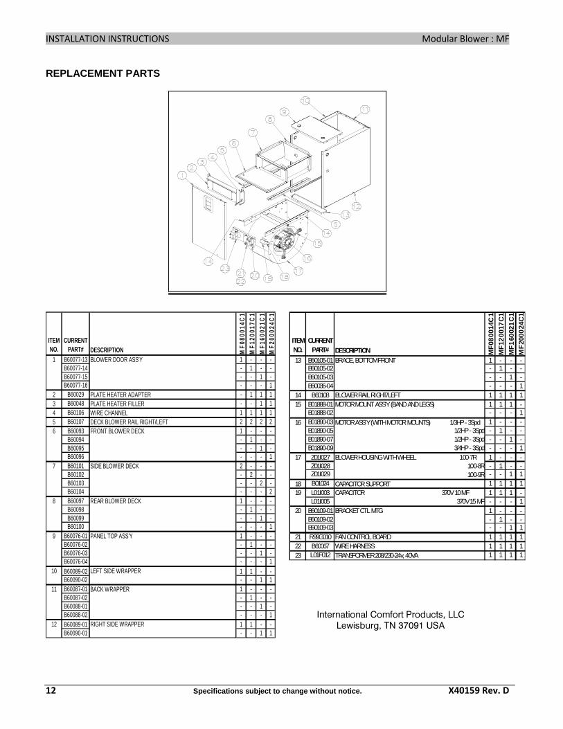
REPLACEMENT PARTS
ITEM NO.
CURRENTPART# DESCRIPTION M
F08
0014
C1
MF
1200
17C
1M
F16
0021
C1
MF
2000
24C
1
B60077-13 1 - - -B60077-14 - 1 - -B60077-15 - - 1 -B60077-16 - - - 1
2 B60029 PLATE HEATER ADAPTER - 1 1 13 B60048 PLATE HEATER FILLER - - 1 14 B60106 WIRE CHANNEL 1 1 1 15 B60107 DECK BLOWER RAIL RIGHT/LEFT 2 2 2 2
B60093 1 - - -B60094 - 1 - -B60095 - - 1 -B60096 - - - 1B60101 2 - - -B60102 - 2 - -B60103 - - 2 -B60104 - - - 2B60097 1 - - -B60098 - 1 - -B60099 - - 1 -B60100 - - - 1
B60076-01 1 - - -B60076-02 - 1 - -B60076-03 - - 1 -B60076-04 - - - 1B60089-02 1 1 - -B60090-02 - - 1 1B60087-01 1 - - -B60087-02 - 1 - -B60088-01 - - 1 -B60088-02 - - - 1B60089-01 1 1 - -B60090-01 - - 1 1
11 BACK WRAPPER
12 RIGHT SIDE WRAPPER
9 PANEL TOP ASS'Y
10 LEFT SIDE WRAPPER
7 SIDE BLOWER DECK
8 REAR BLOWER DECK
1 BLOWER DOOR ASS'Y
6 FRONT BLOWER DECK
International Comfort Products, LLC
Lewisburg, TN 37091 USA
ITEM NO.
CURRENTPART# DESCRIPTION M
F08
0014
C1
MF
1200
17C
1M
F1
6002
1C
1M
F20
0024
C1
B60105-01 1 - - -B60105-02 - 1 - -B60105-03 - - 1 -B60036-04 - - - 1
14 B60108 BLOWER RAIL RIGHT/LEFT 1 1 1 1B01888-01 1 1 1 -B01888-02 - - - 1B01890-03 MOTOR ASS'Y (WITH MOTOR MOUNTS) 1/3HP - 3Spd 1 - - -B01890-05 1/2HP - 3Spd - 1 - -B01890-07 1/2HP - 3Spd - - 1 -B01890-09 3/4HP - 3Spd - - - 1Z01I027 BLOWER HOUSING WITH WHEEL 100-7R 1 - - -Z01I028 100-8R - 1 - -Z01I029 100-9R - - 1 1
18 B01024 CAPACITOR SUPPORT 1 1 1 1L01I003 CAPACITOR 370V 10 MF 1 1 1 -L01I005 370V 15 MF - - - 1
B60109-01 BRACKET CTL MTG 1 - - -B60109-02 - 1 - -B60109-03 - - 1 1
21 R99G010 FAN CONTROL BOARD 1 1 1 122 B60067 WIRE HARNESS 1 1 1 123 L01F012 TRANSFORMER 208/230-24v, 40VA 1 1 1 1
13 BRACE, BOTTOM FRONT
15 MOTOR MOUNT ASS'Y (BAND AND LEGS)
16
17
19
20