INSTALLATION INSTRUCTIONS - Inglenook Energy INSTRUCTIONS A French manual is available upon request....
36
This appliance may be installed in an aftermarket per- manently located, manufactured home (USA only) or mobile home, where not prohibited by local codes. This appliance is only for use with the type of gas indicated on the rating plate. This appliance is not convertible for use with other gases, unless a certified kit is used. In the Commonwealth of Massachusetts: • Installation must be performed by a licensed plumber or gas fitter; • See Table of Contents for location of additional Com- monwealth of Massachusetts requirements. INSTALLATION INSTRUCTIONS A French manual is available upon request. Order P/N 506223-03 Ce manuel d’installation est disponible en francais, simplement en faire la demande. Numéro de la pièce 506223-03. MODELS INSTALLER: Leave this manual with the appliance. CONSUMER: Retain this manual for future reference. OTL Report No. 6-F-57-5 US Portland MLDVT-30NE MLDVT-35NE MLDVT-40NE MLDVT-45NE Millivolt Models Electronic Models MLDVT-30NM MLDVT-30PM MLDVT-35NM MLDVT-35PM MLDVT-40NM MLDVT-40PM MLDVT-45NM MLDVT-45PM INSTALLATEUR: Laissez cette notice avec l'appareil. CONSOMMATEUR: Conservez cette notice pour con- sultation ultérieure. WARNING: IF THE INFORMATION IN THIS MANUAL IS NOT FOLLOWED EXACTLY, A FIRE OR EXPLO- SION MAY RESULT CAUSING PROPERTY DAMAGE, PERSONAL INJURY OR LOSS OF LIFE. DIRECT VENT MLDVT-30/35/40/45 SERIES Do not store or use gasoline or other flammable vapors or liquids in the vicinity of this or any other appliance. WHAT TO DO IF YOU SMELL GAS: • Do not light any appliance. • Do not touch any electrical switch; do not use any phone in your building. • Immediately call your gas supplier from a neighbor’s phone. Follow your gas supplier's instructions. • If your gas supplier cannot be reached, call the fire department. Installation and service must be performed by a qualified installer, service agency or the gas supplier. AVERTISSEMENT: ASSUREZ-VOUS DE BIEN SUIVRE LES INSTRUCTIONS DONNÉES DANS CETTE NOTICE POUR RÉDUIRE AU MINIMUM LE RISQUE D'INCENDIE D'EXPLOSION OU POUR ÉVITER TOUT DOMMAGE MATÉRIEL, TOUTE BLESSURE OU LA MORT. Ne pas entreposer ni utiliser d'essence ni d'autre vapeurs ou liquides inflammables dans le voisinage de cet appareil ou de tout autre appareil. QUE FAIRE SI VOUS SENTEZ UNE ODEUR DE GAZ: • Ne pas tenter d'allumer d'appareil. • Ne touchez à aucun interrupteur. Ne pas vous servir des téléphones se trouvant dans le báti- ment où vous vous trouvez. • Appelez immédiatement votre fournisseur de gaz depuis un voisin. Suivez les instructions du fournisseur. • Si vous ne pouvez rejoindre le fournisseur de gaz, appelez le service des incendies. L'installation et l'entretien doivent être assurés par un installeur ou un service d'entretien qualifié ou par le fournisseur de gaz. VENTED GAS FIREPLACE HEATERS - DIRECT VENT MODELS P/N 50605-02 REV. A 06/2009
Transcript of INSTALLATION INSTRUCTIONS - Inglenook Energy INSTRUCTIONS A French manual is available upon request....

�
This appliance may be installed in an aftermarket per-manently located, manufactured home (USA only) or mobile home, where not prohibited by local codes. This appliance is only for use with the type of gas indicated on the rating plate. This appliance is not convertible for use with other gases, unless a certified kit is used.
In the Commonwealth of Massachusetts:• Installation must be performed by a licensed plumber or
gas fitter;• See Table of Contents for location of additional Com-
monwealth of Massachusetts requirements.
INSTALLATIONINSTRUCTIONS
A French manual is available upon request. Order P/N 506223-03
Ce manuel d’installation est disponible en francais, simplement en faire la demande. Numéro de la pièce 506223-03.
MODELS
INSTALLER: Leave this manual with the appliance.CONSUMER: Retain this manual for future reference.
OTL Report No. ��6-F-57-5US
Portland
MLDVT-30NEMLDVT-35NEMLDVT-40NEMLDVT-45NE
Millivolt Models Electronic ModelsMLDVT-30NMMLDVT-30PMMLDVT-35NMMLDVT-35PMMLDVT-40NMMLDVT-40PMMLDVT-45NMMLDVT-45PM
INSTALLATEUR: Laissez cette notice avec l'appareil.CONSOMMATEUR: Conservez cette notice pour con-sultation ultérieure.
WARNING: IF THE INFORMATION IN THIS MANUAL IS NOT FOLLOWED EXACTLY, A FIRE OR EXPLO-SION MAY RESULT CAUSING PROPERTY DAMAGE, PERSONAL INJURY OR LOSS OF LIFE.
DIRECT VENTMLDVT-30/35/40/45 SERIES
Do not store or use gasoline or other flammable vapors or liquids in the vicinity of this or any other appliance.
WHAT TO DO IF YOU SMELL GAS:
• Do not light any appliance.• Do not touch any electrical switch; do not use any phone in your building.• Immediately call your gas supplier from a neighbor’s phone. Follow your gas supplier's instructions.• If your gas supplier cannot be reached, call the fire department.
Installation and service must be performed by a qualified installer, service agency or the gas supplier.
AVERTISSEMENT: ASSUREZ-VOUS DE BIEN SUIVRE LES INSTRUCTIONS DONNÉES DANS CETTE NOTICE POUR RÉDUIRE AU MINIMUM LE RISQUE D'INCENDIE D'EXPLOSION OU POUR ÉVITER TOUT DOMMAGE MATÉRIEL, TOUTE BLESSURE OU LA MORT.
Ne pas entreposer ni utiliser d'essence ni d'autre vapeurs ou liquides inflammables dans le voisinage de cet appareil ou de tout autre appareil.
QUE FAIRE SI VOUS SENTEZ UNE ODEUR DE GAZ:
• Ne pas tenter d'allumer d'appareil.• Ne touchez à aucun interrupteur. Ne pas vous
servir des téléphones se trouvant dans le báti-ment où vous vous trouvez.
• Appelez immédiatement votre fournisseur de gaz depuis un voisin. Suivez les instructions du fournisseur.
• Si vous ne pouvez rejoindre le fournisseur de gaz, appelez le service des incendies.
L'installation et l'entretien doivent être assurés par un installeur ou un service d'entretien qualifié ou par le fournisseur de gaz.
VENTED GAS FIREPLACE HEATERS - DIRECT VENT MODELSP/N 5060�5-02 REV. A 06/2009

2 NOTE:DIAGRAMS&ILLUSTRATIONSARENOTTOSCALE.
TABLE OF CONTENTS
Packaging.........................................Page 2Introduction......................................Page 2GeneralInformation..........................Page 2RequirementsfortheCommonwealthofMassachusetts.Page 4NewYorkCityApproval.....................Page 4ColdClimateInsulation.....................Page 4Location............................................Page 4ManufacturedHomeRequirements..Page 5VentTerminationClearances............Page 5ApplianceandVentClearances.........Page 7DetailedInstallationSteps.................Page 8TypicalInstallationSequence...........Page 8Step1.Framing.................................Page 8Step2.RoutingGasLine..................Page 8FireplaceSpecifications.....................Page 9Step3.InstalltheVentingSystem....Page 11VerticalTerminationSystems............Page 12VentSectionLengthChart................Page 12VerticalVentTablesandFigures........Page 14HorizontalTerminationSystem.........Page 16HorizontalVentTablesandFigures...Page 19VentingUsingFlexibleVentPipe.......Page 22Step4. FieldWiring.........................Page 23Step5. OptionalBlowerKitWiring..Page 24Step6. ConnectingGasLine...........Page 24Step7. CheckingUnitOperation.....Page 25Step8. InstallingLogs...................Page 26Step9. InstallingGlassDoor..........Page 30Step10.BurnerAdjustments............Page 30Step11.HoodInstallation.................Page 32FinishingRequirements....................Page 32InstallationAccessories....................Page 32Gas Conversion Kits .................. Page 34
PACKAGING
Theassembledventedgasfireplaceheaterispackagedwith:
1-Onelogsetlocatedinfireboxarea.2-Oneenvelopecontainingtheliteraturepack-
agewhichconsistsofthecareandopera-tionsmanual,installationinstructions,andwarranty;envelopeislocatedinthecontrolcompartment.
3-OneventrestrictortobeappliedasshownonPage �� ;restrictoristapedtotheenvelope.
4-Onehoodlocatedbehindthedoorassembly.5-Onebagofdecorativevolcanicstonelocated
inthecontrolcompartment.6-Onebagofglowingemberslocatedinthe
controlcompartment.
INTRODUCTION
The Millivolt appliances have a millivolt gascontrolvalvewithpiezoignitionsystemwhichprovidessafe,efficientoperation.Ifanyoptionalaccessories that will require electrical poweraretobeinstalled,theelectricalpowermustbeprovidedatthetimeofapplianceinstallation.
The Electronic appliances have a batterybackedupelectronicintermittentpilotignitionsystemwhichprovidessafe,efficientopera-tion.Noexternalelectricalpowerisrequiredtooperatetheseappliances.
These vented gas fireplace heaters are sealedcombustion, air circulating gas fireplaces de-signedforresidentialapplications.
Approved Vent Components-Thesefireplacesaredesigned, testedand listed foroperationandinstallationwith,thefollowingventcom-ponentsonly:• Secure Vent™DirectVentSystemCompo-
nents,• Secure Flex™ Flexible Vent Components
manufactured by Security Chimneys Inter-nationaland
• Z-FLEX™ModelGAVentingSystemslistedtoUL1777andULCS635manufacturedbyFlexmasterCanadaLimited.
Theseapprovedventsystemcomponentsarelabeledforidentification.DONOTuseanyothermanufacturer’s vent components with theseappliances.Useonlythecorrectsizeventing(4-1/2"innerand7-1/2"outer).
DO NOT ATTEMPT TO ALTER OR MODIFY THE CONSTRUCTION OF THE APPLIANCE OR ITS COMPONENTS. ANY MODIFICATION OR ALTERATION MAY VOID THE WARRANTY, CER-TIFICATION AND LISTINGS OF THIS UNIT.
These appliances comply with National SafetyStandardsandaretestedandlistedbyOMNI-TestLaboratories,Inc.(ReportNo.116-F-57-5)toANSIZ21.88(inCanada,CSA-2.33),andCAN/CGA-2.17-M91inbothUSAandCanada,asventedgasfireplaceheaters.
Both millivolt and electronic versions of these appliances are listed by OMNI-Test Laboratories for installation in bedrooms and Manufactured Homes.
Misc. Codes / Standards - Installation must conform to local codes. Intheabsenceof localcodes, installationmustcomply with the current National Fuel GasCode, ANSI Z223.1. (In Canada, the currentCAN/CSA-B149.1installationcode).
Theappliance,wheninstalled,mustbeelectri-callygroundedandwiredinaccordancewithlocalcodesor,intheabsenceoflocalcodes,withtheNationalElectricalCode,ANSI/NFPA70-latest edition, or the Canadian ElectricalCode,CSAC22.1-latestedition.
GENERAL INFORMATION
Note: Installation and repair should be per-formed by a qualified service person. The appliance should be inspected annually by a qualified professional service technician. More frequent inspections and cleanings may be required due to excessive lint from carpet-ing, bedding material, etc. It is important that the control compartment, burners and circulating air passage ways of the appliance be kept clean.
S'assurer que le brùleur et le compartiment des commandes sont propres. Voir les instructions d'installation et d'utilisation qui accompagnent l'appareil.
Thismanualispartofasetoftwosupportingthisproduct.Refertomanual506017-01forCareandOperationinformation.
Please read and understand these instructions before beginning your
installation.
WARNING: IMPROPER INSTALLA-TION, ADJUSTMENT, ALTERATION, SERVICE OR MAINTENANCE CAN CAUSE INJURY OR PROPERTY DAMAGE. FOR ASSISTANCE OR ADDITIONAL INFORMATION CON-SULT A QUALIFIED INSTALLER, SERVICE AGENCY OR THE GAS SUPPLIER.
WARNING: FAILURE TO COMPLY WITH THESE INSTALLATION INSTRUCTIONS WILL RESULT IN AN IMPROPERLY INSTALLED AND OPERATING APPLI-ANCE, VOIDING ITS WARRANTY. ANY CHANGE TO THIS APPLIANCE AND/OR ITS OPERATING CONTROLS IS DANGEROUS.

3NOTE:DIAGRAMS&ILLUSTRATIONSARENOTTOSCALE.
Inlet Gas Supply Pressure (all models)
Fuel # Minimum Maximum
Natural Gas 4.5" WC(�.�2 kPa)
�0.5" WC(2.6� kPa)
Propane ��.0" WC(2.74 kPa)
�3.0" WC(3.23 kPa)
Table 3
Gas Pressure - All ModelsTables 3 and 4 showtheappliances'gaspressurerequirements:
Testgaugeconnectionsareprovidedon thefrontofthemillivoltandelectronicgascontrolvalve(identifiedINforthe inletandOUTforthemanifoldside).Thecontrolvalveshavea3/8"(10mm)NPTthreadinletandoutletsideofthevalve.
Gas Valve Diagrams
SeeFigure 1forMillivoltmodelsandFigure 2 ForElectronicModels.
Theseappliancesmustnotbeconnectedtoachimneyorflueservingaseparatesolidfuelburningappliance.
Orifice Sizes - Sea Level to High Altitude(All Models)
Theseappliancesaretestedandapprovedforinstallationatelevationsof0-4500feet(0-1372meters) above sea level using the standardburner orifice sizes (marked with an "*" inTable 5 ). For elevations above 4500 feet,contactyourgassupplierorqualifiedservicetechnician.
Installtheapplianceaccordingtotheregulationsofthelocalauthoritieshavingjurisdictionand,intheUSA,theNationalFuelGasCodeNFPA54/ANSIZ223.1-latesteditionor,inCanada,theCAN/CSA-B149.1-latestedition.
Manifold Gas Supply Pressure(all models)
Fuel # Low High
Natural Gas
(Lo) 2.2" WC(0.55 kPa)
(Hi) 3.5" WC(0.87 kPa)
Propane (Lo) 6.3" WC(�.57 kPa)
(Hi) �0.0" WC(2.49 kPa)
Table 4Burner Orifice Sizes
Elevation 0-4500 feet ( 0-�372 meters)
ModelSeries
Nat.Gasdrill size (inches)
Propanedrill size (inches)
MLDVT-30 #50 (0.070")*H4873•
#59 (0.04�")*H7838
MLDVT-35 #49 (0.073")*2�L82•
0.045"*75L�0•
MLDVT-40 #43 (0.089")*99K75•
#55 (0.052")*�9L52•
MLDVT-45 0.090"*37L70•
#54 (0.055")*99K79•
Table 5
Theseappliancesmustbeisolatedfromthegassupplypipingsystem(by closing their individual manual shut-off valve)duringanypressure testingof thegas supplypipingsystemat testpressuresequal toor less than 1/2psig(3.5kPa).
These appliances and their individualshut-offvalvesmust be disconnectedfromthegassupplypipingsystemduringanypressuretestingofthatsystematpressuresgreater than1/2psig(3.5kPa).
Propanetanksareatpressuresthatwillcausedamagetovalvecomponents.Verifythatthetankshavestepdownregulatorstoreducethepressuretosafelevels.
Donotusetheseappliancesifanyparthasbeenunderwater.Immediatelycallaqualified,profes-sionalservicetechniciantoinspecttheapplianceandtoreplaceanypartsofthecontrolsystemandanygascontrolwhichhavebeenunderwater.
Nepasseservirdecetappareils'ilaétéplongédansl'eau,complètementouenpartie.Appeleruntechnicienqualifiépourinspecterl'appareiletremplacertoutepartiedusystèmedecontrôleettoutecommandequiontétéplongésdansl'leau.
SIT Millivolt Gas Valve
Figure 1
Input (BTU) Manually-Modulated Gas Valves (all models)
NATURAL GAS
Models Input Rate (BTU / HR)
MLDVT-30N
�3,500 high�0,500 low
MLDVT-35N
�6,000 high�2,500 low
MLDVT-40N 22,000 high�7,000 low
MLDVT-45N23,000 high�7,500 low
Table 1
Input (BTU) Manually-Modulated Gas Valves (all models)
PROPANE GAS
Models Input Rate (BTU / HR)
MLDVT-30P�2,500 high9,000 low
MLDVT-35P
�5,000 high��,500 low
MLDVT-40P 20,000 high�5,800 low
MLDVT-45P22,000 high�7,000 low
Table 2
Provideadequateclearancesaroundairopen-ingsandadequateaccessibilityclearanceforserviceandproperoperation.Neverobstructthefrontopeningsoftheappliance.
These appliances are designed to operate on natural or propane gas only. The use of other fuels or combination of fuels will degrade the performance of this system and may be dangerous.
Thesefireplacesaredesignedassupplementalheaters.Therefore,itisadvisabletohaveanalter-nateheatsourcewheninstalledinadwelling.
Millivolt Models - Themillivoltappliancesaremanuallycontrolledandfeatureasparkigniter(piezo)thatallowstheappliance'spilotgastobelitwithouttheuseofmatchesorbatteries.Thissystemprovidescontinuedserviceintheeventofapoweroutage.
Millivoltmodelscomestandardwithamanu-ally-modulatedgasvalve;flameappearanceandheatoutputcanbecontrolledatthegasvalve.TheBTUInputfortheseappliancesisshowninTables 1 and 2.
H I
LOW HTPT
HTPT
PILOT
PILO
T
ON
it
OFF
IN OUT
Manifold Pressure Tap
Inlet Pressure Tap
Pilot AdjustmentScrew
HI/LO Variable Flame Height Adjustment
Main Gas Control KnobOFF/PILOT/ON
* Standard size installed at factory• Part /Cat. Number

4 NOTE:DIAGRAMS&ILLUSTRATIONSARENOTTOSCALE.
Massachusetts And New York City, NY Re-quirements
TheseappliancesareapprovedforinstallationinthefollowingUSAlocationslistedasfollows:
Massachusetts:ThesefireplacesareapprovedforinstallationintheUSstateofMassachusettsifthefollowingadditionalrequirementsaremet-
• Installation and repair must be done by aplumberorgasfitterlicensedintheCommon-wealthofMassachusetts.•Theflexiblegaslineconnectorusedshallnotexceed36inches(92centimeters)inlength.•Theindividualmanualshut-offmustbeaT-handletypevalve.•InstallthisapplianceinaccordancewithMas-sachusettsRulesandRegulations248C.M.R.
Massachusetts Horizontal Vent Requirements
In the Commonwealth of Massachusetts, hori-zontal terminations installed less than seven (7) feet above the finished grade must comply with the following additional requirements:
•Ahardwiredcarbonmonoxidedetectorwithanalarmandbatteryback-upmustbeinstalledon the floor level where the gas fireplace isinstalled.ThecarbonmonoxidedetectormustcomplywithNFPA720,beANSI/UL2034listedandbeISAcertified.• A metal or plastic identification plate mustbepermanentlymountedtotheexteriorofthebuildingataminimumheightofeight(8)feetabove grade and be directly in line with thehorizontal termination. The sign must read,inprintsizeno less thanone-half (1/2) inchinsize,GASVENTDIRECTLYBELOW.KEEPCLEAROFALLOBSTRUCTIONS.
New York City, NY:ThesefireplacesareapprovedforinstallationinNewYorkCityintheUSstateofNewYork.
Figure 2
Dexen Electronic Gas Valve
Pilot StageTerminal
Pressure-Tap(Inlet)
Pilot GasOutlet
SupplyGasInlet
Pressure-Tap(Manifold)
Burner StageTerminal
Ground(TP)
PILOT
OUT
VENT
LO
TH TPTH
TP
HI
IN
IN
RegulatorMounting Screw
COLD CLIMATE INSULATION
For cold climate installations, seal all cracksaround the appliance with noncombustiblematerial and wherever cold air could entertheroom.Itisespeciallyimportanttoinsulateoutsidechasecavitybetweenstudsandunderflooronwhichtheappliancerests, iffloor isabovegroundlevel.Gaslineholesandotheropenings should be caulked or stuffed withunfacedfiberglassinsulation.
Ifthefireplaceisbeinginstalledonacementslab,incoldclimates,asheetofplywoodorotherraisedplatformcanbeplacedunderneath topreventconductingcoldupintotheroom.Italsohelpstosheetrockinsidesurfacesandtapeformaximumairtightnessandcaulkfirestops.
Figure 3 - Typical Locations
LOCATION
In selecting the location, the aesthetic andfunctional use of the appliance are primaryconcerns. However, vent system routing totheexteriorandaccesstothefuelsupplyarealso important. Due to high temperatures, the appliance should be located out of traffic and away from furniture and draperies, etc. (Figure 3 ).Thelocationshouldalsobefreeof electrical, plumbing or other heating/airconditioningducting.
These direct vent appliances are uniquelysuitedforinstallationsrequiringautilityshelfpositioneddirectlyabovethefireplace.Utilityshelveslikethesearecommonlyusedforlocat-ingtelevisionsetsanddecorativeplants.
NOITACILPPA
TNEVPOT
APPLICATIONTOP VENT
TNEVPOT
NOIT ACILP PA
RECESSEDINSTALLATION
TOP VENT APPLICATION
NOITACILPP ATNEV
POTNO IT AC IL PP A
TNEVPOT
HORIZONTAL VENT(Top Vent Application)
VERTICAL VENT(Top Vent Application)
Note: When the unit is installed with one side flush with a wall, the wall on the other side of the unit must not extend beyond the front edge of the unit.

5NOTE:DIAGRAMS&ILLUSTRATIONSARENOTTOSCALE.
�2 X
Roof Pitch is X/�2
2 FT MIN. 2 FT MIN. Lowest
Discharge Opening
H*
*H = MINIMUM HEIGHT FROM ROOF TO LOWEST DISCHARGE OPENING OF VENT
TERMINATION HEIGHTS FOR VENTS ABOVE FLAT OR SLOPED ROOFS
Horizontal Overhang
Vertical Wall
Vent Termination
Storm Collar
Concentric Vent Pipe
Flashing
� inch (25.4 mm) Minimum Clearance to Combustibles
Figure 4
Vertical Vent Termination Clearances
VENT TERMINATION CLEARANCES
These instructions should be used as a guideline and do not supersede local codes in any way. Install vent according to local codes, these instructions, the current National Fuel Gas Code (ANSI-Z223.�) in the USA or the current standards of CAN/CSA-B�49.� in Canada.
Terminatemultipleventterminationsaccordingtotheinstallationcodeslistedabove.
TerminatesingleventcapsrelativetobuildingcomponentsaccordingtoFigure 4.
Horizontal Vent Termination Clearances
Thehorizontalventterminationmusthaveaminimumof6"(152mm)clearancetoanyoverheadcombustibleprojectionof21/2"(64mm)orless.SeeFigure 5. Forprojectionsexceeding21/2"(64mm),seeFigure 5.ForadditionalventlocationrestrictionsrefertoFigure 6 on Page 6.
Note - See Figure 28 on Page 18 for the exterior wall recess allowances of the square horizontal termination.
Termination Heights For Vents Above Flat Or Sloped RoofsRef. NFPA 54 / ANSI Z223.�
Roof Pitch * Feet * Meters
Flatto6/12 1.0 0.3
6/12to7/12 1.25 0.38
7/12to8/12 1.5 0.46
8/12to9/12 2.0 0.61
9/12to10/12 2.5 0.76
10/12to11/12 3.25 0.99
11/12to12/12 4.0 1.22
12/12to14/12 5.0 1.52
14/12to16/12 6.0 1.83
16/12to18/12 7.0 2.13
18/12to20/12 7.5 2.29
20/12to21/12 8.0 2.44
Thevent/airintaketerminationclearancesabovethehighsideofanangledroofisasshowninthefollowingchart:
Figure 5
6"(�52 mm)�2"
(305 mm)
Combustible Projection greater
Horizontal Vent Termination Clearances
Combustible Projection2-�/2 inches or less in length
�8"(457 mm)
VentilatedSoffit Unventilated
Soffit
than 2-�/2 inches in length
Termination Kit
Side Elevation View
Termination Kit
All horizontal terminationsmay be located as close as6 (�52mm) to any(non-combustible andcombustible) exteriorsidewall. This distancemay be decreased to 2(5�mm) for non--combustible exteriorsidewalls only, if theSV4.5HT-2 terminationis used.
Be aware that this is a heat producing ap-pliance. Objects placed above the unit are exposed to elevated temperatures.
Do not insulate the space between the appli-ance and the area above it. See Figure 8.TheminimumheightfromthebaseoftheappliancetotheundersideofcombustiblematerialsusedtoconstructautilityshelfinthisfashionisshownintheTableinFigure 8.
Theapplianceshouldbemountedona fullysupportedbase extending the fullwidth anddepthoftheunit.Theappliancemaybelocatedonornearconventionalconstructionmaterials.However,ifinstalledoncombustiblematerials,suchascarpeting, vinyl tile, etc., ametalorwoodbarriercoveringtheentirebottomsurfacemustbeused.
MANUFACTURED HOME REQUIREMENTS
This appliance may be installed in an OEMinstallationinamanufacturedhome(USAonly)ormobilehomeandmustbe installed inac-cordancewiththemanufacturer'sinstructionsandtheManufactured Home Construction and Safety Standard, Title 24 CFR, Part 3280,intheUnitedStates,orthe Standard for Installation in Mobile Homes, CAN/CSA Z240 MH Series,inCanada.
Cetappareilpeutêtreinstallécómmedumatéri-eld'originedansunemaisonpréfabriquée(É.U.seulement)oumobileetdoitêtreinstalléselonlesinstructionsdufabricantetconformémentàlanormeManufactured Home Constructions and Safety, Title 24 CFR, Part 3200 auxUnisouàlanormeCan/CSA-Z240Série MM, Maisons mobiles au Canada.
Thisapplianceisonlyforusewiththetypeofgasindicatedontheratingplate.Thisapplianceinnotconvertibleforusewithothergases,unlessacertifiedkitisused.
Cetappareildoitêtreutiliséuniquementavecletypedegazindiquésurlaplaquesignalétique.Cetappareilnepeutêtreconvertiàd'autresgaz,saufsiunetroussedeconversionestutilisée.
CAUTION: Ensure that the cross members are not cut or weakened during installation. The structural integrity of the manufactured home floor, wall, and ceiling / roof must be maintained.
CAUTION: This appliance must be grounded to the chassis of the manufactured home in accordance with local codes or in the absence of local codes, with the National Electrical Code ANSI / NFPA 70 - latest edition or the Canadian Electrical Code CSA C22.� - latest edition.

6 NOTE:DIAGRAMS&ILLUSTRATIONSARENOTTOSCALE.
EXTERIOR HORIZONTAL VENT TERMINATION CLEARANCE REQUIREMENTS
Figure 6
V
VV
V
V
F
C
FixedClosed
Window
OperableWindow
B
B
A
B
H
M
I
= Area where Termination is not Permitted= Air Supply InletX = Vent TerminationV
D
V
3 ft.
3 ft.
A A
A = 9” in U.S.= �2” in Canada
VL
B
J
X
V
A
G
InsideCorner Detail
BC
C
C
*�8”
Ventilated Soffit
HorizontalTermination
Detail D
Exterior Wall
6”
Inside Corner
* See Item D in the Text Below.
V
P
V
O
N N
Q
NOTE: Local Codes Or RegulationsMay Require Different Clearances.
NOTE: Location Of The Vent TerminationMust Not Interfere With Access To TheElectrical Service.
E
*noitallatsnInaidanaC **noitallatsnISU.ynoclabro,kced,hcrop,adnarev,edargevobaecnaraelC=A *)mc03(sehcni2� **)mc03(sehcni2�
.denepoebyamtahtroodrowodniwotecnaraelC=B secnailpparof)mc5�(sehcni6)mc03(sehcni2�,)Wk3(hutB000,0�<
)Wk3(hutB000,0�>secnailpparof
secnailpparof)mc5�(sehcni6)mc32(sehcni9,)Wk3(hutB000,0�<
dna)Wk3(hutB000,0�>secnailpparof)mc03(sehcni2�,)Wk5�(hutB000,05<
**)Wk5�(hutB000,05>secnailpparof
wodniwdesolcyltnenamrepotecnaraelC=C otdednemmocer)mm503(sehcni2�noitasnednocwodniwtneverp
otdednemmocer)mm922(sehcni9noitasnednocwodniwtneverp
ehtevobadetacoltiffosdetalitnevotecnaraelclacitreV=D)mm854(sehcni8�foecnatsidlatnozirohanihtiwnoitanimret
)mm854(sehcni8� )mm854(sehcni8�
tiffosdetalitnevnuotecnaraelC=E )mm503(sehcni2� )mm503(sehcni2�renrocedistuootecnaraelC=F muminim)mc7.2�(sehcni5 muminim)mc7.2�(sehcni5
renrocedisniotecnaraelC=G •2-TH5.4VS-muminim)mc80.5(sehcni2SSTH5.4VS-muminim)mc2.5�(sehcni6
•2-TH5.4VS-muminim)mc80.5(sehcni2muminim)mc2.5�(sehcni6
evobadednetxeenilretnecfoedisnihcaeotecnaraelC=Hylbmessarotaluger/retem
teef5�fothgiehanihtiw)mc�9(teef3*ylbmessarotaluger/retemehtevoba
teef5�fothgiehanihtiw)mc�9(teef3**ylbmessarotaluger/retemehtevoba
teltuotnevrotalugerecivresotecnaraelC=I *)mc�9(teef3 **)mc�9(teef3rognidliubottelniylppusrialacinahcemnonotecnaraelC=J
ecnailpparehtoynaottelnirianoitsubmocehtsecnailpparof)mc5�(sehcni6
)mc03(sehcni2�,)Wk3(hutB000,0�<)Wk3(hutB000,0�>secnailpparof
secnailpparof)mc5�(sehcni6)mc32(sehcni9,)Wk3(hutB000,0�<
dna)Wk3(hutB000,0�>secnailpparof)mc03(sehcni2�,)Wk5�(hutB000,05<
**)Wk5�(hutB000,05>secnailpparoftelniylppusrialacinahcemaotecnaraelC=K *)m38.�(teef6 )m3(teef0�nihtiwfievoba)mc�9(teef3
**yllatnozirohdetacolyaweviddevaproklawedisdevapevobaecnaraelC=L
ytreporpcilbupno‡)m3�.2(teef7 ‡)m3�.2(teef7
ynoclabrokced,hcrop,adnarevrednuecnaraelC=M ‡*)mc03(sehcni2� ‡)mc03(sehcni2�)mumixaM(evoclAfohtpeD=N *)m38.�(teef6 **)m38.�(teef6
)evoclA(noitanimreTotecnaraelC=O *)mm2.5�(sehcni6 **)mm2.5�(sehcni6)muminiM(evoclAfohtdiW=P *)mc�9(teef3 *)mc�9(teef3
)evoclA(evobAelbitsubmoCotecnaraelC=Q *)mm754(sehcni8� **)mm754(sehcni8�.edoCnoitallatsnIenaporPdnAsaGlanoitaN�.94�B-ASCtnerrucehthtiwecnadroccanI*
.sedoCsaGleuFlanoitaN45APFN/�.322ZSISNAtnerucehthtiwecnadroccanI**htobsevresdnasgnillewdylimafelgnisowtneewtebdetacolsihcihwyawevirddevaproklawedisaevobayltceridetanimrettonllahstnevA‡
.sgnillewd.roolfehthtaenebsedis2muminimanonepoyllufsiynoclabrokced,hcrop,adnarevfidettimrepylnO‡*
.ylnO2-TH5.4VSrofselbitsubmoC-noNotecnaraelChcni2•
7NOTE:DIAGRAMS&ILLUSTRATIONSARENOTTOSCALE.
Hearth ExtensionAhearthextensionisnotrequiredwiththisappliance.Ifahearthextensionisused,donotblockthelowercontrolcompartmentdoor.Anyhearthextensionusedisforappear-anceonlyanddoesnothavetoconformtostandardhearthextensioninstallationrequirements.
Wall Finishes / Surrounds / MantelsNote: Combustible wall finish materials and/or surround materials must not be allowed to en-croach the area defined by the appliance front face (black sheet metal). Never allow combustible materials to be positioned in front of or overlapping the appliance front face. See Figure 51 on Page 32.
Non-combustiblematerials, such as surrounds andother appliance trim,maybe installed ontheappliancefrontfacewiththeseexceptions:theymustnotcoveranyportionoftheremovableglasspanel.
Verticalinstallationclearancestocombustiblemantelsvaryaccordingtothedepthofthemantel.SeeFigure 7.Mantelsconstructedofnon-combustiblematerialsmaybeinstalledatanyheightabovetheapplianceopening;however,donotallowanythingtohangbelowthehood.
MINIMUM CLEARANCES TO COMBUSTIBLES
MINIMUM CLEARANCES Inches (millimeters)
Back �/2 (�3)0 (0) Spacers Or Dimples
Sides �/2 (�3)**0 (0) SpacersOr Dimples
Top 3 (76)
Floor 0 (0)
Bottom of Appliance To Ceiling
64 (�626)
Vent 3 (76) Top *� (25.4) Sides & Bottom
SERVICE CLEARANCES Feet (meters)
Front 3 ft. (0.9 m)
Table 6
Appliance and Vent Clearances
Theapplianceisapprovedwithzeroclearancetocombustiblematerialsonallsides(asdetailedinTable 6 ),withthefollowingexception:Whentheunitisinstalledwithonesideflushwithawall,thewallontheothersideoftheunitmustnotextendbeyondthefrontedgeoftheunit.RefertoFigure 3.
*Note: 3 in. (75 mm) above any horizontal/in-clined vent component.
**Note: See Page 8, Step 1 for clearance requirements to the nailing flange located at each side of the unit and any screw heads adjacent to it.
Figure 8 - Shelf Height Minimum Clearances Figure 9
*Shelf Height(see table)
Do not insulate thespace between theappliance and the
area above it.
Shelf Above Fireplace With Top Venting
8 (203)
2(5�)
4(�02)
6(�52)
8(203)
�0(254)
�2(305)
�0 (254)
�4 (356)
�8 (457)
�6 (406)
�2 (305)
Top of Appliance
inches (millimeters)Mantel Depth
Note - Hood shown as positioned.
Figure 7 - Minimum Mantel Clearances
Combustible materials may project beyond the sides of the fire-place opening as long as they are kept within the shaded areas illustrated here.
5 (127)
8-1/4(209)
14(356)
12 (305)
19 (483)
Combustible Materials Allowed In Shaded Area “Safe Zone”
Combustible Walls shown in dark gray
Minimum Distance to Unprotected Side Wall
Top View of Fireplace
45o
At �4" minimum side wall clearance, a combustible wall can project to any length.
Protected wall shown in white
Inches (millimeters)
At 8-�/4" side wall clearance, a combustible wall can project �2"
Header
Model No.Combustible Shelf Height - Inches (millimeters)
Top Vent - with One 90 Degree Elbow
Secure Vent Secure Flex (flex elbow)
MLDVT-30/35 *46-�/2 (��8�) *48-�/4 (�226)
MLDVT-40/45 *5�-�/2 (�308) *53-�/4 (�349)
* Includes 3” clearance to combustibles (required above vent components)
When the unit is installed with one side flush with a wall, the wall on the other side of the unit must not extend beyond the front edge of the unit.
8 NOTE:DIAGRAMS&ILLUSTRATIONSARENOTTOSCALE.
Also see Figure 12.
Figure 11 - ROUTE GAS LINE
ContinuedonPage 10.
3"(76 mm)
Left Side FrontCorner of Fireplace
Framing
6-�/2"(�52 mm)
Pipe Coupling(Recommended)
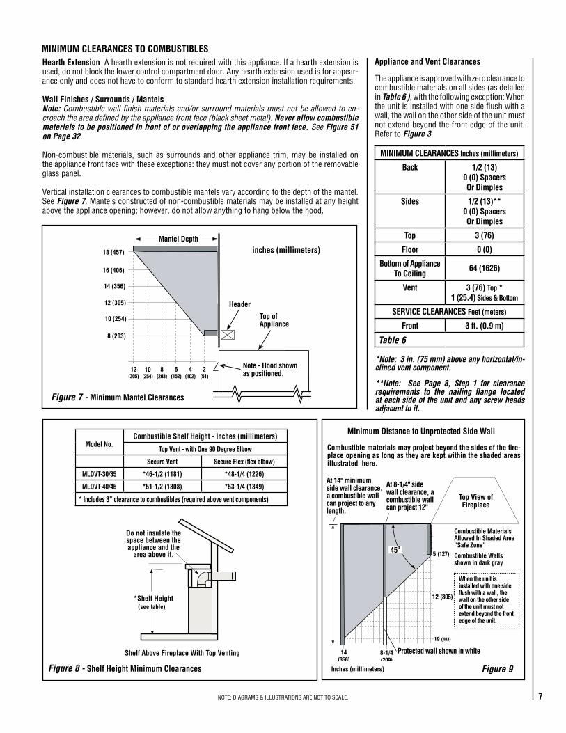
Step 2. ROUTING GAS LINE
Routea1/2"(13mm)gaslinetotheleftsideoftheappllianceasshownin Figure 11.Gaslinesmustberouted,constructedandmadeofmaterialsthatareinstrictaccordancewithlocal codesand regulations. All appliancesarefactory-equippedwithaflexiblegas lineconnector and 1/2 inch shutoff valve. (See Step 6 on Page 24 ).
Step 7.(Page25)Checkoutapplianceopera-tion.
Step 8.(Page26)Installthelogs,decorativevolcanicstoneandglowingembers.
Step 9. (Page 30) Install glass door frameassembly.
Step �0. (Page30)Adjust burner to ensureproperflameappearance.
Step ��.(Page32)Installthehoods.
Step �. FRAMING
FrametheseappliancesasillustratedinFig-ures 12 and 13 on Pages 9 and 10 (Figure 13appliestocornerframinginstallationsonly).AllframingdetailsmustallowforaminimumclearancetocombustibleframingmembersasshowninTable 6 on Page 7.
If the appliance is to be elevated above floorlevel, a solid continuous platform must beconstructed.
Headersmaybeindirectcontactwiththeappli-ancetopspacerswhentheyarebentupverticallymaintainingthe3"clearancetothefireplacetop,butmustnotbesupportedbythemornotchedtofitaroundthem.Allconstructionabovetheappliancemustbeselfsupporting. DO NOTusetheapplianceforstructuralsupport.
The fireplace should be secured to the sideframing members using the unit's nailingflanges-onetopandbottomoneachsideofthefireplacefront.SeeFigure 10. Use8dnailsortheirequivalent.
DETAILED INSTALLATION STEPS
Theapplianceisshippedwithallgascontrolsandcomponentsinstalledandpre-wired.Re-movetheshippingpad,exposingthefrontglassdoor.RemovecontrolpanelperinstructionsonPage 24. Open the two latches (locatedunder the firebox floor) securing the glassdoor.Remove thedoorby tilting it outwardat thebottomand lifting itup.Set thedoorasideprotectingitfrominadvertentdamage.See Figure 46 on Page 30.
TYPICAL INSTALLATION SEQUENCE
The typical sequence of installation follows,however,eachinstallationisuniqueresultinginvariationstothosedescribed.
SeethePagenumbersreferencesinthefollow-ingstepsfordetailedprocedures.
Step �. (Page8)Constructtheappliancefram-ing.Positiontheappliancewithintheframingandsecurewithnailingbrackets.Benduptheappropriateheaderspacingguidesforthedrywall/finishmaterialthicknesstobeused(see Figure 46).Benduptheouterpairfor1/2"materialsandtheinnerpairfor5/8" materials. Bend out the appropriatenailingflangesforthedrywall/finishmaterialtobeused.Nailingflangesareprovidedforflushframing,1/2inchand5/8inchframingdepths(see Figure 10).
Step 2. (Page8)Routegassupplylinetoap-pliancelocation.
Step 3.(Page11)Installtheventsystemandexteriortermination.
Step 4. (Page23)FieldWiring a. MillivoltAppliances– Installtheoperating
controlswitch(notfactoryprovided)andbringinelectricalservicelineforforcedaircirculatingblower(optionalequipment).
b. Electronic Appliances – Field wire andinstalloperatingcontrolswitch.
Step 5.(Page24)Installblowerkit(optionalequipment).
Step 6. (Page 24) Make connection to gassupply.
Figure 10
Note: The nailing flanges, combustible membersand screw heads located in areas directly adjacentto the nailing flanges, are EXEMPT from the �/2”clearance to combustible requirements for thefirebox outer wrapper. Combustible framing may bein direct contact with the nailing flanges and maybe located closer than �/2” from screw heads andthe firebox wrapper in areas adjacent to the nailingflanges. Frame the opening to the exact dimensionsspecified in the framing details of this manual.
Nailing Flanges AreProvided At All FourCorners At 5/8”, �/2”And Flush Settings
SideFraming
UnitNailing Flange
Left Side Front Corner of Fireplace Shown (Right Side Requirements the Same)
Unit Being Secured By Its Nailing FlangesTo The Framing

9NOTE:DIAGRAMS&ILLUSTRATIONSARENOTTOSCALE.
FIREPLACE SPECIFICATIONS
Vent Size
Co-axial DV Vent Size
4-�/2" Inner 7-�/2" Outer
Vertical Venting Through the Ceiling:Frame ceiling opening -Useaplumblinefromtheceilingabovetheappliancetolocatecenteroftheverticalrun.Cutand/orframeanopening,10-1/2"x10-1/2"(267mmx267mm)insidedimensions,aboutthiscentermark(see Figure 16).
Notes
All specifications, ratings and dimensions are subject to change without notice.
Input (BTU) - MV & Electronic
Natural & Propane Gas
Models Input Rate (BTU / HR)
MLDVT-30N �3,500
MLDVT-30P �2,500
MLDVT-35N �6,000
MLDVT-35P �5,000
MLDVT-40N 22,000
MLDVT-40P 20,000
MLDVT-45N 23,000
MLDVT-45P 22,000
Efficiencies %
Natural Gas Propane
Models AFUE P4 AFUE P4
MLDVT-30 57 55.6 58 56.�
MLDVT-35 57.5 55.6 59.0 58.�
MLDVT-40 63 58.6 62.3 59.5
MLDVT-45 63 60 64 62
Viewable Glass Size
30" Model 24-�/4" Wide 20-�/4" High
35" Model 29-�/4" Wide 20-�/4" High
40" Model 34-�/4" Wide 25-�/4" High
45" Model 39-�/4" Wide 25-�/4" High
Figure 12
Framing
A
BC
7(�78)
5-�/8�2-�/8(308)
�0-�/2(267)
VENT FRAMING -TOP VENT WITH ONE90° ELBOW
Framing should be constructedof 2x4 or larger lumber
Inches (mm)
D
(�30)
D is the required framing depth dimension when thefinish material (drywall) thickness is �/2 in. (�3mm)
A�/2
Framing Dimensions
Model No. A B C D
MLDVT-30in. 30-�/4 35-�/4 39-�/4 �6
mm 768 895 997 406
MLDVT-35in. 35-�/4 35-�/4 39-�/4 �6
mm 895 895 997 406
MLDVT-40in. 40-�/4 40-�/4 44-�/4 �6
mm �022 �022 ��24 406
MLDVT-45in. 45-�/4 40-�/4 44-�/4 �6
mm ��49 �022 ��24 406
.oNledoM E F G H J K L M
.ni
mmMLDVT-35
32-�/4
8�9
28-�/8
7�5
23-�/4
587
32
8�3
35-�/4
892
25
635
�2-�/2
3�7
33
838
.nimm
MLDVT-4037-�/4
946
33-�/8
84�
28-�/4
7�4
37
940
40-�/4
�0�9
30
762
�5
38�
38
965
.ni
mmMLDVT-30
32-�/4
8�9
28-�/8
7�5
23-�/4
587
27
686
30-�/4
768
20
508
�0
354
28
7��
.nimm
MLDVT-4537-�/4
946
33-�/8
84�
28-�/4
7�4
42
�067
45-�/4
��49
35
889
�7-�/2
445
43
�092
J
Front View
H
GF
E
M
K
L
Top View
*CONCENTRIC FLUEFLUE - 4-�/2 (��4)COMBUSTION AIR- 7-�/2 (�90)
9-�/4 (235)
�/2(�3)
�6 (406)
�-5/8 (42)
NOTE - Eyebrowhood shown.
GAS INLETKNOCKOUT
(Other Side)
Right Side View
5-7/8(�49)
NOTE - It is recommedned that the gas be studed in from the leftside only.
3 (76)
3 (76)
9-�/2(24�)
ELECTRICAL INLETKNOCKOUT - 2-3/4 X 2(70 X 5�) COVER PLATE(With KNOCKOUT -Right Side Only)
OPTIONALELECTRICAL
INLET KNOCKOUT,REQUIRING A FIELD
PROVIDEDJUNCTION BOX
(Either Side)

�0 NOTE:DIAGRAMS&ILLUSTRATIONSARENOTTOSCALE.
FIREPLACE FRAMING SPECIFICATIONS
Never use galvanized or plastic pipe. RefertoTable 7 forpropersizingofthegassup-plyline,ifblackironpipeisbeingused.Gaslinesmustberouted,constructedandmadeofmaterialsthatareinstrictaccordancewithlocalcodesandregulations.Werecommendthataqualifiedindividualsuchasaplumberorgasfitterbehiredtocorrectlysizeandroutethegassupplylinetotheappliance.Installingagassupplylinefromthefuelsupplytotheapplianceinvolvesnumerousconsiderationsofmaterials,protection,sizing,locations,controls,pressure,sediment,andmore.Certainlynooneunfamiliarandunqualifiedshouldattemptsizingorinstallinggaspiping.
Schedule 40Black Iron Pipe
Inside Diameter (Inches)
Schedule 40 PipeLength (feet)
NaturalGas
PropaneGas
0-10 1/2 3/8
10-40 1/2 1/2
40-100 1/2 1/2
100-150 3/4 1/2
150-200 3/4 1/2
Table 7
• Apipejointcompoundratedforgasshouldbeusedonthethreadedjoints.Ensure propane resistant compounds are used in propane applications. Be very careful that the pipecompounddoesnotgetinsidethepipe.
• Itisrecommendedtoinstallasedimenttrapinthesupplylineascloseaspossibletotheappliance.AppliancesusingPropaneshouldhaveasedimenttrapatthebaseofthetank.
• Checkwithlocalbuildingofficialforlocalcoderequirements(i.e.arebelowgradepenetrationsofthegaslineallowed?,etc).
IMPORTANT: If propane is used, be aware that if tank size is too small (i.e. under 100-lbs, if this is the only gas appliance in the dwelling. Ref. NPFA 58), there may be loss of pressure, resulting in insufficient fuel delivery (which can result in sooting, severe delayed ignition or other malfunctions). Any damage resulting from an improper installation, such as this, is not covered under the limited warranty.
Proper Sizing of Gas Line
Properly size and route the gas supply linefromthesupplyregulatortotheareawheretheappliance is tobe installedperrequirementsoutlinedintheNationalFuelGasCode,NFPA54-latestedition(USA)orCAN/CSA-B149.1-latestedition(Canada).
Notes:• All appliances are factory-equipped with a
flexiblegaslineconnectorand1/2inchshutoffvalve(seeFigure 37onPage 24 ).
• SeeMassachusetts RequirementsonPage 4foradditionalrequirementsforinstallationsinthestateofMassachusettsintheUSA.
• ThegassupplylineshouldNotbeconnectedtotheapplianceuntilStep 6(Page 24 ).
Figure 13 - Corner Framing with Horizontal Termination
Inches(millimeters)
C
Back wall of chase/enclosure(including any finishing materials)
D
E
A
B
7 (�78)
.oNledoM A B D E
MLDVT-40
MLDVT-35 351/4 571/2 405/8 283/4in.
895 1461 1032 730mm
401/4
10226113/16
15544311/32
11013011/16
779
in.mm
C
133/4
349
151/8384
in.mm
MLDVT-30301/4
768
533/16
13503729/32
963
2613/16
681
121/4
311
MLDVT-45in.
mm
451/4
1149661/8
1680
461/16
1170
325/8
829161/2
419

��NOTE:DIAGRAMS&ILLUSTRATIONSARENOTTOSCALE.
Installation of Vent Restrictor
A vent restrictor may be needed with thisappliance. The restrictor is installed in theappliancetopflueoutletasshowninFigure 14,eitherbeforeaddingvent,fromabove,orafterinstallationofventfrombelow,withinthefirebox.Therestrictorisselfsecuringthroughapositivefrictionfit.
Determinetheventingfortheappliance.If the vent run will include at least 8 feet of vertical rise, then install the restrictor in the appliance collar before connecting any vent (Refer to Figure 14 ).Placetherestrictorinsidetheap-plianceventcollarandpressinplace.
Note: The restrictor is included within the firebox.
Select Venting System - Horizontal or Vertical
Withtheappliancesecuredinframing,determineventroutingandidentifytheexteriortermina-tionlocation.Thefollowingsectionsdescribevertical (roof) and horizontal (exterior wall)ventapplications.Refertothesectionrelatingtoyourinstallation. A list of approved venting components is shown on Pages 32 and 33.
Step 3. INSTALL THE VENT SYSTEM
General Information
These instructions should be used as a guideline and do not supersede local codes in any way. Install vent according to local codes, these instructions, the current National Fuel Gas Code (ANSI-Z223.�) in the USA or the current standards of CAN/CSA-B�49.� in Canada.
Clearance in accordance with local installa-tion codes and the requirements of the gas supplier.
Dégagement conforme aux codes d'installation locaux et aux exigences du foumisseunde gaz.
Use only approved venting components. See Approved Vent Components on Page 2.
These fireplaces must be vented directly to the outside.
The vent system may not service multipleappliances,andmustneverbeconnectedtoaflueservingasolidfuelburningappliance.Theventpipeistestedtoberuninsideanenclosingwall(suchasachase).Thereisnorequirementforinspectionopeningsintheenclosingwallatanyofthejointsintheventpipe.
Figure 14
Vent Restrictor Installation(Top Vent)
A vent restrictor may be needed when vertical-ly terminating the vent system above the roof (when using the appliance top vent), install vent restrictor in the top vent of the fireplace outlet on all MLDVT series models. If needed,
install the restrictor orientated as shown, either from inside or outside the unit,in the
inner fireplace collar.
Appliance TopVent Outlet
Restrictor
InnerFireplaceCollar

�2 NOTE:DIAGRAMS&ILLUSTRATIONSARENOTTOSCALE.
TRAHCHTGNELNOITCESTNEVnoitceSlanimoN)sehcni(htgneL 6 2� 42 63 84 T
OTAL
QTY
noitceSteN)sehcni(htgneL 2/�-4 2/�-0� 2/�-22 2/�-43 2/�-64
tneVfothgieH snoitceStneVforebmuN
sehcni tf
441 21 1 0 0 0 3 4
051 5.21 0 1 0 0 3 4
5.451 578.21 1 1 0 0 3 5
5.061 573.31 0 2 0 0 3 5
5.271 573.41 0 0 0 5 0 5
771 57.41 1 0 0 5 0 6
381 52.51 0 1 0 5 0 6
681 5.51 0 0 0 0 4 4
5.091 578.51 1 0 0 0 4 5
5.691 573.61 0 1 0 0 4 5
5.502 521.71 0 1 1 5 0 7
702 52.71 0 0 0 6 0 6
5.112 526.71 1 0 0 6 0 7
5.712 521.81 0 1 0 6 0 7
5.922 521.91 0 0 1 6 0 7
5.232 573.91 0 0 0 0 5 5
732 57.91 1 0 0 0 5 6
5.142 521.02 0 0 0 7 0 7
642 5.02 1 0 0 7 0 8
252 12 0 1 0 7 0 8
462 22 0 0 1 7 0 8
672 32 0 0 0 8 0 8
972 52.32 0 0 0 0 6 6
5.082 573.32 1 0 0 8 0 9
5.382 526.32 1 0 0 0 6 7
5.982 521.42 0 1 0 0 6 7
5.103 521.52 0 0 1 0 6 7
5.013 578.52 0 0 0 9 0 9
513 5.62 1 0 0 9 0 01
5.523 521.72 0 0 0 0 7 7
033 5.72 1 0 0 0 7 8
633 82 0 1 0 0 7 8
543 57.82 0 0 0 01 0 01
5.943 521.92 1 0 0 01 0 11
273 13 0 0 0 0 8 8
5.673 573.13 1 0 0 0 8 9
5.973 526.13 0 0 0 11 0 11
5.814 578.43 0 0 0 0 9 9
324 52.53 1 0 0 0 9 01
564 57.83 0 0 0 0 01 01
TRAHCHTGNELNOITCESTNEVlanimoN
htgneLnoitceS)sehcni(
6 2� 42 63 84TOTAL
QTY
noitceSteN)sehcni(htgneL 2/�-4 2/�-0� 2/�-22 2/�-43 2/�-64
tneVfothgieH snoitceStneVforebmuN
sehcni tf
5.4 573.0 1 0 0 0 0 1
9 57.0 2 0 0 0 0 2
5.01 578.0 0 1 0 0 0 1
51 52.1 1 1 0 0 0 2
5.91 526.1 2 1 0 0 0 3
12 57.1 0 2 0 0 0 2
5.22 578.1 0 0 1 0 0 1
5.52 521.2 1 2 0 0 0 3
5.13 526.2 0 3 0 0 0 3
5.43 578.2 0 0 0 1 0 1
5.73 521.3 1 1 1 0 0 3
5.34 526.3 0 2 1 0 0 3
54 57.3 0 0 2 0 0 2
5.64 578.3 0 0 0 0 1 1
5.94 521.4 1 0 2 0 0 3
15 52.4 1 0 0 0 1 2
5.55 526.4 0 1 2 0 0 3
75 57.4 0 0 1 1 0 2
66 52.5 0 2 2 0 0 4
5.76 526.5 0 0 3 0 0 3
96 57.5 0 0 0 2 0 2
27 6 1 0 3 0 0 4
5.37 521.6 1 0 0 2 0 3
5.97 526.6 0 1 0 2 0 3
18 57.6 0 0 0 1 1 2
09 5.7 0 2 1 0 1 4
5.19 526.7 0 0 2 0 1 3
39 57.7 0 0 0 0 2 2
69 8 1 0 1 2 0 4
5.79 521.8 1 0 0 0 2 3
201 5.8 2 0 0 0 2 45.301 526.8 0 0 0 3 0 3
801 9 1 0 0 3 0 4
411 5.9 0 2 0 0 2 4
711 57.9 1 0 5 0 0 6
5.811 578.9 1 1 0 3 0 5
621 5.01 0 0 1 3 0 4
5.031 578.01 1 0 1 3 0 5
531 52.11 0 0 6 0 0 6
831 5.11 0 0 0 4 0 4
5.931 526.11 0 0 0 0 3 3
5.241 578.11 1 0 0 4 0 5
Note: Convert inches into metric equivalent measurement, as follows:
Millimeters (mm) = Inches x 25.4Centimeters (cm) = Inches x 2.54 Meters (M) = Inches x .0254
Table 8a
Table 8b
Figure 15
SV4.5CGV-�Termination SV4.5FA OR
SV4.5FB FlashingAND SV4.5SCSTORM COLLAR
uSV4.5VFFirestop/Spacer
SV4.5L6/�2/24/36/48Vent Sections
60’ Max(�8.3 M)
�" (25.4 mm)MinimumClearance toCombustibles
uWhen using Secure Flexuse Firestop/Spacer
SF4.5VF
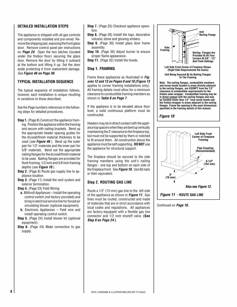
VERTICAL TERMINATION SYSTEMS (ROOF)
See Figure 15 on Page 12 and Figures 23-25 on Pages 15 and 16 andtheirassociatedVerticalVentTableswhichillustratethevariousverticalventingconfigurationsthatarepossibleforusewiththeseappliances.Secure VentpipeapplicationsareshownintheseFigures;Secure Flex pipemay alsobeused.AVerticalVentTablesummarizeseachsystem’sminimumandmaximumverticalandhorizontallengthvaluesthatcanbeusedtodesignandinstalltheventcomponentsinavarietyofapplications.
Both these vertical vent systems terminatethrough the roof. The minimum vent heightabovetheroofand/oradjacentwallsisspeci-fiedinANSIZ223.1-(latestedition)(InCanada,thecurrentCAN/CSA-B149.1installationcode)bymajorbuildingcodes.Alwaysconsultyourlocalcodesforspecificrequirements.AgeneralguidetofollowistheGasVentRule(refertoFigure 4 on Page 5).
Vertical (Straight) Installation
Determine the number of straight vent sec-tionsrequired.4-1/2"(114mm),10-1/2"(267mm), 22-1/2" (572 mm), 34-1/2" (876 mm)and 46-1/2" (1181 mm) net section lengthsareavailable(seeTables 8a and 8bandPage 32 - Vent Sections).Plantheventlengthssothatajointdoesnotoccurattheintersectionofceilingorroofjoists.RefertotheVentSectionLengthChart.
�3NOTE:DIAGRAMS&ILLUSTRATIONSARENOTTOSCALE.
C. Attach vent components to each other -Otherventsectionsmaybeaddedtothepreviouslyinstalledsectioninaccordancewiththerequire-mentsoftheverticalventFiguresandTables.Toaddanotherventcomponenttoalengthofventrun,alignthedimpledendovertheinclinedchannelendofthepreviouslyinstalledsection,adjustingtheradialalignmentuntilthefourlock-ingdimplesarealignedwiththeinletsofthefourinclinechannelsoftheprevioussection.
Pushtheventcomponentagainsttheprevioussection until it fully engages, then twist thecomponentclockwiserunningthedimplesdownandalongtheinclinechannelsuntiltheyseatattheendofthechannels.This seating position is indicated by the alignment of the arrow and dimple as shown inFigure 17.
D. Install firestop/spacer at ceiling -WhenusingSecureVent,useSV4.5VFfirestop/spaceratceilingjoists;whenusingSecureFlex,useSF4.5VFfirestop/spacer.Ifthereislivingspaceabove the ceiling level, the firestop/spacermustbe installedon thebottomsideof theceiling.Ifatticspaceisabovetheceiling,thefirestop/spacermustbeinstalledonthetopsideofthejoist.Routetheventsectionsthroughtheframedopeningandsecurethefirestop/spacerwith8dnailsorotherappropriatefastenersateachcorner.Remember to maintain �" (25 mm) clearance to combustibles, framing members, and attic or ceiling insulation when running vertical chimney sections. Attic insulation shield (H3907) may be used to obtain the required clearances indicated here. See installation accessories Pages 32 and 33. Thegapbetweentheventpipeandaverticalfirestopcanbesealedwithnon-com-bustiblecaulking.
Figure 17
Align the dimple (4 places) of the upper vent section with the opening of the locking incline channel on the lower vent section or appliance collar. Twist vent component clockwise to engage and seal until arrow and dimple align.
Dimple
Locking Incline Channel
Connected Vent Sections
Arrow
Arrow
Appliance Collar or Vent Section
Figure 16
Effective Vent Length
Model Effective Length
SV4.5L6 4-�/2"
SV4.5L�2 �0-�/2"
SV4.5L24 22-�/2"
SV4.5L36 34-�/2"
SV4.5L48 46-�/2"
Table 9
�0-�/2” Min.(267mm)
�0-�/2” Min.(267mm)
PlumbBob
RoofFraming
CeilingFraming
Vertical (Offset) Installation
Analyze the vent routing and determine thequantitiesofventsectionsandnumberofelbowsrequired.Refer toVertical Vent Figures and Tables on Pages �5 and �6toselectthetypeof vertical installation desired. Vent sectionsareavailableinnetlengthsof4-1/2"(114mm),10-1/2"(267mm),22-1/2"(572mm),34-1/2"(876mm)and46-1/2"(1181mm).RefertotheVent Section Length Charts on Page �2 foranaidinselectinglengthcombinations.Elbowsareavailablein90°and45°configurations.RefertoFigure 19 on Page �4 fortheSV4.5E45andSV4.5E90elbowdimensionalspecifications.
Where required, a telescopic vent section (SV4.5LA)maybeusedtoprovidetheinstallerwithanoptionininstallingintightandconfinedspacesorwheretheventrunmadeupoffixedlengthpiecesdevelopsajointinaundesirablelocation,orwill notbuildup to the requiredlength.TheSV4.5LATelescopicVentSectionhasaneffectivelengthoffrom1-1/2"(38mm)to7-1/2"(191mm).TheSV4.5LAisfittedwithalockinginclinedchannelend(identicaltoanormalventsectioncomponent)andaplainendwith3pilotholes.SliptheplainendoverthelockingchannelendofastandardSV4.5ventcomponenttherequireddistanceandsecurewiththreescrews.
Toattachaventcomponenttotheappliancecollar,alignthedimpledendoverthecollar,adjustingtheradialalignmentuntilthefourlockingdimplesarealignedwiththeinletofthefourinclinedchannelson thecollar(refer to Figure 17). Push theventcomponentagainstthecollaruntilitfullyengages,thentwistthecomponentclockwise,runningthedimplesdownandalongtheinclinechannelsuntiltheyseatattheendofthechan-nels.TheunitizeddesignoftheSecure Ventcomponentswillengageandsealboththeinnerandouterpipewithouttheneedforsealantorscrews.Ifdesired,a#6x1/2"screwmaybeusedatthejoint,butisnotrequiredasthepipewillsecurelylockwhentwisted.
Note: An elbow may also be attached to the appliance collar. Attach in the same manner as you would a vent section.
Maintain a minimum �" (25 mm) clearance to combustible materials for all vertical elements. Clearances for all horizontal elements are 3" (76 mm) on top, �" (25 mm) on sides and �" (25 mm) on the bottom.
A.Frame ceiling opening -Useaplumblinefromtheceilingabovetheappliancetolocatecenteroftheverticalrun.Cutand/orframeanopening,10-1/2"x10-1/2"(267mmx267mm)inside dimensions, about this center mark(Figure 16 ).
B. Attach vent components to appliance -Secure VentSV4.5directventsystemcompo-nentsareunitizedconcentricpipecomponentsfeaturingpositivetwistlockconnections(see Figure 17).
Alloftheappliancescoveredinthisdocumentarefittedwithcollarshavinglockinginclinedchannels.Thedimpledendoftheventcom-ponentsfitovertheappliancecollartocreatethepositivetwistlockconnection.
Blocking
Support Straps(Plumber's tape)
8 feet (2.4 m)Maximum
�/2 inch (�2.7 mm) minimum clearance to combustibles
Figure 18

�4 NOTE:DIAGRAMS&ILLUSTRATIONSARENOTTOSCALE.
Iftheventsystemextendsmorethan5feet(1.5m)abovetheroofflashing,stabilizersmaybenecessary.Additionalscrewsmaybeusedatsectionjointsforaddedstability.Guidewiresmaybeattachedtothejointforadditionalsup-portonmultiplejointconfigurations.
G.Continue installation of horizontal/inclined sections -Continuewiththeinstallationofthestraightventsectionsinhorizontal/inclinedrunasdescribedinStep C.Installsupportstrapsevery5ft.(1.52m)alonghorizontal/inclinedventrunsusingconventionalplumber’stape.See Page 17, Figure 26. It is very important that the horizontal/inclined run be maintained in a straight (no dips) and recommended to be in a slightly elevated plane, in a direction away from the fireplace of 1/4 " rise per foot (20 mm per meter) which is ideal,thoughriseperfootrunratiosthataresmallerareacceptableallthewaydowntoatornearlevel.Useacarpenter’sleveltomeasurefromaconstantsurfaceandadjustthesupportstrapsasnecessary.
E.Support the vertical vent run sections -Note - Proper venting support is very important. The weight of the vent must not be supported by the fireplace in any degree.
Support the vertical portion of the ventingsystemevery8feet(2.4m)abovethefireplaceventoutlet.
Onemethodofsupportisbyutilizingfieldpro-videdsupportstraps(conventionalplumber'stape).Securetheplumber'stapetotheframingmemberswithnailsorscrews. Loopthetapearoundthevent,securingtheendsofthetapetotheframing.Ifdesired,sheetmetalscrews#6x1/2"lengthmaybeusedtosecurethesupportstrapstotheventpipe.RefertoFigure 18.
F. Change vent direction to horizontal/inclined run -Attransitionfromortoahorizontal/in-clinedrun,installtheSV4.5E45andSV4.5E90elbowsinthesamemannerasthestraightventsections.Theelbowsfeatureatwistsectiontoallowthemtoberoutedaboutthecenteraxisof their initialcollarsection toalignwith therequireddirectionofthenextventrunelement.Twist elbow sections in a clockwise direction only so as to avoid the possiblity of unlocking any of the previously connected vent sections.SeeFigure 19.
J. Install the storm collar -Installthestormcollar, supplied with the flashing, over thevent/flashingjoint.SeeFigure 21. Loosenthestormcollarscrew.Slidecollardownuntil itmeetsthetopoftheflashing.Tightenthead-justingscrew.Applynon-combustiblecaulkingormasticaroundthecircumferenceofthejointtoprovideawatertightseal.
K. Install the vertical termination - ThefinalstepinvolvesinstallationoftheSV4.5CGV-1VerticalTermination.Extendtheventsectionsto theheight as shown in the "Vertical ventterminationsection" inFigure 4 onPage 5.TheSV4.5CGV-1VerticalTermination(Figure 22)canbeinstalledintheexactsamefashionasanyotherSecure Ventsection.Align thetermination over the end of the previouslyinstalledsection,adjustingtheradialalignmentuntilthefourlockingdimplesoftheterminationarealignedwiththeinletsofthefourinclinechannelsofthelastventsection.Pushtheter-minationdownuntilitfullyengages,thentwisttheterminationclockwiserunningthedimplesdownandalongtheinclinechannelsuntiltheyareseatedattheendofthechannels.
I.Install the roof flashing - Extendtheventsectionsthroughtheroofstructure.Installtheroofflashingovertheventsectionandposi-tionsuchthattheventcolumnrisesvertically(usecarpenterslevel)(Figure 21 ).Nailalongperimetertosecureflashingoradjustroofingtooverlaptheflashingedgesattopandsidesonlyandtrimwherenecessary.Sealthetopandbothsidesoftheflashingwithwaterproofcaulking.
Figure 19
7-5/8”(194 mm)4-13/16
(122 mm)
Swivel Joint(360° swivel)
SV4.5E4545° Elbow)
Swivel Joint(360° swivel)
SV4.5E9090° Elbow)
(206 mm)8-�/8"
Framing Dimensions for RoofInches (millimeters)
Pitch C D
0/�2 �0-�/2 in.(267 mm)
�0-�/2 in.(267 mm)
6/�2 �0-�/2 in.(267 mm)
�2 in.(305 mm)
�2/�2 �0-�/2 in.(267 mm)
�7 3/4 in.(45� mm)
C
D
Figure 20 - Roof Framing
VERTICAL VENT FIGURES/TABLES
Note: Secure Vent (rigid vent pipe) is shown in the Figures; Secure Flex (flexible vent pipe) may also be used.
Figure 21
Figure 22
WARNING: UNDER NO CIRCUM-STANCES, MAY SEPARATE SECTIONS OF CONCENTRIC FLEXIBLE VENT PIPE BE JOINED TOGETHER.
StormCollar
Flashing
It is important to maintain the required clear-ances to combustibles: 1" (25 mm) at all sides for all vertical runs; and 3" (76 mm) at the top, 1" (25 mm) at sides, and 1" (25 mm) at the bottom for all horizontal/inclined runs.
H.Frame roof opening -Identifylocationforventattheroof.Cutand/orframeopeningperRoofFramingChart(Figure 20 ).

�5NOTE:DIAGRAMS&ILLUSTRATIONSARENOTTOSCALE.
Notes:
• It is very important that the horizontal/inclined run be maintained in a straight (no dips) and recommended to be in a slightly elevated plane, in a direction away from the fireplace of 1/4" rise per foot (20 mm per meter) which is ideal, though rise per foot run ratios that are smaller are acceptable all the way down to at or near level.
• SV4.5VF (Secure Vent), SF4.5VF (Secure Flex) firestop/spacer must be used anytime vent pipe passes through a combustible floor or ceiling. SV4.5HF (Secure Vent), SF4.5HF (Secure Flex)firestop/spacer must be used anytime vent pipe passes through a combustible wall.
• Two 45 degree elbows may be used in place of one 90 degree elbow. The same rise to run ratios, as shown in the venting Figures for 90 elbows, must be followed if 45 degree elbows are used.
• AN ELBOW IS ACCEPTABLE AS 1 FOOT OF VERTICAL RISE EXCEPT WHERE AN ELBOW IS THE ONLY VERTICAL COMPONENT IN THE SYSTEM
(See Figure 29).
u When using Secure Flex, use Firestop / Spacer SF4.5VF
u Ceiling Firestop / Spacer (SV4.5VF)
A Vent Restrictor, as shown in Figure 14 Page 11, must be used in this application
Figure 23 - Top Vent - STRAIGHT
u Ceiling Firestop / Spacer (SV4.5VF)
vWall Firestop/Spacer (SV4.5HF)
uWhen using Secure Flex, use Firestop / Spacer SF4.5VF.
vWhen using Secure Flex, use Firestop / Spacer SF4.5HF.
H
V
V�
60 feet(�8.3 meters)
Maximum
Table A
H Maximum V Minimum
feet (meter) feet (meter)
5 (�.524) Elbow Only
5 (�.524) � (0.305)
�0 (3.048) 2 (0.6�0)
�5 (4.572) 3 (0.9�4)
20 (6.096) 4 (�.2�9)
V + V� + H = 60 feet (�8.3 m) Max.
H = 20 feet (6.096 meters) Max.
Figure 24 - Top Vent - TWO 90 DEGREE ELBOWS
Example: If 20 feet of (H) horizontal vent run is needed, then 4 feet minimum of (V) vertical vent will be required.
This table shows a 1(V) to 5(H) ratio. For every 1 foot of (V) vertical, you are allowed 5 feet of (H) horizontal run, up to a maximum horizontal run of 20 feet.
An elbow is acceptable as 1 foot of vertical rise except where an elbow is the only vertical component in the system. See Figure 29.

�6 NOTE:DIAGRAMS&ILLUSTRATIONSARENOTTOSCALE.
Maintain a minimum �" (25 mm) clearance to combustibles on the vertical sections. Clear-ances for the horizontal runs are; 3" (76 mm) on top, �" (25 mm) on sides, and �" (25 mm) at the bottom.
B.Frame exterior wall opening -Locate the center of the vent outlet onthe exterior wall according to the dimen-sions shown in Figure 12 on Page 9. Cutand/or frame an opening, 10-1/2" x 12 1/8"(267mmx308mm)insidedimensions,aboutthiscenter.
C.Frame ceiling opening -Iftheverticalrouteistopenetrateaceiling,useplumblinetolocatethecenterabovetheappliance.Cutand/orframeanopening,10-1/2"x10-1/2"(267mmx267mm)insidedimensions,aboutthiscenter(refertoFigure 16 on Page �3).
u Ceiling Firestop / Spacer (SV4.5VF) vWall Firestop/
Spacer (SV4.5HF)
uWhen using Secure Flex, use Firestop / Spacer SF4.5VFvWhen using Secure Flex, use Firestop / Spacer SF4.5HF
V
H�
H
V�
Example: If 20 feet total (H+H1) horizontal vent run is needed, then 4 feet minimum of (V) vertical vent will be required.
This table shows a 1(V) to 5(H) ratio. For every 1 foot of (V) vertical, you are allowed 5 feet of (H+H1) horizontal run up to a maximum total horizontal run of 20 feet.
An elbow is acceptable as 1 foot of vertical rise except where an elbow is the only vertical component in the system. See Figure 29.
Table B
H + H� Maximum V Minimum
feet (meter) feet (meter)
5 (�.524) Elbow Only
5 (�.524) � (0.305)
�0 (3.048) 2 (0.6�0)
�5 (4.572) 3 (0.9�4)
20 (6.096) 4 (�.2�9)
H + H� = 20 feet (6.096 m) Max.V + V� + H + H� = 60 ft. (�8.3 m) Max.
Figure 25 - Top Vent - THREE ELBOWS
VERTICAL VENT FIGURES/TABLES (CONTINUED)
HORIZONTAL (OUTSIDE WALL) TERMINATION SYSTEM
Figure 26 on Page �7, and Figures 27 to 32 on Pages �8 to 2� andtheirassociatedHorizontalVent Table illustrate the various horizontalventing configurations that are possible forusewiththeseappliances.Secure VentpipeapplicationsareshownintheseFigures;Secure Flexpipemayalsobeused.AHorizontalVentTablesummarizeseachsystem’sminimumandmaximumverticalandhorizontallengthvaluesthatcanbeusedtodesignandinstalltheventcomponentsinavarietyofapplications.
Bothofthesehorizontalventsystemsterminatethroughanoutsidewall.BuildingCodeslimitorprohibitterminatinginspecificareas.RefertoFigure 6on Page 6 forlocationguidelines.
Secure VentSV4.5directventsystemcompo-nentsareunitizedconcentricpipecomponentsfeaturingpositivetwistlockconnection,(refer to Figure 17on Page �3). All of the appli-ancescoveredinthisdocumentarefittedwithcollarshaving locking inclinedchannels.Thedimpledendoftheventcomponentsfitovertheappliancecollartocreatethepositivetwistlockconnection.
A.Plan the vent run -Analyze the vent routing and determine thetypes and quantities of sections required4-1/2"(114mm),10-1/2"(267mm),22-1/2"(572mm),34-1/2"(876mm)and46-1/2"(1181mm)netsectionlengthsareavailable.Plantheventlengthssothatajointdoesnotoccurattheintersectionofceilingorroofjoists.Makeallow-ancesforelbowsasindicatedinFigure 19.

�7NOTE:DIAGRAMS&ILLUSTRATIONSARENOTTOSCALE.
Support Brackets
BuildingSupportFraming
SV4.5E90Elbow
Ceiling
Fireplace
SV4.5L6/�2/24/36/48Vent Sections
VerticalRise
Support Bracket SpacingEvery 5 ft (�.52 m)
See Figure 15 on Page �2 or Figure 18 on Page �3 for vertical vent section support.
TYPICAL HORIZONTAL VENT INSTALLATION
u When Using Secure Flex, Use Firestop / Spacer SF4.5VF
u Firestop / SpacerSV4.5VF
Figure 26
TypicalTermination
Shown
TypicalTermination
Shown
ExteriorWall
Horizontal / Inclined Run
Pushtheventcomponentagainsttheprevioussection until it fully engages, then twist thecomponentclockwiserunningthedimplesdownandalongtheinclinechannelsuntiltheyseatattheendofthechannels.This seating position is indicated by the alignment of the arrow and dimple as shown inFigure 17 on Page �3.
F.Install firestop/spacer at ceiling - WhenusingSecureVent,useSV4.5VFfirestop/spaceratceilingjoists;whenusingSecureFlex,useSF4.5VFfirestop/spacer.
Ifthereislivingspaceabovetheceilinglevel,the firestop/spacer must be installed on thebottom side of the ceiling. If attic space isabovetheceiling,thefirestop/spacermustbeinstalledonthetopsideofthejoist.Routetheventsectionsthroughtheframedopeningandsecurethefirestop/spacerwith8dnailsorotherappropriatefastenersateachcorner.
Remember to maintain �" (25 mm) clearance to combustibles, framing members, and attic or ceiling insulation when running vertical chimney sections.
G.Support the vertical run sections - See Section E on Page �3.
H. Change vent direction -Attransitionfromortoahorizontal/inclinedrun,installtheSV4.5E45andSV4.5E90elbowsinthesamemannerasthestraightventsections.
The elbows feature a twist section to allowthemtoberoutedaboutthecenteraxisoftheirinitialcollarsectiontoalignwiththerequireddirectionofthenextventrunelement. Twist elbow sections in a clockwise direction only so as to avoid the possibility of unlocking any of the previously connected vent sections. See Figure 17 on Page �3.
I.Continue installation of horizontal/inclined sections -Continuewiththeinstallationofthestraightventsectionsinhorizontal/inclinedrunasdescribedinStep E.Installsupportstrapsevery5ft.(1.52m)alonghorizontal/inclinedventrunsusingconventionalplumber’stape.
SeeFigure 26. It is very important that the horizontal/inclined run be maintained in a straight (no dips) and recommended to be in a slightly elevated plane, in a direction away from the fireplace of 1/4" rise per foot (20 mm per meter) which is ideal,thoughriseperfootrunratiosthataresmallerareacceptableallthewaydowntoatornearlevel.
It is important to maintain the required clear-ances to combustibles: 1" (25 mm) at all sides for all vertical runs; and 3" (76 mm) at the top, 1" (25 mm) at sides, and 1" (25 mm) at the bottom for all horizontal/inclined runs.
Use a carpenters level to measure from aconstantsurfaceandadjustthesupportstrapsasnecessary.
D. Attach vent components to appliance - Toattachaventcomponenttotheappliancecollar,alignthedimpledendoverthecollar,adjustingtheradialalignmentuntilthefourlockingdimplesarealignedwiththeinletsofthefourinclinechannelsonthecollar(see Figure 17on Page �3).
Push the vent component against the collaruntilitfullyengages,thentwistthecomponentclockwise,runningthedimplesdownandalongtheinclinechannelsuntiltheyseatattheendofthechannels.
The unitized design of the Secure Ventcomponents will engage and seal both theinnerandouterpipeelementswiththesameprocedure.Sealantandsecuringscrewsarenotrequired.
Note: An elbow may also be attached to the appliance collar. Attach in the same manner as you would a vent section.
E. Attach vent components to each other -Otherventsectionsmaybeaddedtothepre-viouslyinstalledsectioninaccordancewiththerequirementsoftheventtables.Toaddanotherventcomponenttoalengthofventrun,alignthedimpledendofthecomponentovertheinclinedchannelendofthepreviouslyinstalledsection,adjustingtheradialalignmentuntilthefourlock-ingdimplesarealignedwiththeinletsofthefourinclinechannelsoftheprevioussection.

�8 NOTE:DIAGRAMS&ILLUSTRATIONSARENOTTOSCALE.
J.Assemble vent run to exterior wall -Ifnotpreviouslymeasured,locatethecenteroftheventattheexteriorwall.PrepareanopeningasdescribedinStep B.Assembletheventsystemtopointwheretheterminusofthelastsectionislocatedrelativetotheexteriorsurfacetowhichtheterminationistobeattachedasshownin Figure 28 and Table 10 on Pages �8 and �9.
Iftheterminusofthelastsectionisnotwithinthisdistance,usethetelescopic vent section SV4.5LA, as the last vent section. For wallthicknessesgreaterthanthatshowninFigure 28,refertoTable 10 on Page �9.ThisTableliststheadditionalventingcomponentsneeded(inadditiontotheterminationandadapter)foraparticularrangeofwallthicknesses.
K. Attach termination adapter - Attach theadapter(adapter-SV4.5RCH-providedwiththetermination)totheventsectionortelescopingventsection),elboworappliancecollarasshowninFigure 27 inthesamemannerasanySV4.5ventcomponent(refertoStep E).
L.Install Firestop/Spacer at exterior wall -Whenusingthetermination,installSV4.5HF(SecureVent),SF4.5HF(SecureFlex)Firestop/Spacerover theopeningat theexteriorsideoftheframing,longsideup,withthe3inchspacerclearanceatthetopasshowninFigure 27,andnailintoplace.
(TheFirestop/Spacermayalsobeinstalledovertheopeningattheinteriorsideofframing).
M. Install the Termination (SV4.5HT-2 or SV4.5HTSS)
For the last step, from outside the exteriorwall,slidethecollarsoftheterminationontotheadapter(theouterinsidetheouterandtheinner ouside the inner) until the terminationseatsagainsttheexteriorwallsurfacetowhichitwillbeattached.Orientthehousingoftheterminationwith thearrowpointedupwards.Securetheterminationtotheexteriorwall.The horizontal termination must not be recessed into the exterior wall or siding by more than the �-�/4" (32 mm)asshowninFigure 28.
Horizontal terminations have been designed to perform in a wide range of weather condi-tions. Our terminations meet or exceed industry standards.
When selecting the locations of your horizontal terminations, do not place the termina-tion where water from eaves and adjoining rooflines may create a heavy flow of cascad-ing water onto the termination cap. If the cap must be placed where the possibility of cascading water exists, it is the responsibility of the builder to direct the water away from the termination cap by using gutters or other means.
Take care to carefully follow the installation instructions for the termination, including the use of silicone caulking where required.
Figure 28
Figure 27 - INSTALLING HORIZONTAL TERMINATION
IMPORTANT: The vent termination is hot while in operation and for a period of time following the use of the fireplace. To prevent contact with hot surfaces, we recommend the use of a Termina-tion Guard. See Page 32. This can be purchased at your local dealer.
Siding
Stucco
�-�/4" Maximum Recess ofthe Square Termination intoExterior Finishing Material
Exterior Surface ofFraming
6 in. to 9-�/4 in.(�52 to 235 mm)**
Exterior Surface of SidingInterior Surface of
Finished Wall
Maximum wall thickness�0 in.(254 mm)**
SV4.5HT-2Square Termination
Shown
Maximum Extent ofVent Run SectionsRelative to ExteriorSurface of Framing
Last Vent Section. UseT e l e s c o p i c V e n tSection (SV4.5LA), IfNecessary
AdapterSV4.5RCH
SV4.5HT-2Square Termination
Shown
Venting Connection and Exterior Wall Recessingof the Horizontal Termination
*Use silicone caulking toseal the top and sides ofthe termination, up to theunderlayment, stucco, ormasonry wall surface.
**For thicknesses greater than �0”, see Table �0.
*Caulk
*Caulk
Firestop/Spacer (SV4.5HF) shownon the exterior side of the wall. It
may also be installed on theinterior side.
TypicalTermination
Shown
7"(�78)
5-�/8"(�30 mm)
�2-�/8"(308 mm)
Note: Centerline of Vent Piping isNOT the Same as the Centerline of
the Frame Opening.
6 to 48 inch Vent Section,Telescopic vent section,
Elbow or Appliance Collar
See Figure �2 on page 9for Min. Distance to Base
of Appliance.
Base of Appliance
3"(76 mm)
�"(25.4 mm)Adapter
SV4.5RCH
�0-�/2"(267 mm)

�9NOTE:DIAGRAMS&ILLUSTRATIONSARENOTTOSCALE.
See Table 10 as an aid in venting component selection for a particular range of exterior wall thicknesses.
See Table 10 as an aid in venting component selection for a particular range of exterior wall thicknesses.
H
uWallFirestop/Spacer
(SV4.5HF)
V
uWhen using Secure Flex,use Firestop/Spacer
SF4.5HF
Notes:
• Secure Vent components (rigid vent pipe and terminal) are shown in the Figures; Secure Flex components (flexible vent pipe and terminal) may also be used.
• Two 45 degree elbows may be used in place of one 90 degree elbow. The same rise to run ratios, as shown in the venting Figures for 90 elbows, must be followed if 45 degree elbows are used.
• SV4.5VF (Secure Vent), SF4.5VF (Secure Flex) firestop/spacer must be used anytime vent pipe passes through a combustible floor or ceil-ing. SV4.5HF (Secure Vent), SF4.5HF (Secure Flex) firestop/spacer must be used anytime vent pipe passes through a combustible wall.
• It is very important that the horizontal/inclined run be maintained in a straight (no dips) and recommended to be in a slightly elevated plane, in a direction away from the fireplace of 1/4" rise per foot (20 mm per meter) which is ideal, though rise per foot run ratios that are smaller are acceptable all the way down to at or near level.
• The tables show a 1(V) to 5(H) ratio up to a maximum horizontal run of 20 feet except for installations where an elbow is the only vertical vent section in the system (see Figure 29).
• AN ELBOW IS ACCEPTABLE AS 1 FOOT OF VERTICAL RISE EXCEPT WHERE AN ELBOW IS THE ONLY VERTICAL COMPONENT IN THE SYSTEM. See Figure 29.
Use Table 10 as an aid in venting component selection for a particular range of exterior wall thicknesses.
HORIZONTAL VENT FIGURES/TABLES
Figure 30 - Top Vent - ONE 90 DEGREE ELBOW - ELBOW CONNECTION NOT DIRECTLY AT APPLIANCE
Figure 29 - Top Vent -ONE 90 DEGREE ELBOW - ELBOW CONNECTION AT APPLIANCE
H
V
vWall Firestop/Spacer(SV4.5HF)
uWhen using Secure Flex,use Firestop/Spacer
SF4.5VF.
uCeilingFirestop/Spacer
(SV4.5VF)
vWhen using Secure Flex,use Firestop/Spacer
SF4.5HF.
Typical termination shown.
Typical termination shown.
Example: If 20 feet of (H) hori-zontal vent run is needed, then 4 feet minimum of (V) vertical vent will be required.
This table shows a 1(V) to 5(H) ratio. For every 1 foot of vertical, you are allowed 5 feet of (H) horizontal run up to a maximum (H) horizontal run of 20 feet.
Venting Components Required for Various Exterior Wall Thick-nesses, when using Typical Termination Kits
Vent Components Required Exterior Wall Thickness - inches (mm)
TerminationKitOnly 6to9-1/4(152to235)
TerminationKitand6In.VentSection(SV4.5L6) 10-3/4to14(273to356)
Termination Kit and 12 in.VentSection(SV4.5L12) 16-3/4to20(426to508)
Termination Kit and Tele-scopicSection(SV4.5L12) 11-3/4to20(299to508)
Table 10 Note: See Figure 28 showing wall thickness range when using SV4.5HT-2 termination kit.
Table C
H Maximum V Minimum
feet (meter) feet (meter)
3 (0.9�4) Elbow Only (30/35/40 Models)
2.5 (0.762) Elbow Only (45 Model)
Table D
H Maximum V Minimum
feet (meter) feet (meter)
5 (�.524) � (0.305)
�0 (3.048) 2 (0.6�0)
�5 (4.572) 3 (0.9�4)
20 (6.096) 4 (�.2�9)
V + H = 60 feet (�8.3 m) Max.H = 20 ft. (6.096 m) Max.
WARNING: UNDER NO CIRCUMSTANCES, MAY SEPA-RATE SECTIONS OF CONCENTRIC FLEXIBLE VENT PIPE BE JOINED TOGETHER.

20 NOTE:DIAGRAMS&ILLUSTRATIONSARENOTTOSCALE.
V
H
H�
vWall Firestop/Spacer(SV4.5HF)
vWall Firestop/Spacer(SV4.5HF)
vWhen using Secure Flex,use Firestop/Spacer
SF4.5HF. uCeilingFirestop/Spacer
(SV4.5VF)
uNote - When usingSecure FlexTM, use
Firestop/Spacer SF4.5VF.
Table E
H + H� Maximum V Minimum
feet (meter) feet (meter)
3 (0.9�4) Elbow Only
5 (�.524) � (0.305)
�0 (3.048) 2 (0.6�0)
�5 (4.572) 3 (0.9�4)
20 (6.096) 4 (�.2�9)
V + H + H� = 60 feet (�8.3 m) Max.H + H� = 20 ft. (6.096 m) Max.
Figure 31 - Top Vent - TWO 90 DEGREE ELBOWS
See Table 10 on Page 19 as an aid in venting component selection for a particular range of exterior wall thicknesses.
HORIZONTAL VENT FIGURES / TABLES (CONTINUED)
Example: If 20 feet of (H + H1) horizontal vent run is needed, then 4 feet minimum of (V) vertical vent will be required.
This table shows a 1(V) to 5(H) ratio. For every 1 foot of (V) vertical, you are allowed 5 feet of (H+ H1) horizontal run, up to a maximum horizontal run of 20 feet.
An elbow is acceptable as 1 foot of vertical rise except where an elbow is the only vertical component in the system. See Figure 29.
Typical termination shown.

2�NOTE:DIAGRAMS&ILLUSTRATIONSARENOTTOSCALE.
Example: If 20 feet total (H+H1) horizontal vent run is needed, then 4 feet minimum of (V) vertical vent will be required.
This table shows a 1(V) to 5(H) ratio. For every 1 foot of (V) vertical, you are allowed 5 feet of (H+ H1) horizontal run, up to a maximum horizontal run of 20 feet.
An elbow is acceptable as 1 foot of vertical rise except where an elbow is the only vertical component in the system. See Figure 29.
V
H
H�
V�
vWall Firestop/Spacer(SV4.5HF)
uCeilingFirestop/Spacer
(SV4.5VF)
uWhen using Secure Flex,use Firestop/Spacer
SF4.5VF.vWhen using Secure
Flex, use Firestop/SpacerSF4.5HF.
vWall Firestop/Spacer(SV4.5HF)
See Table 10 on Page 19 as an aid in venting component selection for a particular range of exterior wall thick-nesses.
Figure 32 - Top Vent - THREE 90 DEGREE ELBOWS
HORIZONTAL VENT FIGURES / TABLES (CONTINUED)
Table F
H + H� Maximum V Minimum
feet (meter) feet (meter)
5 (�.524) Elbow Only
5 (�.524) � (0.305)
�0 (3.048) 2 (0.6�0)
�5 (4.572) 3 (0.9�4)
20 (6.096) 4 (�.2�9)
H + H� = 20 feet (6.096 m) Max.V + V�+ H + H� = 60 ft. (�8.3 m) Max.
Typical termination shown.
22 NOTE:DIAGRAMS&ILLUSTRATIONSARENOTTOSCALE.
D. Install Firestop / Spacers at ceilings and walls - WhenSecureFlexpenetratesawallorceiling,afirestop/spacerisrequired:usetheSF4.5VFfirestop/spacerforceilingsandtheSF4.5HFfirestop/spacerforwalls.SeetheappropriatesectionsandFiguresshownthroughoutthevent-ingsectionfortheirinstallationrequirements.
APPLY ONLY MIL-PAC BLACK HIGH TEMPERATURE SEALANT (Cat. No. �0K8�) to the outside surface of both collars of the adapter (be especially careful to fill the grooves of the outer collar to be covered by the flexible pipe) and slide flexible pipe over inner and outer adapter collars.
� 3/4 inch (44 mm) Flexible Pipe and Adapter Outer Collar Overlap
Adapter (SV4.5RF)
Attach Adapter to Appliance Collar, or Secure Vent Sections
Flex Vent
Gear Clamps
Securing Screw - 3 Places, �20° apart (equally spaced) Just Below Gear Clamp
� 3/4 in. (44 mm) Flexible Pipe and Adapter Inner Collar Overlap
Securing Screw - 3 Places Equidistant (equally spaced) Just Below Gear Clamp)
VERTICAL OR HORIZONTAL VENTING USING SECURE FLEX KITS AND COMPONENTS
Secure Flex venting kits and componentsmay be used in any venting application inplaceofrigidSecure Vent(SV4.5)directventcomponents.Allrestrictions,clearancesandallowancesthatpertaintotherigidpipingapplytotheflexibleventing.Secure Flex kits may not be modified; also, under no circumstances may separate sections of flex pipe be joined together.
Using adapter (SV4.5RF), Secure Flex kitsmaybeaddedtotheendofaventrunmadeupofrigidSecure Vent(SV4.5)ventsectionsprovidedthatdoingsodoesnotviolateanyoftheventinglength,height,routing,horizontalto vertical ratio requirements or clearanceconsiderationsdetailedinthismanual.
Secure Flex kits come with an adapter thatcan be fitted to the inclined channel end ofthelastSecure Vent(SV4.5)ventsectioninarigidsystemintheexactsamefashionasanyotherSecure Vent section.Alignthedimpledendoftheadapteroverthepreviouslyinstalledsectionorappliancecollar,adjustingtheradialalignmentuntilthefourlockingdimplesoftheadapterarealignedwiththeinletsofthefourinclinechannelsofthelastventsectionorcollar.Pushontheadapteruntilitfullyengages,thentwisttheadapterclockwiserunningthedimplesdownandalongtheinclinechannelsuntiltheyseatattheendofthechannels.
Attach the flexible vent to the adapter as fol-lows (see also Figure 33):A. Install the Inner Flex Pipe - �.Installthesmallgearclamplooselyaround
theinnerflexibleventpipe,pushitbackoutoftheway.
2.ApplyabeadofMill-Pac Black (700° F) high temperature sealant - Catalog No. �0K8�to the inner adapter collar, approximately1/2inchfromtheend.
3.Pullandextendtheinnerflexibleventpipe.4.Slidetheinnerflexpipeovertheadaptercol-
lar.Ensuretheflexibleventpipecompletelyengagestheadaptercollartoadistanceof13/4inchesfromtheend,andthatitisfreefromdamageortears.
5.Slide thegear clampdownand tighten itfullytosecuretheflexibleventtotheadapterinnercollarapproximately3/4inchfromtheendoftheflex.
6. Install three screws �20 degrees apartthroughtheflexibleventpipeandintotheadaptercollarjustbelowthegearclamptoprovideadditionalsecuritytotheconnec-tion.
B. Install the Outer Flex Pipe - �.Installthelargegearclamplooselyaround
theouterflexibleventpipe,pushitbackoutoftheway.
2.ApplyabeadofMill-Pac Black (700° F) high temperature sealant - Catalog No. �0K8�)totheouteradaptercollar;tothegroovesofthecollarwhichextendapproximately1inchfromtheendandtotheflatsurface,approximately1-3/8inchesfromtheend.
3.Pullandextendouterflexibleventpipe.4.Slidetheouterflexpipeovertheadaptercol-
lar.Ensuretheflexibleventpipecompletelyengagestheadaptercollartoadistanceof1-3/8inchesfromtheend,andthatitisfreefromdamageortears.
5.Slide thegear clampdownand tighten itfullytosecuretheflexibleventtotheadapteroutercollarapproximately3/4inchfromtheendoftheflex.
6.Install three screws �20 degrees apartthroughtheflexibleventpipeandintotheadaptercollarjustbelowthegearclamptoprovideadditionalsecuritytotheconnec-tion.
C. Route Flex Vent -Ensurethattheflexventisproperlyroutedtoprovidetherequiredclearance.Do not allowtheflexibleventtobendinaradiustighterthan5"(127mm).RefertoFigure 34.Spaceouttheinternalflexventspacersevenly-approximatelyevery6inches-andavoidkinkingofinnerpipe.Supporthorizontalsectionsofflexwithmetalstrapsat2foot(0.61m)intervals.
E. Attach Flex Vent to Termination -Secure Flex components can be purchasedseparatelyandattachedtobulklengthsofSe-cure Flexflexibletubingcuttosizeatthejobsite.SecuretheflexibleventtotheSecure Flexterminationsinthesamemanner(see Figure 33) asitwasattachedtotheadapter.
Note: Secure Flex vent must be attached to Se-cure Flex terminations only. DO NOT substitute Secure Vent terminations or the Secure Vent adapter for Secure Flex components. The col-lars of Secure Flex terminations and adapters have a different diameter than that used with the Secure Vent pipe. Additionally, Secure Flex components have an extended length center tube for use in attaching the flexible vent.
Figure 33
Flexible Vent Section
5” (�27 mm)Radius
MinimumFigure 34
Note: Outer Pipe Is Pulled Away To Show The Detail of The Inner Pipe

23NOTE:DIAGRAMS&ILLUSTRATIONSARENOTTOSCALE.
Step 4. FIELD WIRING
CAUTION: Label all wires prior to disconnec-tion when servicing controls. Wiring errors can cause improper and dangerous operation.
ATTENTION: Au moment de l'entretien des commandes, étiquetez tous les fils avant de les débrancher. Des erreurs de cáblage peu-vent entraîner un fonctionnement inadéquat et dangereux.
Verify proper operation after servicing.
S'assurer que l'appareil fonctionne adé-quatement une fois l'entretien terminé.
RefertoSectionAformillivoltappliancesandSection B for electronic appliances. The gasvalveissetinplaceandpre-wiredatthefactoryonbothmodels.
A. Millivolt Wiring (See Figure 35 ) –
�. Appliance-mountedON/OFFburnercontrolswitch(rockerswitch)isfactoryinstalledbe-hindthebottompanel.Optionalwall-mountedswitch,thermostat,oronoftheoptionalremotecontrolkitsmayalsobeused.
2. If wall-mounted ON/OFF control switchthermostatisselected,mountitinaconvenientlocationonawallnearthefireplace.
3.Wirethecontrolswitchwithinthemillivoltcontrolcircuitusingthe15feetof2conductorwiresuppliedwiththeunit.
Note: The supplied 15 feet of 2 conductor wire has one end of each conductor connected to the gas valve circuit and the other end of each conductor placed loose inside the bottom compartment.
4.Ifanoptionalcontrolswitchisinstalled,turntheappliance-mountedON/OFFburnercontrolswitchtotheOFFposition.
CAUTION: Do Not connect the optional wall switch to a �20V power supply.
B. Electronic Wiring (See Figure 36 ) –
Note: The electronic appliance must be con-nected to the main power supply.
�. Route a 3-wire 120Vac 60Hz 1ph powersupplytotheappliancejunctionbox.
2.Removetheelectricalinletcoverplatefromthe side of the unit by removing the plate'ssecuringscrews.See Figure 12 on Page 9.
3.Removethecoverplate'sknockoutandthenfeedthepowersupplywirethroughtheknockoutopeningandintotheunitjunctionbox.
4.Connecttheblackpowersupplywiretothelower outlet's redpigtail lead and thewhitepowersupplywiretothecommon terminaloftheoutletasshowninFigure 36.
5. Connect the ground supply wire to the pigtail lead attached to outlet's green ground screw.
6.Appliance-mountedON/OFFburnercontrolswitch (rocker Switch) is factory installedbehindthebottompanel.
Optional wall-mounted switch, thermostat,oronoftheoptionalremotecontrolkitsmayalsobeused.TheappliancemountedON/OFFswitchneedstoberelocatedontotheoptionalstyleviewdoor,ifused.
Note: Remote receiver should be located in the wall, or if installed in the control compartment, pulled all the way forward and completely to the left or right against the corner posts. The door must be removed first to place the receiver in the lower control compartment.
7.Ifwall-mountedON/OFFcontrolorther-mostatistobeused,mountitinaconvenientlocationonawallnearthefireplace.
8.Ifanoptionalcontrolistobeused,wireitinthelowvoltagecircuitasshowninFigure 36.
JUNCTION BOX
WGRBK
�20 VAC
BK R
TRANSFORMER 3V
INTERMITTENT ELECTRONIC WIRING DIAGRAM
BROWN
BROWN
BLACK
BATTERY BACK-UP
BLACK (SENSOR)
BLACK (IGNITER)
SPARK TO PILOT IGNITER
IGNITER MODULE3V
RED
BK W GR
OPTIONAL BLOWERSWITCH
FAN(OPTIONAL)
PILOT
INOU
T
VENT
LO HI
THTPTH
TP
IN
ORANGE (THTP)
BLACK (TP)
GREEN (TH)
TO WALLSWITCH ORTHERMOSTAT
TP-TH
TP
TH
APPLIANCE- MOUNTEDON/OFF SWITCH(OPTIONAL)
BK/W(�)BK/W(�)
WALL-MOUNTED ON/OFF SWITCH (OPTIONAL)THERMOSTAT (OPTIONAL)
JUNCTION BOX
BLAC
K
W
GR �20
VAC
WALL MOUNTED CONFIGURATION FOR FAN SWITCH (OPTIONAL)
BK
R
WIRING DIAGRAM MILLIVOLT GAS VALVES
THERMOPILE
GAS VALVE
FAN(OPTIONAL)
Figure 35 Figure 36

24 NOTE:DIAGRAMS&ILLUSTRATIONSARENOTTOSCALE.
Gas Flex LineGas Shut-OffValve Valve Piezo Spring Door
LatchLower ControlCompartment
Figure 38
Step 5. WIRING - OPTIONAL FORCED AIR BLOWER KIT
Blower Access
Bloweraccessisthroughthefireboxbottom.Removethesubfloor,removetheburnerandremovetenscrewssecuringtheGTAassemblytothefirebox.
Anelectricaloutletboxisprovidedfortheinstal-lationoftheFBK-�00 and FBK-200forcedairblowerkit.Electricalpowermustbeprovidedtothisboxtooperatetheseblowers.
IMPORTANT: Ground supply lead must be connected to the wire attached to the green ground screw located on the outlet box. See Figure 36. Failure to do so will result in a potential safety hazard. The appliance must be electrically grounded in accordance with local codes or, in the absence of local codes, the National Electrical Code, ANSI/NFPA 70-(latest edition). (In Canada, the current CSA C22-� Canadian Electrical Code.)
Installtheblowerkitaccordingtotheinstallationinstructionsprovidedwiththekit.Repositionand reinstall the GTA assembly, burner andsubfloor.
Step 6. CONNECTING GAS LINE
All codes require a shut-off valve mountedin the supply line. The orientation of theshut-offvalveshouldfacethefront. Figure 37 illustratesthemethodforconnectingthegassupply.
The flex-line method is acceptable in theU.S., however, Canadian requirements varydependingonlocality.Installationmustbeincompliancewithlocalcodes.Theseappliancesareequippedwithagasflexlineforuseincon-nectingtheunittothegasline.
Thegasflexlinecanonlybeusedwherelocalcodespermit.SeeFigure 37 forflexlinede-scription.Theflexlineisratedforbothnaturalandpropanegas.
Figure 37 - GAS CONNECTION
Amanualshutoffvalveisalsoprovidedwiththeflexline.Thegascontrolvalveislocatedinthelowercontrolcompartment.
Accessthevalvecompartmentbyremovingthelowercontrolcompartmentpanel(see Figure 38 )byliftingandpullingthepanelforward.Thepanel ismountedonsupportingtabsattheextremerightandlefthandsides.Engagethetabsintothereliefsinthepanel.
Themillivoltandelectroniccontrolvalvehasa3/8"(10mm)NPTthreadinletport.
Secure all joints tightly using appropriate tools and sealing compounds (ensure propane resistant compounds are used in propane ap-plications). It is recommended to seal around the gas line to prevent cold air leakage.
Gaslineconnectionmaybeperformedlargelyoutsideoftheconfinesofthecontrolcompart-mentandwithouthavingtoenterthefireboxbehindtheglass.Proceedasfollows:
Acquiretheshut-offvalveandgaslexlineandpulltheassemblyforwardoutofthecompart-ment.Separatetheshut-offvalvefromthegasflexline.Determinethelengthofpipeneededtoroutethegaslinefromthelastfitting(showninFigure 11onpage 8)toapointwithinthecontrolcompartmentthatwillallowtheshut-offvalvetobeeasilyattachedbyhandtothegasflexline.
Usingpipe-dressingmaterialsappropriateforthegastype,securelyaffixtheshut-offvalvetothisdeterminedpipelengthataconvenientlocationoutsideoftheappliancelowercontrolcompartment.
�/2" x 3/8" FlareShut-Off Valve
3/8" Flex Tubing
3/8" NPT x 3/8Flare Fitting
GasValve
Flex Line Connector
Last Length Of GasPiping Attached ToShut-Off ValveBefore ConnectedTo The End Of GasLine Run (Step 6)
Note: The supplied 15 feet of 2 conductor wire has one end of each conductor connected to the gas valve circuit and the other end of each conductor placed loose inside the bottom compartment.
9.Iftheoptionalunitmounted(FRS)controlswitchisinstalled,turntheappliance-mountedON/OFF burner control switch to the OFFposition.
�0. Afterthewiringiscomplete,replacethecoverplate.
Note: No batteries to be installed in the battery holder until a power outage, or if the appli-ance is to be operated solely with two (2) "D" batteries.

25NOTE:DIAGRAMS&ILLUSTRATIONSARENOTTOSCALE.
RefertoFigure 39andinsertthelastlengthofgaspipewithitsattachedshut-offvalveintothelowercontrolcompartment,andpassitthroughthegaslineaccessholeontheleftsideoftheapplianceouterwrapper. Usingappropriatematerialsforthegastype,threadthelastlengthofpipeintotheendofthegasventrunandtighteninplaceusingapipewrenchexternal totheappliancebetweentheapplianceouterwrapperandtheframing.
Important: Turn the last piece of gas pipe in the last fitting until the shut-off valve is posi-tioned in a way that allows the shut-off valve handle to be accessed in the lower control compartment, easily operated throughout its full range of motion.
Bringtheflexlinetotheshutoffvalvebyhandandaligntheflarefittings.Tightenthefittingsbyhand,andthenusewrenchtotightencom-pletely,1/4turnatatime.
Test All Connections For Gas Leaks (Factory And Field)
Turnongassupplyandtestforgasleaks,us-ingagasleaktestsolution(alsoreferredtoasbubbleleaksolution).
Note: Using a soapy water solution (50%dishsoap,50%water)isaneffectiveleaktestsolutionbutitisnotrecommended,becausethesoapresiduethatisleftonthepipes/fittingscanresultincorrosionovertime.Never use an open flame to check for leaks.
A. Light the appliance (refer to the lightinginstructionslabelinthecontrolcompartmentorintheCareandOperationInstructions).
Figure 41
MILLIVOLT
Thermocouple
Hood Igniter Rod
3/8" Min(9 mm)
Thermopile
PilotNozzels
B.Brushalljointsandconnectionswiththegasleaktestsolutiontocheckforleaks.Ifbubblesareformed,orgasodorisdetected,turnthegascontrolknobtothe“OFF”position.Eithertightenorrefastentheleakingconnectionandretestasdescribedabove.
C. Whenthegaslinesaretestedandleakfree,besuretorinseofftheleaktestingsolution.
D.Observetheindividualtonguesofflameontheburner.Makesureallportsareopenandproducingflameevenlyacross theburner. Ifany ports are blocked, or partially blocked,cleanouttheports.
Step 7. CHECKING APPLIANCE OPERATION
With gas line installed run initial systemcheckoutbeforeclosingupthefrontoftheunit.Followthepilotlightinginstructionsprovidedin theCare andOperation Instructions. Forpiezoigniterlocationsee Figure 38 on page 24 (millivoltappliancesonly).
Note: Lighting Instructions are also found on the literature tag tied to the gas piping next to the gas valve. To access the tag, open the lower control compartment door (Figure 38 on page 24 ) by pulling the panel forward.
Whenfirstlightingtheappliance,itwilltakeafewminutesforthelinetopurgeitselfofair.Oncepurgingiscomplete,thepilotandburnerwilllightandoperateasindicatedintheinstruc-tionmanual.
Subsequent lightingof theappliancewillnotrequiresuchpurging.Inspectthepilotflame(re-movelogs,ifnecessary,handlingcarefully).
Millivolt Appliance Checkout
The pilot flame should be steady, not liftingorfloating.Flameshouldbeblueincolorwithtracesoforangeattheouteredge.
The top 3/8" (10 mm) at the pilot generator(thermopile)andthetop1/8"min(tip)ofthequickdropoutthermocoupleshouldbeengulfedinthepilotflame.
Electronic Appliance Checkout
Tolighttheburner,turn‘ON’theunitmountedOn/Offswitchortheoptionalremotewallswitch.Ensure the igniter lights the pilot. The pilotflameshouldengulf theflamerodasshowninFigure 41.
Figure 40
ELECTRONIC
PilotHood
Sensor
Igniter
Length Of Pipe With Attached Shut-Off Valve
Figure 39
Theflameshouldproject1"(25mm)beyondthehoodatallthreeports(Figure 40). Replacelogsifremovedforpilotinspection.
Tolighttheburner;turn“ON”theremotewallswitchandrotate thegasvalvecontrolknobcounterclockwisetothe“ON”position(“ON”willbeatthetopsideofthevalve).

26 NOTE:DIAGRAMS&ILLUSTRATIONSARENOTTOSCALE.
REFERENCEFirebox Accessories / Parts
Cat. No. Model No. Description
88L53 FGE Bag of Glowing Embers(� oz. rockwool)
80L42 FDVS Bag of Decorative Volcanic Stone
Glowing Embers
Bag of Glowing Embers (rockwool)
Separate into Quarter Size (separate) Pieces
Step 8. INSTALL VOLCANIC STONE, GLOWING EMBERS AND LOGS
NOTE: Turn off all electricity to the appliance before you install volcanic stone, embers and logs.
�. Remove the front glass enclosure panel (see Removing Glass Enclosure Panels onPage 30).
2. Remove log set box from firebox. Next,remove embers and volcanic stone fromcontrolcompartment.Handle logs carefully to prevent breakage.
3. Install decorative volcanic stone -Sprinklethe decorative volcanic stone in apleasingpattern(seeFigure 42).Thevolcanicstoneshouldbeplaceddirectlyontopofthefireboxbottom, along the slope and to the back attherightand leftsidesof theburner. Posi-tion any ceramic fiber liners before placingthestone.Logscanbepositionedafterthevolcanicstone.
Figure 43
WARNING: The size and position of the log set was engineered to give the appliance a safe, reliable and attractive flame pattern. Any attempt to use a different log set in the fireplace will void the war-ranty and will result in incomplete combustion, sooting, and poor flame quality.
WARNING: This appliance is not designed to burn wood. Any attempt to do so could cause irrep-arable damage to appliance and prove hazardous to your safety.
WARNING: If logs are not installed according to the log installation instructions, flame impingement and improper combustion could occur and result in soot and/or excessive production of carbon monoxide (CO), a colorless, odor-less, toxic gas.
WARNING: DO NOT attempt to install the logs until the appliance installation has been completed, the gas line connected and tested for leaks and the initial burner operation has been checked out.
Volcanic Stone
4.Placement of Glowing Embers - SeparatetheEmbers(rockwool)intopiecesaboutthesizeofaquarter(seeFigure 43).Keepthepiecesfluffedup,notmatted.Dis-tribute these pieces over the surface of theburner,asshowninFigures 44 and 45.Donotusemorethanisnecessary.Ensure that the main burner slots remain uncovered by the ember material.Positiontheembersonthesmallholesoftheemberbedarea.
Note:This appliance is provided with enough Glowing Embers for several applications, do not use all that is in a new bag at one time. For best glowing effect, replace the ember material annually.
5. Placement of Logs - Alllogsthathavelocatingnotchesorslotstohelpensurethattheyareproperlypositioned.All top logs that rest on lower logs, do soover notches, indents or nubs. Proper logplacementiscriticaltopreventsooting.Logsshouldbeplacedinthegapsbetweentheflamepeaksandshouldbepositionedsotheydonotimpingetheflames.
MLDVT-30 & MLDVT-35 - Install the five logs as Follows:
CarefullypositiontheceramicfiberlogsovertheburnerasshowninFigure 44.Logsshouldbeplacedintheordershownandperthefol-lowinginstructions.
�. Placetherearlog(1)asshown.Positionitontheleftrearlogbracket.2. Placetheleftfrontlog(2)asshown.Posi-tionitagainsttheleftfrontofthelograck.3. Placetherightfrontlog(3)asshown.Posi-tionitagainsttherightfrontofthelograck.4. Placetheleftcrosslog(4)asshown.Posi-tionitovertherearlog(1),withthefrontofthelogrestingonthelograck.5. Place the right cross log (5) as shown.Positionitovertherightlog(3),andresttherearofthelogovertherightrearbracket.
MLDVT-40 & MLDVT-45 - Install the five logs as Follows:
CarefullypositiontheceramicfiberlogsovertheburnerasshowninFigure 45.Logsshouldbeplacedintheordershownandperthefol-lowinginstructions.
�. Placetherearlog(1)asshown.Positionitontheleftrearlogbracket.2. Placetheleftfrontlog(2)asshown.Posi-tionitagainsttheleftfrontofthelograck.3. Placetherightfrontlog(3)asshown.Posi-tionitagainsttherightfrontofthelograck.
Figure 42Place Volcanaic Stone As Shown
4. Placetheleftcrosslog(4)asshown.Posi-tionitovertherearlog(1),withthefrontofthelogrestingoverlog(2).5. Place the right cross log (5) as shown.Positionitovertherightlog(3),andresttherearofthelogovertherightrearbracket.

27NOTE:DIAGRAMS&ILLUSTRATIONSARENOTTOSCALE.
MLDVT-30 & MLDVT-35 LOG PLACEMENT (model-35 shown, model-30 similar)
Figure 44Step 2
Step 3
Step 4
Step �
Log Number Description
1 RearLog 2 LeftFrontLog 3 RightFrontLog 4 LeftCrossLog 5 RightCrossLog
Catalog Number for the entire log set: MLDVT-30: H7839MLDVT-35: H7666
WARNING: Logs get very hot and will remain hot up to one hour after gas supply is turned off. Handle only when logs are cool.
Left Rear Log Bracket Right Rear Log Bracket
Rockwool(Do Not Place Rockwool Over Burner Slots)
Log RackVolcanic Stone
4 5
32
�
2
3
�
Position on the left rear log bracket
Right Rear Log Bracket
Position against the left side of the log rack
Position against the right side of the log rack
4
5
Position over rear log (�) and against log rack
Position on the right rear log bracket

28 NOTE:DIAGRAMS&ILLUSTRATIONSARENOTTOSCALE.
MLDVT-40 & MLDVT-45 LOG PLACEMENT (model-40 shown, model-45 similar)
Step 2
Step 3Step �
Step 4Figure 45
WARNING: Logs get very hot and will remain hot up to one hour after gas supply is turned off. Handle only when logs are cool.
4 5
32
�
3
5
Rockwool(Do Not Place Rockwool Over Burner Slots)
Log RackVolcanic Stone
Right Rear Log Bracket�Position on the left rear log bracket 4
2 3
Position the left front log (2) and the right front log (3) against the log rack.
32
Log Number Description
1 RearLog 2 LeftFrontLog 3 RightFrontLog 4 LeftCrossLog 5 RightCrossLog
Rest over log (�) and log (2) with the front resting on the log rack.
Position on the right rear log bracket and over log (3)
Catalog Number for the entire log set: MLDVT-40: H7667MLDVT-45: H7840

29
NOTES:

30 NOTE:DIAGRAMS&ILLUSTRATIONSARENOTTOSCALE.
Step 9. INSTALLING THE GLASS DOOR
Air Shutter Adjustment Guidelines:
Amount of Primary Air
Flame Color
Air Shutter Adjustment
If air shutter is closed too far
Flame will be orange
Air shutter gap should be increased
If air shutter is open too far
Flame will be blue
Air shutter gap should be decreased
Air Shutter Adjustment Guidelines
• Ifthereissmokeorsootpresent,firstcheckthe logsetpositioning to ensure that theflamesarenotimpingingonanyofthelogs.Ifthelogsetisproperlypositionedandasooting condition still exists, then the airshutteropeningshouldbeincreased.
• Themoreoffsetsintheventsystem,thelargertheairshutteropeningwillneedtobe.
• Anapplianceoperatedwiththeairshutteropenedtoofar,mayhaveflamesthatappearblueandtransparent.Theseweak,blueandtransparentflamesaretermedanemic.
• Propanemodelsmayexhibitflameswhichcandleorappearstringy.Ifthisispresentandpersists,adjusttheairshuttertoamoreclosedposition,thenoperatetheapplianceforafewmoreminutestoensurethattheflame normalizes and the flames do notappearsooty.
Thefollowingchart isprovidedtoaidyouinachieving the correct air shutter adjustmentforyourinstallation.
Figure 46 - INSTALLING THE GLASS DOOR
ControlCompartmentPanel
Hood
GlassDoor
HeaderSpacingTopStandoffs
FlushNailingFlange
�/2”NailingFlange
5/8”NailingFlange
Glass DoorSpring LatchRemoving Glass Enclosure Panels
(see Figure 46 )
�.Toaccesstheglassdoorsecuringlatches,firstopenthelowercontrolcompartmentdoor(Figure 46 )byliftingandpullingthebottompanelforward.
Step �0. BURNER ADJUSTMENTS
Flame Appearance and sootingProperflameappearance isaflamewhich isblueatthebaseandbecomesyellowish-orangeinthebodyoftheflame.
2.Pullthelatchesforwardanddowntoreleasethemfromthedoorchannel.
3.Pullthebottomofthedooroutafewinchesandgraspitontherightandleft.Gentlylifttorelease the door from its channel above thedoor.Pullthedoorforward.
4.Retrievetheglassdoor.Visuallyinspectthegasketon thebacksideof the frame.Gasketsurface must be clean, free of irregularitiesandseatedfirmly.
5. Position the door in front of the fireboxopeningwiththebottomofthedoorheldawayfromthefireplace(Figure 46 ).Hookthetopflangeof thedoor frameover the topof thefireboxframe.
6. Let the bottom of the door frame swinggentlyintowardsthefireplaceensuringthatthegasketseatsevenlyasthedoorframedrawsshut.Fastenthetwolatcheslocatedunderneaththefireboxfloortothedoor'svee-flange.Closeboththelatchessecurely.
7.Installthehood.Notethelocationofthethree clips inside the top air channel abovethedoor.Theclipsareequallyspacedonthetopsurfaceoftheairchannelopening.Useascrewdrivertoopentheclipsslightlyifneeded.Engagethebackedgeoftheeyebrowintotheclipstosecure.
WARNING: Do not operate appli-ance with the glass front removed, cracked or broken. Replacement of the glass should be done by a licensed or qualified service technician.
AVERTISSEMENT: Ne pas utiliser l'appareil si le panneau frontal en verre n'est pas en place, est craqué ou brisé. Confiez le remplace-ment du panneau à un technicien agréé.
Whentheapplianceisfirstlit,theentireflamemaybeblueandwillgraduallyturnyellowish-orangeduringthefirst15minutesofoperation.Ifafterashortperiodtheflamestaysloweredblue,oriftheflameisorangewithevidenceofsooting(blacktip),theairshutteropeningmayneedtobeadjusted.
If the air shutter openings closed too far,sooting may develop. Sooting is indicatedbyblackpuffsdevelopingat the tipsofverylongorangeflames.Sootingresultsinblackdepositsformingonthelogs,applianceinsidesurfacesandonexteriorsurfacesadjacenttotheventtermination.
Sootingiscausedbyincompletecombustionintheflamesandlackofcombustionairenteringtheairshutteropening.Toachieveawarmyel-lowish-orangeflamewithanorangebodythatdoes not soot, the shutter opening must beadjustedbetweenthesetwoextremes.
WARNING: Do not attempt to substitute the materials used on this door, or replace cracked or broken glass with any materials other than those provided by the appliance manufacturer.
WARNING: Handle this glass with extreme care! Tempered glass is susceptible to damage – do not scratch or handle roughly while reinstalling the glass door frame.
WARNING: The glass door of this appliance must only be replaced as a complete unit as provided by the manufacturer. Do not attempt to replace broken, cracked or chipped glass separately.
WARNING: Do not attempt to touch the front enclosure glass with your hands while the fireplace is in use.

3�NOTE:DIAGRAMS&ILLUSTRATIONSARENOTTOSCALE.
Main Burner Factory Air Shutter Opening Setting - Inches (millimeter)
Model Nat.Gas Propane Gas
MLDVT-30 �/32 (0.794) �/8 (3.�75)
MLDVT-35 �/32 (0.794) �/8" (3.2)
MLDVT-40 �/32 (0.794) �/4" (6.4)
MLDVT-45 �/32 (0.794) 3/�6" (4.8)
Adjustment Rod Up(closed min. position)
Air Shutter
Adjustment Rod Down (fully open air opening position)
Burner Tube
Adjustment Set-Screw
Figure 49 - Burner Air Shutter Adjustment
Ref. Air shutter Patent:U.S. Pat. 5,553,603
Figure 47 - Burner Flame Appearance Model MLDVT-30 & MLDVT-35
CAUTION: The air shutter door and nearby appliance surfaces are hot. Exercise caution to avoid injury while adjusting flame appearance.
Figure 48 - Burner Flame Appearance Model MLDVT-40 & MLDVT-45
WARNING: Air shutter adjustment should only be per-formed by a qualified professional service technician.
CAUTION: Carbon will be produced if the air shutter is closed too much. Any damage due to carboning result-ing from improperly setting the air shutter is not covered under the warranty.
WARNING: Ensure front glass panel are in place and sealed during adjustment.
�.Locateadjustmentrodandadjustairshuttertothestandardset-tingasshowninFigure 49 (adjustmentrodislocatedinthelowercontrolcompartment).
Note: Move the adjustment rod down to decrease air and up to increase.
2.Lightappliance(followlightingprocedureonlightinglabelincon-trolcompartmentorseetheCareandOperationmanual).3. Allowtheburnertooperateforatleast15minuteswhileobservingtheflamecontinuouslytoensurethattheproperflameappearancehasbeenachieved(seeFiguress47 and 48 ). Ifthefollowingconditionsarepresent,adjustaccordingly.•Ifflameappearsweakorsooty,adjusttheairshutter,incremen-tally,toamoreopenpositionuntiltheproperflameappearanceisachieved.•Ifflamestaysloweredblue,adjusttheairshutter,incrementally,toamoreclosedpositionuntiltheproperflameappearanceisachieved.4.Leavethecontrolknob(off/pilot/on)intheONpositionandtheburnerOFF/ONswitchOFF(andremoteswitches,ifapplicable).5. Whensatisfiedthattheburnerflameappearanceisnormal,re-installthelowercontrolcompartmentdoorthenproceedtofinishtheinstallation.
Burner Air Shutter Adjustment Procedure

32 NOTE:DIAGRAMS&ILLUSTRATIONSARENOTTOSCALE.
INSTALLATION ACCESSORIES
detsiL tneVeruceS stnenopmoC™.oN.taC .oNledoM noitpircseD8691H 2-TH5.4VS noitanimreTerauqSlatnoziroH
)6422H(recapS/potseriFhtiw)16L47(retpadAdna
01L49 SSTH5.4VS llamSnoitanimreTlatnoziroHrecapS/potseriFhtiwerauqS
)16L47(retpadAdna)6422H(
7185H -SS02-5.4VSKSW
,noitanimreTerauqSllamSdleihShtiW"02
2512H 1-VGC5.4VS noitanimreTlacitreV)dniWhgiH(
07L77 6L5.4VS noitceStneV)mm251(hcni6
17L77 21L5.4VS tneV)mm503(hcni21noitceS
27L77 42L5.4VS tneV)mm016(hcni42noitceS
37L77 63L5.4VS tneV)mm419(hcni63noitceS
47L77 84L5.4VS tneV)mm9121(hcni84noitceS
57L77 AL5.4VS noitceScipocseleT)digiR"5.7ot"2(
67L77 54E5.4VS woblEeergeD54
77L77 09E5.4VS woblEeergeD09
detsiL tneVeruceS stnenopmoC™.oN.taC .oNledoM noitpircseD
.rallocmrotsahtiwdegakcapemocsgnihsalfgniwollofehT87L77 F5.4VS gnihsalFfooRtalF
97L77 AF5.4VS elbatsujdA21/7ot21/1gnihsalF
08L77 BF5.4VS elbatsujdA21/21ot21/7gnihsalF
18L77 6CS5.4VS 6(sralloCmrotS)xob/sralloc
6422H FH5.4VS kcap01-recapS/potseriF)gnicaps1-1-3(latnoziroH
7422H FV5.4VS kcap01-recapS/potseriF)gnicaps1-1-1(lacitreV
39K69 US5.4VS partStroppuS
7093H
6185H
ASRA5.4VS
KSWT5,4VS
noitalusnIcittAelbatsujdA)"22ot"21(dleihS
tiKdleihSllaWhguorhT)kcap01()detartsulliton(
29K69 PS5.4VS etalPtroppuS
20L78
0285H
SGH5.4VS
KSTH5.4
erauqSdrauGnoitanimreT)01L49htiwesurof(
)detartsulliton(noitanimreTlatnoziroH
htiwesurof(tiKduorhS)8691H
30L9920L99
63KRH5.4VS41KRH5.4VS
"63tiKresiRlatnoziroH"41tiKresiRlatnoziroH
Step ��.HOOD INSTALLATION
(Refer to Figure 50) All of these appliances must have hoods installed prior to operating.
Installhoodbyslidingitintotheslotsontheloweredgeofthecabinettop.
FINISHING REQUIREMENTS - Wall Details
Completefinishedinteriorwall.Toinstalltheappliancefacingflushwiththefinishedwall,positionframeworktoaccommodatethethicknessofthefinishedwall(Figure 50 ).
See Page 4 for Cold Climate Insulation and Page 7 for Clearances Top of Appliance
3" (76 mm)
This Area MustRemain Clear of Combustible Materials
� in. Min. (25 mm)
Figure 50 - Combustible Wall Framing
Combustible FinishedWall Materials
Combustible material may touch the appliance top
Hood 3" Clearance Min.

33NOTE:DIAGRAMS&ILLUSTRATIONSARENOTTOSCALE.
INSTALLATION ACCESSORIES CONTINUED
*All compressed flex vents can be expanded up to two times.
detsiL xelFeruceS stnenopmoC™.taC.oN .oN .oN .oN .oN .oNledoM noitpircseD
.retpadaxelfdnaspmalcraeg,recaps/potserifedulcnistiknoitanimretesehT9691H 2-TH5.4FS erauqSlatnoziroH
xelFtuohtiwnoitanimreT78L77 21TIKFS htiw.mreTerauqSxelF
fomm503(.ni21xelFdesserpmoc*
88L77 81TIKFS htiw.mreTerauqSxelFfo)mm754(.ni81
xelFdesserpmoc*98L77 42TIKFS htiw.mreTerauqSxelF
fo)mm016(.ni42xelFdesserpmoc*
09L77 63TIKFS htiw.mreTerauqSxelFfo)mm419(.ni63
xelFdesserpmoc*19L77 84TIKFS htiw.mreTerauqSxelF
fo)mm9121(.ni84xelFdesserpmoc*
90L49 SSTH-FS -noitanimreTlatnoziroHtneVxelFroferauqSllamS
40L49 SS21TIKFS htiwnoitanimreTllamSxelFtneVxelF)mm503(.ni21
50L49 SS81TIKFS htiwnoitanimreTllamSxelFtneVxelF)mm754(.ni81
60L49 SS42TIKFS htiwnoitanimreTllamSxelFtneVxelF)mm016(.ni42
70L49 SS63TIKFS noitanimreTllamS.nielFhtiw
tneVxelF)mm419(.ni6380L49 SS84TIKFS htiwnoitanimreTllamSxelF
tneVxelF)mm9121(.ni8447L65 03TVFS xelFrof.nimreTlacitreV
xelFhtiw)21/6ottalf(digirfonoitces,retpadAralloctroppusfoor,tnev
dnagnihsalffoor,ylbmessa.rallocmrots
57L65 54TVFS xelFrof.nimreTlacitreVxelFhtiw)21/21ot21/6(
digirfonoitcesretpadAralloctroppusfoor,tnev
dnagnihsalffoor,ylbmessa.rallocmrots
detsiL xelFeruceS stnenopmoC™.taC.oN .oN .oN .oN .oN .oNledoM noitpircseD
8891H
5891H
7891H
6891H
33-ASTC
33-OSTC
44-OSTC
64-OSTC
,tiKduorhSpoTesahC3X3-poThcrA
,tiKduorhSpoTesahC3X3-poTnepO
,tiKduorhSpoTesahC4X4-poTnepO
,tiKduorhSpoTesahC6X4-poTnepO
7864H
6174H
7174H
STC5.4VS
B-STC5.4VS
CT-STC5.4VS
noitanimreTpoTesahCerauqS
noitanimreTpoTesahCkcalB,erauqS
noitanimreTpoTesahCattoCarreT,erauqS
01L06 81-FS )m94.5(.tf81xelFdesserpmoc*
30K89 21-FS )m66.3(.tf21xelFdesserpmoc*
18K01
04L98
PMFS
21-PMFS
-iHkcalBcaPliMtnalaeSerutarepmeT
-iHkcalBcaPliM-tnalaeSerutarepmeT
21kcaPkluB66L19 6-4CG-FS 411(.ni5.4pmalCraeG
)seceip6(xelFrof)mm76L19 6-7CG-FS .ni5.7pmalCraeG
xelFrof)mm5.091()seceip6(
8422H 01-FH5.4FS 01-recapS/potseriF1-1-3(latnoziroHkcaP
)gnicaps9422H 01-FV5.4FS 01-recapS/potseriF
1-1-1(lacitreVkcaP)gnicaps
)detartsulliton( 8477H 63KVF tiKrotcennoCxelF"63
Seala
nt

34 NOTE:DIAGRAMS&ILLUSTRATIONSARENOTTOSCALE.
Millivolt SIT SystemsPropane Gas to Natural Gas
Conversion Kits
Models Catalog No.
MLDVT-30 H6�65
MLDVT-35 H7293
MLDVT-40 H7675
MLDVT-45 85L66
Electronic DEXEN SystemsNatural Gas To Propane Gas
Conversion Kits
Models Catalog No.
MLDVT-30 H7668
MLDVT-35 H7295
MLDVT-40 H7669
MLDVT-45 H7544
Millivolt SIT SystemsNatural Gas To Propane Gas
Conversion Kits
Models Catalog No.
MLDVT-30 H7672
MLDVT-35 H7292
MLDVT-40 H7673
MLDVT-45 H7546
Electronic DEXEN Systems Propane Gas To Natural Gas
Conversion Kits
Models Catalog No.
MLDVT-30 H6�70
MLDVT-35 H7296
MLDVT-40 H767�
MLDVT-45 H7545
In Canada:THE CONVERSION SHALL BE CARRIED OUT IN ACCORDANCE WITH THE REQUIREMENTS OF THE PROVINCIAL AUTHORITIES HAVING JURISDICTION AND IN ACCORDANCE WITH THE REQUIREMENTS OF THE CAN/CSA-B�49.� INSTALLATION CODE.
LA CONVERSION DEVRA ÊTRE EFFECTUÉE CONFORMÉMENT AUX RECOMMANDA-TIONS DES AUTORITÉS PROVINCIALES AYANT JURIDICTION ET CONFORMÉMENT AUX EXIGENCES DU CODE D'INSTALLATION CAN/CSA-B�49.�.
Gasconversionkitsareavailabletoadaptyourappliancefromtheuseofonetypeofgastotheuseofanother.Thesekitscontainallthenecessarycomponentsneededtocompletethetaskincludinglabelingthatmustbeaffixedtoensuresafeoperation.
Kitpartnumbersarelistedhereandthefollow-ingstepsdetailtheconversionprocedure.Refertotheinstructionsprovidedwiththeconversionkitwhenperforminganygasconversion.
GAS CONVERSION KITS
WARNING: THIS CONVERSION KIT SHALL BE INSTALLED BY A QUALIFIED SERVICE AGENCY IN ACCORDANCE WITH THE MANUFACTURER'S INSTRUCTIONS AND ALL APPLICABLE CODES AND REQUIREMENTS OF THE AUTHORIZED HAVING JURISDICTION. IF THE INFORMATION IN THESE INSTRUCTIONS IS NOT FOLLOWED EXACTLY, A FIRE, EXPLOSION OR PRODUCTION OF CARBON MONOXIDE MAY RESULT CAUSING PROPERTY DAMAGE, PERSONAL INJURY OR LOSS OF LIFE. THE INSTALLATION IS NOT PROPER AND COM-PLETE UNTIL THE OPERATION OF THE CONVERTED APPLIANCE IS CHECKED AS SPECIFIED IN THE OWNER INSTRUCTIONS SUPPLIED WITH THE KIT.THE QUALIFIED SERVICE AGENCY PERFORMING THIS INSTALLATION ASSUMES RESPONSIBILITY FOR THIS CONVERSION.
AVERTISSEMENT: CET ÉQUIPEMENT DE CONVERSION SERA INSTALLÉ PAR UNE AGENCE QUALIFIÉE DE SERVICE CONFORMÉMENT AUX INSTRUCTIONS DU FABRICANT ET TOUTES EXIGENCES ET CODES APPLI-CABLES DE L'AUTORISÉS AVOIR LA JURIDICTION. SI L'INFORMATION DANS CETTE INSTRUCTION N'EST PAS SUIVIE EXACTEMENT, UN FEU, EXPLOSION OU PRODUC-TION DE PROTOXYDE DE CARBONE PEUT RÉSULTER LE DOMMAGES CAUSER DE PROPRIÉTÉ, PERTE OU BLESSURE PERSONNELLE DE VIE. L'AGENCE QUALI-FIÉE DE SERVICE EST ESPONSABLE DE L'INSTALLATION PROPRE DE CET ÉQUIPMENT. L'INSTALLATION N'EST PAS PROPRE ET COMPLÉTE JUSQU'à L'OPÉRATION DE L'APPAREIL CONVERTI EST CHÉQUE SUIVANT LES CRITèRES ÉTABLIS DANS LES INSTRUCTIONS DE PRO-PRIÉTAIRE PROVISIONNÉES AVEC L'ÉQUIPEMENT.
Step �.Turnoffthegassupplytotheappliance.
Step 2.Carefullyremovethelogs.Exercise care so as not to break the logs.
Step 3.RefertoFigure 51.Removetheburnerassemblywithattachedventuritube.

35NOTE:DIAGRAMS&ILLUSTRATIONSARENOTTOSCALE.
Figure 51
Millivolt Appliances
Step 4.SIT Systems-RefertoFigure 52 andtheinstructionsprovidedwiththekit. UsingaTorxT20(with1/4"shankandcenterhole),removeanddiscardthethreepressureregulatormountingscrews.Removethepressureregu-lator,spring,poppet,diaphragmandbushing.Discard all removed components.
Ensuretherubbergasketinstalledonthebackofthereplacementpressureregulatorisproperlypositionedandinstallthenewpressureregula-torusingthenewscrewssuppliedwiththekit.Tightenscrewsto25In.lb.torque.
PressureRegulator
RemoveTheseComponents
PilotOrifice
Electronic Appliances
Step 7.Dexen Electronic Valves-SeeFigure 54 andtheinstructionsprovidedwiththekit.Removeanddiscardthetwopressureregula-tormountingscrews.Removethepressureregulatoranddiaphragm.Discardallremovedcomponents.Ensuretheprovideddiaphragmis installed properly onto the replacementpressureregulatorandinstallthenewpres-sureregulatorusingthenewscrewssuppliedwiththekit.Tightenscrews.
SeeFigure 55 andreplacethepilotorificeasfollows:Removepilothoodassemblytoaccessthephillippedpilotorifice.Removeandreplacetheorificewiththeoneprovidedwiththekit.Exercise extreme care to prevent damage to or breakage of the igniter assembly.
Step 5.Attachmanometertothemanifoldsidepressuretestfittingandverifymanifoldpres-surereads3.5incheswatercolumn(0.87kPa)fornaturalgas,and10.0incheswatercolumn(2.49kPa)forpropanegas.
Step 6.SeeFigure 53andremovethepilothoodassemblytoaccessthehexedpilotorifice.Removeandreplacetheorificewiththeoneprovidedwiththekit.
Figure 52
Figure 53
Burner Assembly
Gas ValveAssembly
Orifice

Figure 54
Note: If the igniter is damaged, a replace-ment kit is available, order Catalog Number 87L54.
Step �0.Attachtheconversionlabelprovidedintheconversionkittotheratingplateontheappliance.
Step ��.Turnongassupplyandtestforgasleaks.
All Models
Step 8.(RefertoFigure 51,Page 35)
A. Remove the orifice from the manifoldand replace it with the one provided in thekit.SeeTable 11fororificesizesfornaturaland propane models. Figure 56 illustratestheorifice.
B.Retrieve theburner and slide the venturitubeovertheorifice.SettheshutteradjustingopeningasshowninFigure 49,Page 3�.
Step 9.Reassembletheremainingcomponentsby reversing the procedures outlined in theprecedingsteps.UsepipejointcompoundorTeflontapeonallpipefittingsbeforeinstalling(ensurepropaneresistantcompoundsareusedinpropaneapplications,donotusepipejointcompoundsonflarefittings).
PILOT
OUT
VENT
LO
TH TPTH
TP
HI
IN
IN
Pilot StageTerminal
Pressure-Tap(Inlet)
Pilot GasOutlet
SupplyGas Inlet
Pressure-Tap(Manifold)
Burner StageTerminal
Ground(TP)
Gas OutletTo Burner
RegulatorMounting Screw
Figure 55
Figure 56
PrintedinU.S.A.©2009byLennoxHearthProductsP/N 5060�5-02 REV. A 06/2009
LennoxHearthProductsreservestherighttomakechangesatanytime,withoutnotice,indesign,materials,specifications,pricesandalsotodiscontinuecolors,stylesandproducts.Consultyourlocaldistributorforfireplacecodeinformation.
Lennox Hearth Products���0 West Taft Avenue • Orange, CA 92865
ELECTRONIC
PilotHood
Sensor
Igniter
NOTE:DIAGRAMS&ILLUSTRATIONSARENOTTOSCALE.
Burner Orifice Sizes Elevation 0-4500 feet ( 0-�372 meters)
ModelSeries
Nat.Gasdrill size (inches)
Propanedrill size (inches)
MLDVT-30 #50 (0.070")*H4873•
#59 (0.04�")*H7838
MLDVT-35 #49 (0.073")*2�L82•
0.045"*75L�0•
MLDVT-40 #43 (0.089")*99K75•
#55 (0.052")*�9L52•
MLDVT-45 0.090"*37L70•
#54 (0.055")*99K79•
Table 11 * Standard size installed at factory• Part /Cat. Number