Installation instructions - home.liebherr.com · The refrigerant R 600a is environmentally friendly...
12
Installation instructions Refrigerators and freezers with decor panel 190816 7086358 - 00 EK/ EG ... LC
Transcript of Installation instructions - home.liebherr.com · The refrigerant R 600a is environmentally friendly...

Installation instructionsRefrigerators and freezers with decor panel
190816 7086358 - 00EK/ EG ... LC

Contents1 General safety information................................... 22 Transporting the appliance................................... 23 Installing the appliance......................................... 24 Appliance dimensions........................................... 35 Recess dimensions............................................... 36 Ventilation of the kitchen unit............................... 47 Changing over door hinges.................................. 48 Decor panel assembly........................................... 49 Mount the décor panel with equaliser trim......... 510 Installing the appliance in the recess.................. 511 Disposing of packaging........................................ 612 Connecting the appliance..................................... 6
Illustrated installation instructions...................... 7
The manufacturer works constantly on the further developmentof all the types and models. Therefore please understand thatwe have to reserve the right to make design, equipment andtechnical modifications.To get to know all the benefits of your new appliance, pleaseread the information contained in these instructions carefully.The instructions apply to several models. Differences mayoccur. Text relating only to specific appliances is marked withan asterisk (*).Instructions for action are marked with a , the results ofaction are marked with a .
1 General safety information- Only install, connect and dispose of the appli-
ance according to the instructions. Takeparticular note of “Recess dimensions” (see 5)and “Ventilation of the kitchen unit” (see 6) .
- The socket must be easily accessible so thatthe appliance can be quickly disconnectedfrom the supply in an emergency. It must beoutside the area of the rear of the appliance.
DANGER identifies a situation involving directdanger which, if not obviated, mayresult in death or severe bodilyinjury.
WARNING identifies a dangerous situationwhich, if not obviated, may result indeath or severe bodily injury.
CAUTION identifies a dangerous situationwhich, if not obviated, may result inminor or medium bodily injury.
NOTICE identifies a dangerous situationwhich, if not obviated, may result indamage to property.
Note identifies useful information and tips.
2 Transporting the appliance
CAUTIONRisk of injury and danger of damage as a result of incorrecttransport!u Transport the appliance in a packed condition.u Transport the appliance upright.u Do not transport the appliance without assistance.
3 Installing the appliance
WARNINGRisk of fire due to short circuit!If the mains cable/connector of the appliance or of anotherappliance touch the rear of the appliance, the mains cable/connector may be damaged by the appliance vibrations,leading to a short circuit.u Stand the appliance so that it is not touched by connectors
or main cables.u Do not plug the appliance or any others into sockets located
near the rear of the appliance.
WARNINGFire hazard due to dampness!If live parts or the mains lead become damp this may causeshort circuits.u The appliance is designed for use in enclosed areas. Do not
operate the appliance outdoors or in areas where it isexposed to splash water or damp conditions.
u Only use the appliance when it is installed.
WARNINGFire hazard due to refrigerant!The refrigerant R 600a is environmentally friendly but flam-mable. Escaping refrigerant may ignite.u Do not damage the piping of the refrigeration circuit.
WARNINGFire hazard and danger of damage!u Do not place appliances emitting heat e.g. microwaves,
toasters etc. on the appliance!
WARNINGBlocked ventilation openings pose a risk of fire and damage!u Always keep the ventilation openings clear. Always ensure
that the appliance is properly ventilated!
NOTICERisk of damage due to condensate!u Do not install the appliance directly alongside a further
refrigerator/freezer.
q In the event that the appliance is damaged, contact thesupplier immediately before connecting to the mains.
q The floor at the site must be flat and level.q Do not install the appliance in a location where it is exposed
to direct radiation of the sun, next to a cooker, heater andsimilar.
q Do not install the appliance without assistance.
General safety information
2 * Depending on model and options

q The more R 600a refrigerant there is in the appliance, thelarger the room in which the appliance is standing needs tobe. In rooms that are too small, a flammable mix of gas andair may be created if there is a leak. According to the EN 378standard, every 11 g of R 600a refrigerant requires at least1 m3 space in the room for the appliance. The amount ofrefrigerant in your appliance is on the type plate inside theappliance.
q Fit the appliance in stable kitchen units only.q The following ventilation gaps must be observed:
• The depth of the ventilation channel at the rear of the unitmust be at least 38 mm.
• There must be a ventilation space of at least 200 cm2 inthe plinth and at the top of the unit.
• Basically the principle applies: the larger the ventilationspace, the more energy-saving the appliance is in opera-tion.
u Detach the connecting cable from the rear of the appliance,removing the cable holder at the same time because other-wise there will be vibratory noise!
After installation:u Remove the protective film from the decorative trims.u Remove all transit supports.u Dispose of packaging material (see 11) .Noteu Clean the appliance .If the appliance is installed in a very damp environment,condensate may form on the outside of the appliance.u Always see to good ventilation at the installation site.
4 Appliance dimensions
Fig. 1 A (mm) B (mm) C (mm) D (mm) E (mm)
EK 16..,EG 16..
559 872 540 595 888
EK 23.. 559 1218 540 595 1232
5 Recess dimensionsThe appliance is built-in and therefore completely enclosed bya kitchen unit. The kitchen unit concerned must be built exactlyto the prescribed dimensions and allow for sufficient ventilation,both at air inlet and outlet, to ensure proper appliance opera-tion.
Fig. 2 F
(mm)
G(mm
)H (mm) J
(mm)
K(mm
)L
(mm)
EK 16..,EG 16..
874—
880
560—
570
min. 550,560 recom-
mended
min.500
min.40
max.19
EK 23.. 1220—
1226The specified energy consumption applies to a unit depth of560 mm. The appliance will work properly at a unit depth of 550mm, but at a slightly higher energy consumption.u Check the wall thickness of the adjoining units: the walls
must be at least 16 mm thick.u Only install the appliance in robust, stable kitchen units.
Secure the units against tipping.u Align the kitchen unit using a spirit level and marking square
and if necessary compensate with shims.u Ensure that the floor and walls of the unit are at right angles
to one another.
Appliance dimensions
* Depending on model and options 3

6 Ventilation of the kitchen unit
Fig. 3 - There must be an effective ventilation shaft of at least
200 cm2 per appliance at the air inlet Fig. 3 (A) and outletFig. 3 (B) vent.
- The principle applies that the larger the ventilation shaft, themore energy-saving the operation of the appliance.
- The depth of the ventilation shaft at the back of the unit mustbe at least 38 mm.
Fig. 4 - The upper ventilation shaft can either be positioned directly
above the appliance with an optional ventilation grilleFig. 4 (C), close to the ceiling above the unit Fig. 4 (D) or asan air outlet opening in a false ceiling Fig. 4 (E).
7 Changing over door hinges
WARNINGRisk of injury through door dropping out!If the fastening components are not screwed in tightly enough,the door may drop out. This can lead to serious injury. What ismore, the door may also not close fully, so that the appliancemay not refrigerate properly.u Screw the bottom and top turn hinges tightly into place (with
4 Nm).
There is a risk of injury during this stage! Pleaseobserve the safety instructions!The instructions apply to several models. Only carryout this step if it is relevant for your appliance.
Choose between the alternatives given.
Loosen the screws only, do not undo them all the way.
Check the screws and tighten if necessary.
u While changing over the door hinges, observe the safetyinstructions above and also the information in the symbolskey.
Change the hinges over as shown at the endof the book.
8 Decor panel assemblyUsing a décor frame and decor panel, the appliances can bematched or contrasted in colour to the kitchen units.
Decor panel dimensions(mm) Max.decorpanelweight(kg)
Recess height Height Width Maximumthickness
874 — 880 860 585 4 51220 — 1226 1206 585 4 7
Décor frames are available from Customer Services as acces-sories in the following additional colours:brown: 9911350 white: 9911348 aluminium
coloured: 9911346u For thicker décor panels
Fig. 5 (2), reduce thick-ness to a maximum 4 mmas illustrated.
Fig. 5
Ventilation of the kitchen unit
4 * Depending on model and options

u Unscrew the décorframe Fig. 7 (1, 4) atthe top.
u Just loosen thescrews of all the otherdecor framesFig. 7 (3, 4) and slidethe decor framesforwards.
u Slide in the decorpanel Fig. 7 (2).
u Push back the décorframe Fig. 7 (3, 4)and screw tightly intoplace.
u Screw the décorframe Fig. 7 (1, 4)back tightly into placeat the top.
u Screw on the handleFig. 7 (6).
u Snap the capsFig. 7 (7) onto all thescrew heads.
Fig. 6
9 Mount the décor panel withequaliser trimIf there is already a décor panel present, but the panel is nothigh enough, it can be adjusted with equaliser trims Fig. 7 (7) invarious heights.One (top only or bottom only) or two (top and bottom) equalisertrims can be used. Equaliser trims are available from CustomerServices as accessories.Height of equalisertrim [mm] h
brown white aluminiumcoloured
16 9733032 9733035 973305041 9733033 9733036 973305160 9733034 9733037 9733052
u Unscrew décor frameFig. 7 (1, 4) top andbottom.
u Just loosen thescrews of all the otherdecor framesFig. 7 (3, 4) and slidethe decor framesforwards.
u Slide in the decorpanel Fig. 7 (2).
u Attach equaliser trimFig. 7 (8, 9) to bottomand/or top.
u Place décor frameFig. 7 (1, 5) over thetrims and screwtightly into place.
u Push back the décorframe Fig. 7 (3, 4) andscrew tightly intoplace.
u Screw on the handleFig. 7 (6).
u Snap the capsFig. 7 (7) onto all thescrew heads.
Fig. 7
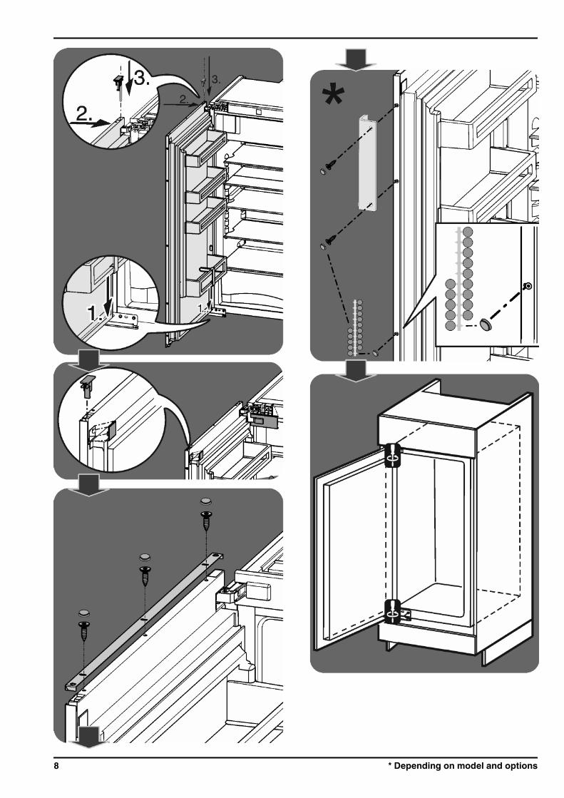
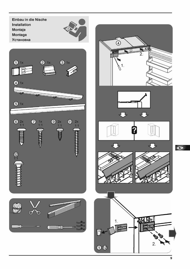
10 Installing the appliance in therecess
WARNINGFire hazard from short-circuiting!u When pushing the appliance into the recess, take care not to
crush, jam or damage the mains power cable.u Do not operate the appliance with a defective mains power
cable.
There is a risk of injury during this stage! Pleaseobserve the safety instructions!The instructions apply to several models. Only carryout this step if the appliance is equipped with thecorresponding feature.Choose between the alternatives given.
Loosen the screws only, do not undo them all the way.
Check the screws and tighten if necessary.
u Please take note of the information in the symbols keyduring installation.
Install the appliance into the recess as shownat the end of the book.
Mount the décor panel with equaliser trim
* Depending on model and options 5

11 Disposing of packaging
WARNINGDanger of suffocation due to packing material and plastic film!u Do not allow children to play with packing material.The packaging is made of recyclable materials:- corrugated board/cardboard- expanded polystyrene parts- polythene bags and sheets- polypropylene straps- nailed wooden frame with polyethylene panel*u Take the packaging material to an official collecting point.
12 Connecting the applianceNOTICEFailure to connect properlyDamage to the electronics.u Do not use a standalone inverter.u Do not use an energy saving plug.
WARNINGFailure to connect properlyFire.u Do not use an extension cable.u Do not use distributor blocks.The type of current (alternating current) and voltage at theinstallation site have to conform with the data on the type plate(see Appliance at a glance).The socket must be properly earthed and fused. The trippingcurrent for the fuse must be between 10 A and 16 A.The socket must be easily accessible so that the appliance canbe quickly disconnected from the supply in an emergency. Itmust be outside the area of the rear of the appliance.u Check the electrical connection.u Plug in the power plug.
Disposing of packaging
6 * Depending on model and options

7
8 * Depending on model and options
9

10 * Depending on model and options

11
Liebherr-Hausgeräte Ochsenhausen GmbHMemminger Straße 77-7988416 OchsenhausenDeutschlandhome.liebherr.com