Florida Board of Governors Student Achievement Subcommittee Paul E. Lingenfelter April 21, 2004

Lingenfelter Performance Engineering1557 Winchester Road
Decatur, IN 46733(260) 724-2552
(260) 724-8761 faxwww.lingenfelter.com
Revision - 2.0 Release date: 18 August 2016
Installation Instructions for the Lingenfelter TBRC-001 Temperature Based Relay Controller
PN: L460220000

Page 1.
Parts ListLPE TBRC-001 Temperature Based Ralay Controller Kit (PN: L460220000)
# Description Part number 1 TBRC-001 Temperature Based Relay Controller L460220000 1 TBRC-001 pigtail harness, 36” XX04851-0003 2 Self tapping screws AV16037 2 Hook and loop tape, per inch 06483 1 Instructions N/A
Tools & Materials Required
Optional Items
• Phillips head screwdriver• Wire crimping tool• Flat head screwdriver - tip size 1/16”
Description Part number Two speed dual fan control harness with relays XX05636-0002 LPE technician’s screwdriver L950050000 LPE sealed 40 amp relay kit L450100000 STOV-004 MPH activated switch (for turning off fans based on VSS) L460340004 Red 7 LED warning light, 10 ft two wire cable RP-WLRBLK001 Sensors and mating connectors See table 4 on page 11.
Specifications:• Works with OEM and aftermarket IAT, ECT, EGT, TFT sensors, including:
• GM IAT (12160244/12614717) • ECT (12608814/12636612) • TFT (12458118)• Oil temperature sensors (15326388)• Bosch 2780071435, 2782569739, 2782650379, 2782610059, 2782412811, 2782334347, 0280130039• AEM30-2012andothersimilarfluidtemperaturesensors
• Works with OEM and aftermarket EGT sensors, including:• AEM 20-3050• GM 12636612• AC Delco 213-4695• Bosch PT 200E• Sensata TS200–A• PT200 RTD
• Built-in Output Cycling Mode.• Used in applications where the temperature sensor is installed in-line with the device.• 16 timer settings available.
• Reduces the audible noise created by auxiliary cooling system components (fans, pumps, etc...) while increasing their life due to the fact that the components are not in constant operation.
• CustommoldedhightemperatureglassfilledNylon6enclosure.• Fully encapsulated (potted) construction for increased durability.• Both outputs can be used simultaneously.• Outputs have a self protect feature and will turn OFF in case of
a direct short or over current condition.• Operating voltage range: 9.0 to 18.0 volts.• Input signal impedance: 100k ohms.• Outputs rated for up to 0.75 amps each.• Current draw: 0.1 amp plus current draw of device being
controlled (when active).• Internal pull-up resistor value: 2.2 k ohms.• 1 Year warranty (from date of purchase).
Figure 1: Sensor circuit with TBRC-001’s internal pull-up resistor.

Page 2.
Thank you for purchasing the Lingenfelter Performance Engineering (LPE) TBRC-001 Temperature Based Relay Controller. The TBRC-001 is designed to control two independent relays based on temperature sensor readings. This module can be used to:
• Independently activate two relays in order to control fans, pumps, or other devices. • This module is used in the LPE intercooler radiator kits to control the two fans at high and low
speeds, and also in the LPE differential cooler kits to control the fan and pump.• Activate intercooler water spray based on air temperature or alcohol injection based on intercooler
temperature.• Activateawarninglightbasedonexhaustgastemperature,transmissionfluidtemperature,oil
temperature, or other temperature readings.• TheseinstructionsarespecificallyfortheRev.“B”versionoftheproductthataddedsupportforthe
Bosch ECT and IAT sensorsTable 1 - Wiring (also labeled on module)
Wire color Label Notes
Red +12V Switched Power Connects to a switched and fused +12 volt DC source.
Black Ground Connects to a vehicle ground.Brown Sensor Ground This wire provides a ground path for the sensor.Purple Sensor Signal This wire connects to the sensor signal output wire.
Gray Relay Output #1 This wire should be connected to a relay used to control components such as an intercooler radiator fan or differential cooler fan. This output provides normally off ground activation.
Yellow Relay Output #2This wire should be connected to a relay used to control components such as an intercooler
radiator fan or differential cooler fan. This output provides normally off ground activation. Use this output for Output Cycling Mode.
Settings:• Controlled by four (4) ten position switches, one (1) sixteen position switch, and
four (4) DIP switches• Two (2) ten position switches for selecting the temperature settings for Relay #1
• Degrees Fahrenheit (in hundreds of degrees)• Degrees Fahrenheit (in tens of degrees)• Possible temperature range of 10-990 degrees Fahrenheit in 10 degree
increments• Two (2) ten position switches for selecting the temperature settings for Relay #2
• Degrees Fahrenheit (in hundreds of degrees)• Degrees Fahrenheit (in tens of degrees)• Possible temperature range of 10-990 degrees Fahrenheit in 10 degree increments• For EGT type sensors (sensor settings of 8, 9, A, or B on TBRC-001), 1000 degrees Fahrenheit is added to the
selected temperature setting. For an EGT type sensor, the possible temperature range is 1000-1990 degrees Fahrenheit in 10 degree increments.
• One (1) sixteen position switch for selecting the sensor type and activation hysteresis
Table 2 - TBRC-001 Sensor and Hysteresis Settings
Type of sensorHysteresis (in F°)
5 10 15 25OEM GM IAT, ECT 0 1 2 3
Setting on 16 position switch
AEM / Autometer 1/8 NPT 4 5 6 7GM / AEM / Bosch / Sensata EGT platinum RTD 8 9 A B
Bosch IAT/ECT sensor C D E F
Power
TBRC-001Temperature Based
Ground - Black
Relay Output #1 - GrayRelay Output #2 - Yellow
Sensor Ground - Brown
Relay Controller
Temp1 x100
Temp1 x10
+12V Switched Power - Red
Relay #1 On Temp
Temp2 x10Temp2 x100Relay #2 On Temp
Sensor Signal - Purple

Page 3.
• Four (4) DIP switches for activating and controlling Output Cycling Mode• Output Cycling Mode is used in applications where the device
that you would like to measure does not have provisions for a temperature sensor. See the Output Cycling Mode section of the instructions on page 4 for further explanation of function and settings.
• DIP switches #1-4 are used to control this setting. DIP switch #5 is inactive and has no effect on the setting. Refer to the rear cover graphiconpage4,whichshowstheavailableconfigurations.
• Output Cycling Mode is only available for relay output #2.
Status LED:• Solid RED when powered up with no temperature sensor detected or with no temperature sensor within the range of
the accepted values.• -35°F to 350°F for IAT or ECT sensors.• -35°F to 2500°F for EGT sensors.
• Solid GREEN when the temperature sensor is detected and within the valid temperature range, but the temperature hasnotreachedtheuser-definedactivationpoint.
• Blinking GREEN when Relay Output #1 is active, but Relay Output #2 is inactive.• Blinking RED when Relay Output #1 is inactive, but Relay Output #2 is active.
• Blinking GREEN+RED when both Relay Output #1 and Relay Output #2 are active.
Installation:• Disconnectthenegativebatteryterminal.• ConnecttheblackwireoftheTBRC-001toasuitablevehicleground.• Connecttheredwiretoaswitched and fused +12 volt DC source. • Connectthebrownwiretothegroundsideofthetemperaturesensor.• Connectthepurplewiretothesensoroutputsignal.Thissignalwillincreaseordecreaseasthetemperature
measured by the sensor increases, depending on the type of sensor used.• Connectthegraywire(Relay#1)totherelaythatcontrolsyourfirstcomponent(suchasafanorapump).• Connect the yellow wire (Relay #2) to the relay that controls your second component.
• If you are using an EGT type sensor and you want to activate a relay above 1000 degrees Fahrenheit, you must connect it to this wire because relay output #2 is the only output that can be set to above 1000 degrees Fahrenheit.
• If using Output Cycling Mode, the device to be cycled must be connected to this output.• Securethedeviceusingthesuppliedhookandlooptapeorusingthesuppliedselftappingscrews.• Setthesixteenpositionswitchtothecorrectsettingforthedesiredsensortypeandhysteresis.RefertotheTable2
on page 2 in order to select the desired setting.• If connecting to a relay through the gray wire, set the desired relay #1 ON temperature using the two (2) ten position
switches labeled “Temp1 x100” and “Temp1 x10”.• If connecting to the relay through the yellow wire, set the desired relay #2 ON temperature using the two (2) ten
position switches labeled “Temp2 x100” and “Temp2 x10”. If the sixteen position switch (sensor type and hysteresis) was set anywhere from ‘8’ to ‘B’, 1000 degrees Fahrenheit will be added to the selected relay #2 ON temperature.

Page
Additional notes / warnings:• Changes to the settings on the TBRC-001 must be done with the ignition off.
• The switch positions are only read when the module is initially powered up.• Do NOT submerge the module in liquid or directly wash the unit with liquid of any type! The switches on the TBRC-
001 are sealed but are NOT rated for high pressure washing, use caution if power washing near the TBRC-001 module. Mount the module where it will not be exposed to constant water.
• Do NOT mount the TBRC-001 directly on top of the engine or near the exhaust manifolds due to heat concerns.• Do NOT mount the TBRC-001 in the line of site of high temperature objects such as exhaust manifolds, turbine
housings etc. If needed, put a heat shield in between the heat source and the module to protect the plastic case.• DoNOTinstallwithin6”ofnitroussolenoidsorotherdeviceswithstrongmagneticfields.• Do NOT install near the spark plugs or the spark plug wires (or other potential strong sources of electrical noise).• LPE recommends the use of resistor type spark plugs and RFI (radio frequency interference) and EMI
(electromagnetic interference) suppression spark plug wires on all EFI engines and any vehicle that has electronic control modules on board (including the TBRC-001). Failure to do so may result in erratic operation of electronic devices including the TBRC-001.
• Do NOT install the TBRC-001 to a sensor that is already being used by another device. This will cause the TBRC-001 and the other device to inaccurately read the temperature.
Output Cycling ModeIf it is desired to measure the temperature inside a device that does not have provisions for a temperature sensor, the only solution may be to put the temperature sensor inline with the device. If the temperature sensor must be installed in the fluidlinesconnectedtothedevice,theTBRC-001’sOutputCyclingModecanbeusedtocirculatehotfluidpastthesensor(i.e.youwanttocyclethepumptogetthehotfluidoutofthedifferentialortransmissionandpastthesensorsoyoucandeterminethetemperatureofthefluidinthedifferentialortransmission).WhileinOutputCyclingMode,severalcyclerateand duration settings are available.
To change cycle rate and duration settings: • Use a #1 Phillips head screwdriver to remove the back cover of the unit.• On the inside of the unit’s back cover, there is a sticker that shows the possible cycle rate and duration settings, as
wellasthecorrectDIPswitchconfigurationforeachone.Thisgraphicisshown on the right.
• Usingasmallflatheadscrewdriver,flipthecorrectDIPswitchesONorOFFto select the desired cycle rate and duration.• Setting examples:
• To deactivate Output Cycling Mode, set the DIP switches to setting #0 (↓↓↓↓↓)
• In order to activate output #2 for 15 seconds every 5 minutes, set the DIP switches to setting #4 (↓↓↑↓↓).
• In order to activate output #2 for 30 seconds every 10 minutes, set the DIP switches to setting #8 (↓↓↓↑↓).
• In order to activate output #2 for 1 minute every 15 minutes, set the DIP switches to setting #12 (↓↓↑↑↓). • Replace and secure the rear cover plate to the back of the TBRC-001.• Powerupthedevicetofinalizethechangestothecyclerateandduration.
4.
1 2 3 4 5 ON OFF0123456789
101112
151413
0 = TIMER OFF1 MIN. DELAY, 5 SEC. ON1 MIN. DELAY, 15 SEC. ON5 MIN. DELAY, 5 SEC. ON5 MIN. DELAY, 15 SEC. ON5 MIN. DELAY, 30 SEC. ON10 MIN. DELAY, 5 SEC. ON10 MIN. DELAY, 15 SEC. ON10 MIN. DELAY, 30 SEC. ON15 MIN. DELAY, 5 SEC. ON15 MIN. DELAY, 15 SEC. ON15 MIN. DELAY, 30 SEC. ON15 MIN. DELAY, 1 MIN. ON20 MIN. DELAY, 15 SEC. ON20 MIN. DELAY, 30 SEC. ON20 MIN. DELAY, 1 MIN. ON
Figure 2: DIP switch settings
(This graphic can also be found under the back cover of the TBRC-001)

Page 5.
Using the TBRC-001 to activate two independent fans based on ECT sensor output
Using the TBRC-001 to activate a warning light based on IAT, EGT, or ECT sensor output
To switched and fused 12v power
85
86
30
87a 87
To switched and fused 12v power
IAT, ECT, or EGT Sensor
Relay is required if warning light pulls
more than .75 amps
Power
TBRC-001Temperature Based
Ground - Black
Relay Output #1 - GrayRelay Output #2 - Yellow
Sensor Ground - Brown
Relay Controller
Temp1 x100
Temp1 x10
+12V Switched Power - Red
Relay #1 On Temp
Temp2 x10Temp2 x100Relay #2 On Temp
Sensor Signal - Purple
To Ground
To relay output #1 (if needed for
second device)
To Ground
WarningLight
To switched and fused 12v power
To switched and fused 12v power
85
86
30
87a 87
85
86
30
87a 87
To switched and fused 12v power
To switched and fused 12v power
To Ground
To Ground
ECT Sensor
Fan #1 Control Relay
Fan #2 Control Relay
Fan #2 Fan #1
Power
TBRC-001Temperature Based
Ground - Black
Relay Output #1 - GrayRelay Output #2 - Yellow
Sensor Ground - Brown
Relay Controller
Temp1 x100
Temp1 x10
+12V Switched Power - Red
Relay #1 On Temp
Temp2 x10Temp2 x100Relay #2 On Temp
Sensor Signal - Purple
To Ground
To switched and fused 12v power
To switched and fused 12v power
Quantity Component Part Number
1 TBRC-001 L460220000
1 ECT sensor refer to pg. 11
2 *40 amp relay L450100000
Quantity Component Part Number
1 TBRC-001 L460220000
1 ECT sensor refer to pg. 11
1 40 amp relay L450100000
1 warning light RP-WLRBLK001
*a higher capacity relay may be required, please refer to the manufacturer for your
specificproductrequirements

Page
To switched and fused
12v power
To switched and fused 12v power
ECT Sensor
Power
TBRC-001Temperature Based
Ground - Black
Relay Output #1 - GrayRelay Output #2 - Yellow
Sensor Ground - Brown
Relay Controller
Temp1 x100
Temp1 x10
+12V Switched Power - Red
Relay #1 On Temp
Temp2 x10Temp2 x100Relay #2 On Temp
Sensor Signal - Purple
To Ground
To Ground
Fan #2
To switched and fused 12v power
To switched and fused(10A) 12v
power
85
86
30
87a 87
85
86
30
87a87
85
86
30
87a 87
Fan #1
6.
Using the TBRC-001 to activate two fans at two speeds (LOW or HIGH) based on ECT sensor output
The fans that operate at two speeds run from parallel to series. This causes a variation in voltage supplied to the fans. In this case, the voltage that goes to the fans is either 6V or 12V. Some fans may not operate well at 6V. Verify that the fan(s)youareusingareabletooperateat6Vfromthefanmanufacturer.Thesettingsforthenextfiveexamplesareasfollows: Temp1 is set to 90 degrees; Temp2 is set to 100 degrees; and 10 degrees is set for the hysteresis for a OEM GM type sensor.• As the temperature warms up, the fan(s) turn(s) on low speed at 90 degrees F.• The fan(s) turn(s) on high speed at 110 degrees F.• As the temperature cools the fan(s) should go back to low speed at 100 degrees F.• The fan(s) should turn back off at 80 degrees F.
Quantity Component Part Number
1 TBRC-001 L460220000
1 ECT sensor refer to pg. 11
3 *40 amp relay L450100000*a higher capacity relay may be required, please refer to the manufacturer for your
specificproductrequirements

Page
To Ground
To switched and fused 12v power
To switched and fused
12v power
To Ignition To Ignition
85
86
30
87a 87
85
86
30
87a 87
Fan High Fan Low
To Ground
ECT Sensor
Power
TBRC-001Temperature Based
Ground - Black
Relay Output #1 - GrayRelay Output #2 - Yellow
Sensor Ground - Brown
Relay Controller
Temp1 x100
Temp1 x10
+12V Switched Power - Red
Relay #1 On Temp
Temp2 x10Temp2 x100Relay #2 On Temp
Sensor Signal - Purple
Using the TBRC-001 to activate a two speed fan based on ECT sensor output
7.
Quantity Component Part Number
1 TBRC-001 L460220000
1 ECT sensor refer to pg. 11
2 *40 amp relay L450100000
*a higher capacity relay may be required, please refer to the manufacturer for your
specificproductrequirements

Page 8.
Using the TBRC-001 in conjunction with a Volvo or similar cooling fan relay to activate a two speed fan
based on ECT sensor output
To Ground
To switched and fused 12v power
To fused 12v power
To Ground
Output
2 1
Input
2 1 +12V
Volvo Relay / Fan Control
Fan High
Fan Low
ECT Sensor
Power
TBRC-001Temperature Based
Ground - Black
Relay Output #1 - GrayRelay Output #2 - Yellow
Sensor Ground - Brown
Relay Controller
Temp1 x100
Temp1 x10
+12V Switched Power - Red
Relay #1 On Temp
Temp2 x10Temp2 x100Relay #2 On Temp
Sensor Signal - Purple
The following Volvo OEM parts for the Volvo Cooling Fan Relay 2-SPD: Volvo OE: 9442933, 1398845, 3523872.Kaehler also manufactures a part that is similiar to the Volvo Cooling Fan Relay. The part number is KAE 3702300.
The “Volvo” name is property of the Volvo Car Corporation
Quantity Component Part Number
1 TBRC-001 L460220000
1 ECT sensor refer to pg. 11
1 *Volvo relay
*see table below for applicable Volvo relays. Ensure your relay has the capacity for the fan it
will activate

Page 9.
Using the TBRC-001 and STOV-004 to activate two fans at two fan speeds (LOW or HIGH)
based on ECT and VSS sensor outputUsing the wiring diagram below, the fans are based on temperature as well as the speed of the vehicle. The STOV-004 in thisdiagramutilizesthe+12VOutputNormallyONfunction.Whatthisdoesisswitchthe+12VOutputNormallyOFFtoNormally ON, switch the ground output that is Normally OFF to Normally ON, and switch the ground output that is Nor-mally ON to Normally OFF. To set the +12V output to be normally on, set both of the MPH Low rotary switches to 0 and then set the desired switch point speed using the MPH High rotary switches. The x1 switch controls the speed setting in 1 MPH increments and the x10 switch controls the speed setting in 10 MPH increments. In this example, the STOV-004 in the diagram is set to 60 MPH on MPH High. This means that if the MPH of the vehicle exceeds 60 MPH the fans will not be active regardless of what the temperature reading is.
To switched and fused
12v power
To switched and fused 12v power
ECT Sensor
Power
TBRC-001Temperature Based
Ground - Black
Relay Output #1 - GrayRelay Output #2 - Yellow
Sensor Ground - Brown
Relay Controller
Temp1 x100
Temp1 x10
+12V Switched Power - Red
Relay #1 On Temp
Temp2 x10Temp2 x100Relay #2 On Temp
Sensor Signal - Purple
To Ground
To Ground
Fan #2
To switched and fused 12v power
85
86
30
87a 87
85
86
30
87a87
85
86
30
87a 87
Fan #1
To Switched and fused 12v power
To Ground
To VSSPower
STOV-004VSS Switch &
Speed to VoltageConverter
Ground - Black
Normally On - GrayNormally Off - Yellow
MPH Low x10
MPH Low x1
+12V Switched Power - Red
MPH Low
MPH High x10MPH High x1MPH High
Analog Output Signal - Blue
+12V Output Norm Off - Orange
VSS Input Signal - White
Function Select
Quantity Component Part Number
1 TBRC-001 L460220000
1 STOV-004 L460340004
1 ECT sensor refer to pg. 11
3 *40 amp relay L450100000
*a higher capacity relay may be required, please refer to the manufacturer for your
specificproductrequirements

Page
Temperature
Temperature sensor type (settings group on TBRC-001)
GM ECT/IAT/TFT (use settings 0-3)
AEM / Autometer 1/8 NPT
(use settings 4-7)
GM / AEM / Bosch / Sensata EGT Platinum RTD
(use settings 8-B)
Bosch IAT/ECT Sensor Group (settings C-F)
°C °F Resistance values measured in Ohms-40 -40 100700 402000 170 45,313-30 -22 52700 210000 178 26114-20 -4 28680 114000 185 15462-10 14 16180 64300 193 93970 32 9420 37500 201 5896
10 50 5670 22500 208 379220 68 3520 14000 216 250030 86 2238 8900 224 170740 104 1459 5800 231 117550 122 973 3900 239 83460 140 667 2700 246 59670 158 467 1900 254 43680 176 332 1300 261 32390 194 241 965 268 243100 212 177 710 276 187110 230 132 531 284 144120 248 100 403 291 113130 266 77 309 299 89140 284 60 241 306 71150 302 47 189 313 57200 392 - - 349 -300 572 - - 420 -400 752 - - 488 -500 932 - - 554 -600 1112 - - 618 -700 1292 - - 679 -800 1472 - - 738 -900 1652 - - 795 -
1000 1832 - - 849 -
Table 3: Temperature Sensor Resistance vs. Temperature
• All resistance values shown above are approximate and will be different based on which specifictemperaturesensoryouuse.Alsokeepinmindthatmostofthesesensorsarerated to within +/- 3% to 5% variation from sensor to sensor so the above tables are not exact.
10.
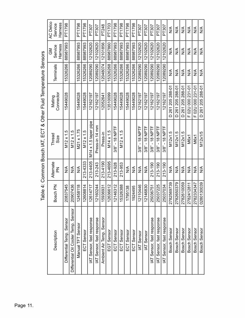
Page
Des
crip
tion
Bos
ch P
NA
ltern
ate
PN
Thre
adSize
Mat
ing
Con
nect
orTe
rmin
als
GM
S
ervi
ce
Har
ness
AC
Del
co
Ser
vice
H
arne
ssD
iffer
entia
l Tem
p. S
enso
r20
8375
45N
/AM
12 x
1.5
1544
9028
1532
6266
8898
7993
PT1
798
Diff
eren
tial O
il C
oole
r Tem
p. S
enso
r20
9074
36N
/AM
12 x
1.5
Man
ual T
FT S
enso
r12
4581
18N
/AM
21 x
1.7
515
4490
2815
3262
6688
9879
93P
T179
8E
CT
Sen
sor
1260
8814
213-
4333
M12
x 1
.515
4490
2815
3262
6688
9879
93P
T179
8IA
T S
enso
r, fa
st re
spon
se12
6147
1721
3-44
05M
14 x
1.5
tape
r pip
e12
1621
9712
0892
9012
1026
20P
T307
IAT
Sen
sor,
fast
resp
onse
1216
0244
213-
243
Pre
ss-in
14
mm
1216
2197
1208
9290
1210
2620
PT3
07A
mbi
ent A
ir Te
mp.
Sen
sor
1593
6931
213-
4190
Pre
ss-in
1205
2641
1204
8074
1210
1856
PT2
48E
GT
Sen
sor
1263
6612
213-
4695
M14
x 1
.513
5100
9915
3262
6888
9878
60P
T170
3E
CT
Sen
sor
1214
6312
213-
928
3/8”
- 18
NP
TF15
4490
2815
3262
6688
9879
93P
T179
8E
CT
Sen
sor
1532
6388
213-
953
M12
x 1
.515
4490
2815
3262
6688
9879
93P
T179
8E
CT
Sen
sor
1795
138
N/A
1544
9028
1532
6266
8898
7993
PT1
798
EC
T S
enso
r19
2449
5N
/A15
4490
2815
3262
6688
9879
93P
T179
8IA
T S
enso
r12
1104
46N
/A3/
8” -
18 N
PTF
1216
2197
1208
9290
1210
2620
PT3
07IA
T S
enso
r12
1468
30N
/A3/
8” -
18 N
PTF
1216
2197
1208
9290
1210
2620
PT3
07IA
T S
enso
r, fa
st re
spon
se25
0367
5121
3-19
03/
8” -
18 N
PTF
1216
2197
1208
9290
1210
2620
PT3
07IA
T S
enso
r, fa
st re
spon
se25
0372
2521
3-19
03/
8” -
18 N
PTF
1216
2197
1208
9290
1210
2620
PT3
07IA
T S
enso
r, fa
st re
spon
se25
0370
3421
3-19
03/
8” -
18 N
PTF
1216
2197
1208
9290
1210
2620
PT3
07B
osch
Sen
sor
2782
5697
39N
/AM
12x1
.5D
261
205
288
-01
N/A
N/A
N/A
Bos
ch S
enso
r27
8265
0379
N/A
M12
x1.5
D 2
61 2
05 2
88-0
1N
/AN
/AN
/AB
osch
Sen
sor
2782
6100
59N
/AM
12x1
.5D
261
205
288
-01
N/A
N/A
N/A
Bos
ch S
enso
r27
8241
2811
N/A
M6x
1F
02U
000
231
-01
N/A
N/A
N/A
Bos
ch S
enso
r27
8233
4347
N/A
M6x
1F
02U
000
231
-01
N/A
N/A
N/A
Bos
ch S
enso
r02
8013
0039
N/A
M12
x1/5
D 2
61 2
05 2
88-0
1N
/AN
/AN
/A
Tabl
e 4:
Com
mon
Bos
ch IA
T, E
CT
& O
ther
Flu
id T
empe
ratu
re S
enso
rs
11.

Page 12.
1557 Winchester RoadDecatur, Indiana 46733 (260) 724-2552 phone
(260) 724-8761 faxwww.lingenfelter.com
L460220000 TBRC-001 Rev B temperature based relay controller v2.0.indd
TroubleshootingIf you believe that the TBRC-001 is switching at an incorrect temperature, check the following:• Use a multimeter to measure the sensor’s resistance at a certain temperature. Compare the measured resistance to
the resistance values on the sensor type vs. sensor resistance chart on page 11.• Check to verify that you have set the 16 position (sensor type and hysteresis) switch to the correct range for your
sensor type.• Make sure no other device is connected to the temperature sensor you are using
NOTICES:It is the responsibility of the purchaser to follow all guidelines and safety procedures supplied with this product and any other manufacturer’s product used with this product.Lingenfelter Performance Engineering assumes no responsibility for damages resulting from accident, improper installation, misuse, abuse, improper operation, lack of reasonable care, or all previously stated reasons due to incompatibility with other manufacturer’s products.Lingenfelter Performance Engineering assumes no responsibility or liability for damages incurred from the use of products manufactured or sold by Lingenfelter Performance Engineering on vehicles used for competition racing.It is the purchaser’s responsibility to check the state and local laws and sanctioning body requirements pertaining to the use of this product for racing applications. Lingenfelter Performance Engineering does not recommend nor condone the use of its products for illegal street racing.
Limited Warranty:LPE warrants the Lingenfelter TBRC-001 Temperature Based Relay Controller to be free from defects in material and workmanship under normal use and if properly installed for a period of 1 year from date of purchase. If the module is found to be defective as mentioned above, it will be replaced or repaired if returned prepaid along with proof of date of purchase. This shall constitute the sole remedy of the purchaser and the sole liability of LPE. To the extent permitted by law, the foregoing is exclusive and in lieu of all other warranties or representations whether expressed or implied, includinganyimpliedwarrantyofmerchantabilityorfitness.InnoeventshallLPEbeliableforspecialorconsequentialdamages.
For additional product installation information and technical support, contact LPE or your LPE products distributor.YoucanalsofindtechnicalsupportandusagediscussionsregardingthisproductandmanyotherLPE products in our Internet forums:
http://www.lingenfelter.com/forum_lingenfelter/index.php
Follow us on Facebook!
http://www.facebook.com/home.php#!/lpehp