Installation Instructions for NC-2 Progressive Nitrous ...
18
Daytona Sensor, 240 Springview Commerce Dr, Bldg 1-J, Debary, FL 32713 NC-2 (386) 322-7390 www.daytona-sensors.com 8/2021 Page 1 Installation Instructions for NC-2 Progressive Nitrous Controller and Vehicle Data Logger CAUTION: CAREFULLY READ INSTRUCTIONS BEFORE PROCEEDING. NOT LEGAL FOR SALE OR USE IN CALIFORNIA OR ON ANY POLLUTION CONTROLLED VEHICLES. OVERVIEW The NC-2 is a combination progressive nitrous controller and vehicle data logger with the following features: Controls two nitrous stages and purge solenoid. 40 amp output drive capability on each nitrous stage. Each stage is independently programmable based on throttle position, RPM, vehicle speed, time delay, and first gear lockout. Progressive control based on RPM or time. Programmable automatic purge when system is armed. Flexible RPM input compatible with high level coil drive (vehicles with coil packs or distributor ignition), standard 12V tach signal, or low level logic drive (newer vehicles with coil-on-plug). General purpose input/output (GPIO) terminal. Programmable for use as shift light output, additional stage enable input, or control output for ignition retard. Status LED output (ideal for use with arming switch containing LED). Built-in data logging. Ideal as basic vehicle data logger during dyno tuning or drag racing. Logs data whenever system is armed. Stores last 5 minutes of data at 10 samples/second. Data logged includes throttle position, RPM, vehicle speed, status of all inputs and outputs, and two 0-5V analog inputs. 0-5V analog inputs are compatible with Daytona Sensors single or dual channel WEGO systems for logging wide-band air/fuel ratio data. Heavy duty industrial grade clamping terminal blocks allow easy and reliable hookup without soldering or crimping. Compact size: is 4.1”L x 2.8”W x 1.1”H (not including mounting feet and terminal block). USB interface to laptop PC. Powerful Windows software for programming controller and downloading logged data. Figure 1 – NC-2 Nitrous Controller ADDITIONAL REQUIRED PARTS The NC-2 comes with a USB cable. To complete the installation, you will require: wire, wire labels, crimp terminals, fuses, switches, and relays. If you are adding the NC-2 to an existing nitrous system installation, you may already have most of these items but some rewiring may be required. The Appendix includes a list of recommended parts and suppliers. Throttle position sensor (TPS), RPM, and vehicle speed sensor (VSS) signal connections are required to utilize all the capabilities of the NC-2. You will require a vehicle wiring diagram to locate these signal connections. INSTALLATION 1. Turn off the ignition switch and disconnect the battery ground cable before proceeding. 2. Select a convenient mounting location for the NC-2. The unit is not sealed and must be mounted in a dry location away from sources of heat. We recommend underdash mounting. The unit is not intended for underhood mounting. You can secure the NC-2 with two sheet metal screws or Velcro tape strips. Orient the unit so that you will have easy access to the terminal blocks and USB port.
Transcript of Installation Instructions for NC-2 Progressive Nitrous ...

Daytona Sensor, 240 Springview Commerce Dr, Bldg 1-J, Debary, FL 32713 NC-2 (386) 322-7390 www.daytona-sensors.com 8/2021
Page 1
Installation Instructions for NC-2 Progressive Nitrous Controller and Vehicle Data Logger
CAUTION: CAREFULLY READ INSTRUCTIONS BEFORE PROCEEDING. NOT LEGAL FOR SALE OR USE IN CALIFORNIA OR ON ANY POLLUTION CONTROLLED VEHICLES.
OVERVIEW The NC-2 is a combination progressive nitrous
controller and vehicle data logger with the following features:
Controls two nitrous stages and purge solenoid. 40 amp output drive capability on each nitrous stage.
Each stage is independently programmable based on throttle position, RPM, vehicle speed, time delay, and first gear lockout. Progressive control based on RPM or time.
Programmable automatic purge when system is armed.
Flexible RPM input compatible with high level coil drive (vehicles with coil packs or distributor ignition), standard 12V tach signal, or low level logic drive (newer vehicles with coil-on-plug).
General purpose input/output (GPIO) terminal. Programmable for use as shift light output, additional stage enable input, or control output for ignition retard.
Status LED output (ideal for use with arming switch containing LED).
Built-in data logging. Ideal as basic vehicle data logger during dyno tuning or drag racing. Logs data whenever system is armed. Stores last 5 minutes of data at 10 samples/second.
Data logged includes throttle position, RPM, vehicle speed, status of all inputs and outputs, and two 0-5V analog inputs.
0-5V analog inputs are compatible with Daytona Sensors single or dual channel WEGO systems for logging wide-band air/fuel ratio data.
Heavy duty industrial grade clamping terminal blocks allow easy and reliable hookup without soldering or crimping.
Compact size: is 4.1”L x 2.8”W x 1.1”H (not including mounting feet and terminal block).
USB interface to laptop PC. Powerful Windows software for programming controller and downloading logged data.
Figure 1 – NC-2 Nitrous Controller
ADDITIONAL REQUIRED PARTS The NC-2 comes with a USB cable. To complete
the installation, you will require: wire, wire labels, crimp terminals, fuses, switches, and relays. If you are adding the NC-2 to an existing nitrous system installation, you may already have most of these items but some rewiring may be required. The Appendix includes a list of recommended parts and suppliers.
Throttle position sensor (TPS), RPM, and vehicle speed sensor (VSS) signal connections are required to utilize all the capabilities of the NC-2. You will require a vehicle wiring diagram to locate these signal connections.
INSTALLATION 1. Turn off the ignition switch and disconnect the
battery ground cable before proceeding.
2. Select a convenient mounting location for the NC-2. The unit is not sealed and must be mounted in a dry location away from sources of heat. We recommend underdash mounting. The unit is not intended for underhood mounting. You can secure the NC-2 with two sheet metal screws or Velcro tape strips. Orient the unit so that you will have easy access to the terminal blocks and USB port.

Daytona Sensor, 240 Springview Commerce Dr, Bldg 1-J, Debary, FL 32713 NC-2 (386) 322-7390 www.daytona-sensors.com 8/2021
Page 2
Figure 2 – Basic Hookup

Daytona Sensor, 240 Springview Commerce Dr, Bldg 1-J, Debary, FL 32713 NC-2 (386) 322-7390 www.daytona-sensors.com 8/2021
Page 3
Figure 3 – Hookup for Independent Control of Nitrous and Fuel Flow
Daytona Sensor, 240 Springview Commerce Dr, Bldg 1-J, Debary, FL 32713 NC-2 (386) 322-7390 www.daytona-sensors.com 8/2021
Page 4
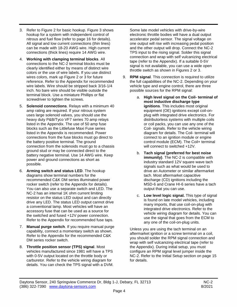
3. Refer to Figure 2 for basic hookup. Figure 3 shows hookup for a system with independent control of nitrous and fuel flow (refer to page 16 for details). All signal and low current connections (thin lines) can be made with 18-20 AWG wire. High current connections (thick lines) require 14 AWG wire.
4. Working with clamping terminal blocks. All connections to the NC-2 terminal blocks must be clearly identified either by means of distinct wire colors or the use of wire labels. If you use distinct wires colors, mark up Figure 2 or 3 for future reference. Refer to the Appendix for recommended wire labels. Wire should be stripped back 3/16-1/4 inch. No bare wire should be visible outside the terminal block. Use a miniature Phillips or flat screwdriver to tighten the screws.
5. Solenoid connections. Relays with a minimum 40 amp rating are required. If your nitrous system uses large solenoid valves, you should use the heavy duty P&B/Tyco VF7 series 70 amp relays listed in the Appendix. The use of 50 amp fuse blocks such as the Littlefuse Maxi Fuse series listed in the Appendix is recommended. Power connections from the fuse blocks must go direct to the battery positive terminal. The ground connection from the solenoids must go to a chassis ground stud or may be connected direct to the battery negative terminal. Use 14 AWG wire. Keep power and ground connections as short as possible.
6. Arming switch and status LED. The hookup diagrams show terminal numbers for the recommended C&K DM series illuminated power rocker switch (refer to the Appendix for details). You can also use a separate switch and LED. The NC-2 has an internal 1K ohm current limiting resistor on the status LED output and can directly drive any LED. The status LED output cannot drive a conventional lamp. Most vehicles will have an accessory fuse that can be used as a source for the switched and fused +12V power connection. Refer to the Appendix for recommended fuse taps.
7. Manual purge switch. If you require manual purge capability, connect a momentary switch as shown. Refer to the Appendix for the recommended C&K DM series rocker switch.
8. Throttle position sensor (TPS) signal. Most vehicles manufactured since 1981 will have a TPS with 0-5V output located on the throttle body or carburetor. Refer to the vehicle wiring diagram for details. You can check the TPS signal with a DVM.
Some late model vehicles with drive-by-wire electronic throttle bodies will have a dual output accelerator pedal sensor. The signal voltage on one output will rise with increasing pedal position and the other output will drop. Connect the NC-2 TPS input to the rising signal. Solder this signal connection and wrap with self vulcanizing electrical tape (refer to the Appendix). If a suitable 0-5V signal is not available, you can use a wide open throttle switch as shown in Figures 2 or 3.
9. RPM signal. This connection is required to utilize the full capabilities of the NC-2. Depending on your vehicle type and engine control, there are three possible sources for the RPM signal:
a. High level signal on the Coil- terminal of most inductive discharge type ignitions. This includes most original equipment (OE) ignitions except coil-on-plug with integrated drive electronics. For distributorless systems with multiple coils or coil packs, you can use any one of the Coil- signals. Refer to the vehicle wiring diagram for details. The Coil- terminal will connect to an ignition module or engine control module (ECM). The Coil+ terminal will connect to switched +12V.
b. Tach signal (preferred for best noise immunity). The NC-2 is compatible with industry standard 12V square wave tach signals such as what would be used to drive an Autometer or similar aftermarket tach. Most aftermarket capacitive discharge (CD) ignitions including the MSD-6 and Crane HI-6 series have a tach output that you can use.
c. Low level logic signal. This type of signal is found on late model vehicles, including many imports, that use coil-on-plug with integrated drive electronics. Refer to the vehicle wiring diagram for details. You can use the signal that goes from the ECM to any one of the coil-on-plug units.
Unless you are using the tach terminal on an aftermarket ignition or a screw terminal on a coil, you should solder the RPM signal connection and wrap with self vulcanizing electrical tape (refer to the Appendix). During initial setup, you must configure an RPM signal level jumper inside the NC-2. Refer to the Initial Setup section on page 15 for details.

Daytona Sensor, 240 Springview Commerce Dr, Bldg 1-J, Debary, FL 32713 NC-2 (386) 322-7390 www.daytona-sensors.com 8/2021
Page 5
Figure 4 – GPIO Hookup Options
10. Vehicle speed sensor (VSS) signal. This connection is required to utilize the full capabilities of the NC-2. Most vehicles manufactured since 1981 will have a VSS. Refer to the vehicle wiring diagram for details. Some late model vehicles with anti-skid braking (ABS) and electronic stability control (ECS) systems utilize individual wheel sensors use to calculate an average vehicle speed. Accessing a discrete vehicle speed signal on these systems may not be possible. You may have to install a driveshaft sensor (contact tech support for details). For Nissan 350Z applications, you can access vehicle speed on the 8P/R signal (pin 26 on the unified meter and A/C amp module behind the center console).
11. Optional general purpose input/output (GPIO) signal. Refer to Figure 4 for GPIO hookup options. If you use the GPIO to drive a shift light, you must use an 12V LED type. The GPIO cannot drive a conventional lamp. If you use the GPIO to retard an aftermarket ignition that
requires a 12V (active high) signal, you must use a relay as shown. Refer to the Appendix for recommended relays.
12. Optional analog input signals. The NC-2 will log 0-5V data on two analog inputs. Uses include logging air/fuel ratio from a wide-band sensor system such as the Daytona Sensors WEGO IIID shown in Figure 5. The Nitrous Log software is used to set the units and scaling for the analog inputs. Refer to the Nitrous Log section for details.
13. Ground connections. Use 18 AWG wire for the signal ground and two 14 AWG wires for the power ground. Keep the ground connections as short as possible. The ground connections must go to a chassis ground stud (you can usually find one under the dash). If you are using the analog inputs, use the same ground point for any associated devices in order to avoid signals errors due to a ground loop.
14. Reconnect the battery ground cable.

Daytona Sensor, 240 Springview Commerce Dr, Bldg 1-J, Debary, FL 32713 NC-2 (386) 322-7390 www.daytona-sensors.com 8/2021
Page 6
Figure 5 – Analog Input Hookup to Daytona Sensors WEGO IIID Wide-Band System
OVERVIEW OF INITIAL SETUP
The NC-2 requires initial setup to establish nitrous system control parameters. PC Link Nitrous software is used for setup. In addition, the Nitrous Log data logging software is used to check for proper scaling of the throttle position, RPM, and vehicle speed inputs. Complete the software installation and read the software sections of this instruction manual, then continue the initial setup steps on page 15.
PC REQUIREMENTS The NC-2 connects to your PC by means of a
USB interface. A USB cable is supplied with the unit. The PC must have a free USB port. If you have an older PC without USB capability, you cannot use the NC-2.
We recommend a laptop PC with Pentium processor and super VGA display (SVGA with 1024 x 768 pixel resolution) running Windows XP/Vista/7. Data chart display is graphics intensive and a high speed Pentium processor is recommended. Processors slower than 300 MHz will exhibit sluggish program loading and response.
PC Link Nitrous and Nitrous Log software include print commands to print downloaded data. The programs have been tested with Hewlett-Packard laser and inkjet printers and Epson inkjet printers. We recommend using a color inkjet printer.
USB INSTALLATION The USB interface for the NC-2 is based on the
FTDI FT232R chip and drivers that allow the unit to emulate a standard Windows RS-232 COM port. Updated Windows drivers, installation instructions and
Daytona Sensor, 240 Springview Commerce Dr, Bldg 1-J, Debary, FL 32713 NC-2 (386) 322-7390 www.daytona-sensors.com 8/2021
Page 7
troubleshooting tips are available on the FTDI website at www.ftdichip.com. Additional information and troubleshooting tips can be found on the PC Link Tech FAQ on our website at www.daytona-sensors.com.
A new USB driver that simplifies the installation process is available. This installs as an executable file, similar to other Windows programs. The Windows Found New Hardware Wizard will then detect the USB device when it is first connected and automatically install the correct driver without the user having to browse.
Before proceeding with installation, shutdown any other applications that may be running. For Windows Vista, you must disable the User Account Control (UAC) during installation. If you are not familiar with the UAC, please refer to the Vista UAC Tech Note on our website's PC Link Tech FAQ for details.
1. Make sure the unit is not connected to your PC.
2. From the Website under Tech Center, click on Software. Scroll down and click on the USB Driver link. When the File Download dialog box appears, click on "Run this program from its current location." Ignore any security warnings and click on Yes to continue.
3. After installation of the driver is complete, connect the unit to the PC with the supplied USB cable. The Windows Found New Hardware Wizard will appear and complete installation of the USB interface.
COM Port Configuration
After completing the installation steps outlined above, you must configure the new COM port using Device Manager.
1. Windows XP: click Start, Settings, Control Panel, System, Hardware, and then Device Manager. Windows Vista: click Start, Control Panel, System and Maintenance, and then Device Manager. Windows 7: Click Start, Control Panel, System and Security, and then Device Manager. For more information, visit www.pcsupport.about.com.
2. Scroll down to Ports (COM and LPT). The new unit will appear as a USB Serial Port. Click on this new port. Click on the Port Settings tab.
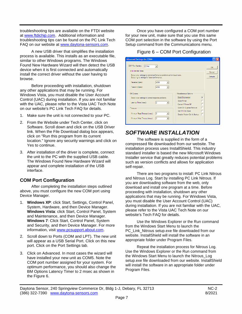
3. Click on Advanced. In most cases the wizard will have installed your new unit as COM5. Note the COM port number assigned for your system. For optimum performance, you should also change the BM Options Latency Timer to 2 msec as shown in the Figure 6.
Once you have configured a COM port number for your new unit, make sure that you use this same COM port selection in the software by using the Port Setup command from the Communications menu.
Figure 6 – COM Port Configuration
SOFTWARE INSTALLATION The software is supplied in the form of a
compressed file downloaded from our website. The installation process uses InstallShield. This industry standard installer is based the new Microsoft Windows Installer service that greatly reduces potential problems such as version conflicts and allows for application self-repair.
There are two programs to install: PC Link Nitrous and Nitrous Log. Start by installing PC Link Nitrous. If you are downloading software from the web, only download and install one program at a time. Before proceeding with installation, shutdown any other applications that may be running. For Windows Vista, you must disable the User Account Control (UAC) during installation. If you are not familiar with the UAC, please refer to the Vista UAC Tech Note on our website's Tech FAQ for details.
Use the Windows Explorer or the Run command from the Windows Start Menu to launch the PC_Link_Nitrous setup.exe file downloaded from our website. InstallShield will install the software in an appropriate folder under Program Files.
Repeat the installation process for Nitrous Log. Use the Windows Explorer or the Run command from the Windows Start Menu to launch the Nitrous_Log setup.exe file downloaded from our website. InstallShield will install the software in an appropriate folder under Program Files.

Daytona Sensor, 240 Springview Commerce Dr, Bldg 1-J, Debary, FL 32713 NC-2 (386) 322-7390 www.daytona-sensors.com 8/2021
Page 8
Once InstallShield has completed the installation, PC Link Nitrous and Nitrous Log will appear on the Windows Start Menu. You can then launch them just as you would any other Windows program.
The programs require the Monospace 821 BT fixed pitch printer font in order to properly align columns when printing. The Monospace 821 BT font is included in the distribution media and automatically copied to your Windows Fonts folder during installation. A backup copy is also placed in the program folder. If you accidentally delete this font, use the Install New Font command from the Fonts folder File menu. The filename associated with Monospace 821 BT is monos.ttf.
PC LINK NITROUS SOFTWARE Before the NC-2 is armed, you can download or
upload data with PC Link Nitrous.
After PC Link Nitrous is launched, the main screen appears blank. When launched for the first time, the program uses COM1 as the default port. In most cases, you will have configured the NC-2 USB interface to use a different COM port, such as COM5. Use the Port Setup command on the Communications menu to select the correct COM port. The program will remember the new port setup.
You have two options for obtaining data for editing. You can open a previously saved setup file by using the Open File command on the File menu or you can download data from an attached NC-2 unit by using the Download Data From EEPROM command on the Communications menu. Note that NC-2 setup files use a .dat extension. You should create a separate folder to store these files. A sample setup file (Sample.dat) is included in the program folder.
Once you have NC-2 data, you can edit various parameters, general setup options, and controller scale factors. You can print the displayed NC-2 setup data by using the Print Parameters command from the File menu. When you open a file or download data from an NC-2 unit, the data is stored in a buffer memory. Once you have completed all your edits, you can save the data in buffer memory to a file or upload it back to the NC-2 by using the appropriate command from the File or Communications menu.
CONTROLLER SCALE FACTORS Controller scale factors shown in Figure 7 are
generally established during initial setup (see page 15) and with the exception of the data logging interval will probably remain unchanged for a particular vehicle. Scale factors that you can set include:
RPM Pulses/Rev – RPM pulses per revolution (PPR). Some general guidelines follow, based on the type of signal connected to the NC-2 RPM input:
Tach signal. This includes aftermarket CD type ignitions with a tach output. In most cases PPR= N/2 where N is the number of cylinders. For example a 4 cylinder engine would require PPR=2 and a V8 engine would require PPR=4
Distributor type ignition with connection to Coil- terminal. Same as for a tach signal. Use PPR= N/2 where N is the number of cylinders.
Wasted spark coil pack (distributorless system) with connection to Coil- terminal. Use PPR=1.
Coil on plug (no wasted spark) with connection to Coil- terminal or logic level drive signal from the ECM. Use PPR=0.5
RPM Debounce – RPM signal filtering in milliseconds (msec). Use the default value of 0.50 msec for most applications. Ford 4.6L modular V8 engines will require a value of 3.5 msec.
VSS Frequency – sets the correct scaling for vehicle speed based on the signal frequency at 60 MPH. Values vary widely between different vehicle applications. Unless you have a scopemeter to measure the actual signal frequency, some trial and error using the Nitrous Log software to display the vehicle speed will be required to establish the correct setting. If you are not using the VSS input, you can ignore this parameter.
Zero TPS – throttle position sensor voltage corresponding to zero percent (closed) throttle. You can use a DVM or the Nitrous Log software to establish the correct setting.
100% TPS – throttle position sensor voltage corresponding to wide open throttle You can use a DVM or the Nitrous Log software to establish the correct setting. The NC-2 requires a rising throttle voltage where the 100% value is higher than the zero value.
Data Logging Interval – you can set the interval from 0.1 to 1.0 seconds. NC-2 data logging capacity is 2700 samples. An interval of 0.1 seconds
NOTE: When editing, you must tab out (move the cursor out) of the field you have edited before Windows will recognize the new value.

Daytona Sensor, 240 Springview Commerce Dr, Bldg 1-J, Debary, FL 32713 NC-2 (386) 322-7390 www.daytona-sensors.com 8/2021
Page 9
allows the NC-2 to store the last 4.5 minutes of operation. An interval of 1.0 seconds corresponds to 45 minutes of data. Data is only logged when the NC-2 is armed. For logging data while the nitrous system is operational, we suggest that you set the interval to 0.1 seconds. For general vehicle data logging, you can set a longer interval based on your requirements. If you
change the data logging interval, you should also run the Nitrous Log program and clear the data buffer.
Extended RPM – enables extended range up to 20,000 RPM. When extended RPM range is selected, all RPM settings are in 100 RPM steps.
Extended VSS – enables extended vehicle speed range up to 250 MPH.
Figure 7 – PC Link Nitrous Parameters
GENERAL SETUP General setup options shown in Figure 7 control
the overall operation of the NC-2. General setup options include:
Enable Auto-Purge – if this option is selected, the NC-2 will initiate an automatic purge event whenever the system is armed.
Auto-Purge Duration – sets the duration (in seconds) of the automatic purge event.
NOS Timeout – sets the maximum time (in seconds) that either stage can be triggered on.
Minimum Shift RPM – engine RPM must drop below this setting in order for the NC-2 to detect a shift from first to second gear when using the first gear
lockout option. The minimum shift RPM is typically set several hundred RPM higher than the engine RPM immediately after shifting into second gear.
Maximum Shift RPM – engine RPM must momentarily exceed this setting in order for the NC-2 to detect a shift from first to second gear when using the first gear lockout option. If the GPIO is configured as a shift light output, the GPIO will be activated when the engine RPM reaches maximum shift RPM setting.
GPIO options – one of four options can be selected based on GPIO hookup (refer to Figure 4):
GPIO Disabled – self explanatory. Select this option if the GPIO is not used.

Daytona Sensor, 240 Springview Commerce Dr, Bldg 1-J, Debary, FL 32713 NC-2 (386) 322-7390 www.daytona-sensors.com 8/2021
Page 10
GPIO as Shift Light Output – the GPIO will be activated when the engine RPM reaches the maximum shift RPM setting.
GPIO as Stage Enable Input – a low signal level (GPIO grounded) becomes an additional condition required to trigger stage 1 and/or stage 2 based on the associated checkboxes.
GPIO as Stage Triggered Output – the GPIO will be activated (pulled to ground) when stage 1 or stage 2 is triggered based on the associated checkboxes. The option is typically used to retard an aftermarket ignition.
CONTROLLER PARAMETERS Controller parameters shown in Figure 7
determine stage 1 and stage 2 trigger conditions. All of the conditions for a particular stage must be meet for that stage to be triggered on. Controller parameters include:
Enable – stage 1 and stage 2 can be independently enabled or disabled. If a stage is disabled, it is never triggered on. If your system only uses stage 1, you should disable stage 2.
First Gear Lockout – refer to the minimum and maximum shift RPM parameters on page 8 for an explanation of the first gear lockout function.
Minimum RPM and Maximum RPM – RPM window for triggering the stage. If you are not using the RPM input, set the minimum RPM to zero and the maximum RPM to a higher value such as 5,000.
TPS Off – percent value below which the stage will be turned off. We recommend using a value that is 5-10% less than the TPS On setting for best noise immunity.
TPS On – percent value for triggering the stage. If you are using a wide open throttle position switch, use a setting of 95%.
Minimum VSS and Maximum VSS – vehicle speed window for triggering the stage. If you are not using the VSS input, set the minimum VSS to zero and the maximum VSS to 140.
Delay – time delay (in seconds) from the point where all the above trigger conditions are meet to the point where the stage is triggered on.
One-Shot Delay – if this option is not selected, the stage is delayed every time it is triggered. If the one-shot option is selected, the delay is only applied once after the NC-2 is armed. A one shot delay is useful as an alternative means of accomplishing first
gear lockout. More information on this subject is presented in the Operating Tips section on page 13.
User Data – you can enter up to 32 characters of user data such as comments that will be saved in EEPROM memory.
PWM PARAMETERS FOR PROGRESSIVE CONTROL
Pulse width modulation (PWM) is used for progressive control. PWM involves rapidly pulsing the solenoids on/off. The duty cycle (percent PWM) determines the flow. At zero duty cycle, the solenoids are always off (no flow). At 100% duty cycle, the solenoids are always on (maximum flow). The hookup shown in Figure 2 can be used with time or RPM based PWM control. The hookup shown in Figure 3 is used with RPM based PWM control to ramp up power and balance the air/fuel ratio throughout the RPM range.
Use the Edit PWM Parameters command on the Edit menu to access the PWM setup screens shown in Figures 8 and 9. PWM parameters include:
PWM options – one of two PWM modes can be selected:
RPM Based PWM – refer to Figure 8. PWM for each stage is ramped based on engine RPM once trigger conditions are met.
Time Based PWM – refer to Figure 9. PWM for each stage is ramped based on elapsed time from the trigger event for that stage.
One-Shot Timer – this checkbox will be enabled in time based PWM mode. If this option is not selected, the PWM ramp timer will start from zero whenever the stage is triggered. This mode of operation is useful with a quick (sub-second) ramp up used to avoid wheel spin after launch or shifts.
If the one-shot timer option is selected, the PWM ramp timer will only be reset to zero when the NC-2 is armed. The PWM ramp will hold and then resume during a shift. This mode of operation is useful for a slow (several second) ramp up used to avoid wheel spin at slow speeds or while in first gear.
PWM Frequency – value (in Hz) of the frequency used to modulate the solenoids. Consult with the manufacturer of your solenoids for recommendations. In general, 15 Hz will work for all solenoids. Smaller solenoids can tolerate a higher frequency such as 25-30 Hz. A higher frequency will result in smoother operation with less torque ripple and pulsing. However, if you attempt to run a large solenoid

Daytona Sensor, 240 Springview Commerce Dr, Bldg 1-J, Debary, FL 32713 NC-2 (386) 322-7390 www.daytona-sensors.com 8/2021
Page 11
with a heavy core at an excessively high frequency, the valve may hang up or float at an intermediate position. This will result in erratic and unpredictable flow.
Enable PWM – PWM control can be independently enabled for stage 1 and stage 2. If PWM is disabled for a stage, it will simply be triggered on/off. If your system only uses PWM on stage 1, you should disable PWM on stage 2.
Start Time and Final Time – Time based PWM only. Used to set the start and final times for the PWM ramp when you click on the Reset to Straight Line command. Any subsequent edits you make to the PWM graph override these settings.
Start RPM and Final RPM– RPM based PWM only. Used to set the start and final RPM values for the PWM ramp when you click on the Reset to Straight Line command. Any subsequent edits you make to the PWM graph override these settings.
Start PWM and Final PWM– Used to set the start and final percent values for the PWM ramp when you click on the Reset to Straight Line command. Any subsequent edits you make to the PWM graph override these settings.
You can use the start and stop settings and then click on the Reset to Straight Line command to generate PWM ramps that will be displayed on the PWM graph. You can edit the PWM ramps by clicking on and dragging individual points on the graph. When you drag a point, the associated percent PWM value will be displayed in a small box.
For time based PWM, the time axis is in 0.25 second steps. Time is from the trigger event. Please note that the two stages will only have the same timeline if identical trigger conditions are used for each stage. For RPM based PWM, the RPM axis is in 250 RPM steps (500 RPM steps in extended RPM range).
Solenoids valves will have a non-linear response below 20% and above 80% duty cycle. A minimum duty cycle, as high as 10-20%, will be required before any flow occurs. In most cases you should start the PWM ramp at 20%. Once the duty cycle exceeds about 80%, the valve will not fully close during the off time. Thus flow will reach a maximum and not increase above 80% duty cycle. In most cases, you can have the ramp go up smoothly to 80% and then let it jump to 100%.
Figure 8 – PC Link Nitrous Timed Based PWM Setup

Daytona Sensor, 240 Springview Commerce Dr, Bldg 1-J, Debary, FL 32713 NC-2 (386) 322-7390 www.daytona-sensors.com 8/2021
Page 12
Figure 9 – PC Link Nitrous RPM Based PWM Setup
NITROUS LOG SOFTWARE REAL TIME DATA DISPLAY
After Nitrous Log is launched, the main screen appears blank. When launched for the first time, the program uses COM1 as the default port. In most cases, you will have configured the NC-2 USB interface to use a different COM port, such as COM5. Use the Port Setup command on the Communications menu to select the correct COM port. The program will remember the new port setup.
When the engine is running, you can display real time engine data on an instrument panel type screen by using the View Real Time Data command on the View menu. Please note that real time engine data cannot be directly saved by means of the Nitrous Log program. However, this data is constantly being logged when the NC-2 is armed and can be downloaded (for example at the end of series of dyno runs).
Real time engine data is displayed on an instrument panel type layout with round tach and speedometer gauges and bar graph type gauges for most other parameters. Status messages are displayed in a separate window. If the engine is not running most values will appear as zero.
Displayed parameters include:
RPM – engine crankshaft RPM (numeric value displayed beneath gauge)
VSS – vehicle speed in MPH (numeric value displayed beneath gauge)
TPS – throttle position (0 to 100% or 0 to 5V)
AFR 1, AFR 2 – if you have connected a single or dual channel wide-band system to the analog inputs (refer to Figure 5), the software can display the air/fuel ratio
INPUT 1, INPUT 2 – analog voltage (0 to 5V) on the NC-2 analog inputs
BAT – battery voltage
INPUTS – status of the NC-2 inputs. Note that the GPIO is active low. The GPIO status indicator will illuminate whenever the GPIO is grounded
OUTPUTS – status of the NC-2 outputs. Stage indicators will illuminate when all trigger conditions are met. Note that all outputs are active low (switched to ground when on)
STAGE1 PWM, STAGE2 PWM – percent PWM.
STATUS – general NC-2 status messages

Daytona Sensor, 240 Springview Commerce Dr, Bldg 1-J, Debary, FL 32713 NC-2 (386) 322-7390 www.daytona-sensors.com 8/2021
Page 13
Figure 10 – Nitrous Log Real Time Display
You can configure throttle position display, gauge redlines and maximum values, and analog input display by using the Real Time Display Options command from the Edit menu as shown in Figure 11.
Figure 11 – Real Time Display Options
DATA LOGGING CHART DISPLAY You can also display data logged by the NC-2 on a chart recorder type screen. Data logged by the NC-2 must be downloaded before it can be displayed, by using the Download Data command on the Communications menu. Once data has been downloaded, it is automatically displayed. The last data logged will appear at the right end of the chart. You can save the data by using the Save File command from the File menu after closing the chart display (data is not lost by closing the chart display). You can display a previously saved data file by first using the Open File command on the File menu and then using the View Chart command on the View menu.
Note that NC-2 data files use a .log extension. You should create a separate folder to store these files. A sample data file (Sample.log) is included in the program folder.
You have a range of capabilities for analyzing downloaded data displayed in the chart recorder format. You can select two parameters for display. Trace 1 is displayed in red with its Y axis legends on the left side of the chart. Trace 2 is displayed in green with its Y axis legends on the right side of the chart.

Daytona Sensor, 240 Springview Commerce Dr, Bldg 1-J, Debary, FL 32713 NC-2 (386) 322-7390 www.daytona-sensors.com 8/2021
Page 14
Figure 12 – Data Logging Chart Display
The X axis is always elapsed time. You can select from one of three time scales. You can use the scroll bar to move the chart display window in terms of elapsed time. If you hold the left mouse button down within the chart area, a cursor line appears. The exact values of the parameters displayed on trace 1 and trace 2 and the elapsed time appear in windows above the chart. If you want to analyze the elapsed time between two events (for example the time required to accelerate from 0 to 60 MPH), you can move the cursor to the first event and then click on the Reset Time Display button. You can print the displayed chart to any Windows printer by clicking on the Print button (a color inkjet printer is recommended for best results).
Data parameters include:
RPM – engine crankshaft RPM
VSS – vehicle speed in MPH
TPS – throttle position (0 to 100%)
BATTERY VOLTS – battery voltage
INPUT 1 VOLTS, INPUT 2 VOLTS – analog input voltage
INPUT 1 AFR, INPUT 2 AFR – air/fuel ratio based on the exhaust gas oxygen sensor reading (10:1 to 20:1). Only applicable if a wide-band system has been connected to the analog inputs
ARM – input displayed as a digital (on/off) signal
PURGE IN – input displayed as a digital (on/off) signal
PURGE OUT – output displayed as a digital (on/off) signal
GPI – input level on the GPIO displayed as a digital (on/off) signal. On means that the GPIO is grounded

Daytona Sensor, 240 Springview Commerce Dr, Bldg 1-J, Debary, FL 32713 NC-2 (386) 322-7390 www.daytona-sensors.com 8/2021
Page 15
GPO – output status on the GPIO displayed as a digital (on/off) signal. On means that the GPIO is grounded
STAGE 1 TRIG, STAGE 2 TRIG – stage output status displayed as a digital (on/off) signal. On status indicates that all trigger conditions are met and the outputs are on
STAGE 1 PWM, STAGE 2 PWM – percent PWM
You can use the Maximum RPM and Maximum VSS commands from the Edit menu to change the maximum RPM and VSS values displayed on the chart. Caution: If these maximum values are set lower than the actual logged data, the chart cursor function will not update the display correctly.
Additional data is displayed at the lower right side of the screen. This data includes:
Controller Status – general NC-2 status
Log Interval – the actual data logging interval in seconds
The NC-2 data buffer stores the last 2700 data points. With a nominal data logging interval of 0.10 seconds, this corresponds to 4.5 minutes of data. You can set the data logging interval by means of the PC Link Nitrous software.
You can clear the data within the NC-2 by using the Clear Data Buffer command from the Communications menu. If you change the data logging interval, you should also clear the NC-2 data buffer.
INITIAL SETUP 1. Make sure that your nitrous bottle valve is shut.
Remove the 50 amp maxi-fuse(s) supplying power to the solenoids.
2. Connect the USB cable, start PC Link Nitrous software, and open the sample.dat setup file.
3. Refer to page 7 for RPM Pulses/Rev setting. Enter the setting corresponding to your application and upload to the NC-2. If you are not using the RPM input, use the default value and skip to step 7.
4. Start the engine and turn on the arming switch. The status LED should illuminate (if not, recheck all electrical connections). Start Nitrous Log software and use the View Real Time Data command from the View menu. Verify correct engine RPM display (should display idle RPM value same as vehicle tachometer).
5. If the RPM display is incorrect (too high or too low) but not zero, you will need to change the RPM Pulses/Rev setting. Turn off the ignition switch in between tests. If the RPM display is too low, use a lower RPM Pulses/Rev setting. If the RPM display is too high, use a higher RPM Pulses/Rev Setting. Change the setting as required in PC Link Nitrous and upload to the NC-2.
6. If the RPM display is zero, you may need to change the RPM signal level jumper on the NC-2 printed circuit board (PCB). Turn off the ignition switch in between tests. Remove the top cover of the NC-2 housing and refer to Figure 13. The jumper has three positions labeled 5V, TACH, and COIL. The default factory setting is in the COIL position (for a high voltage coil signal). Move the jumper to the TACH position (for a 12V tach signal) and repeat the test. If the RPM display is still zero and your engine has coil-on-plug ignition, move the jumper to the 5V position (for a logic level signal). Do not attempt to use the 5V position for any other type of ignition system. If the RPM display is still zero, call tech support. Reinstall the cover. If required, go back to step 5 to establish the correct RPM Pulses/Rev setting.
Figure 13 – RPM Signal Level Jumper
7. Turn on the ignition key, but do not start the engine. In the Nitrous Log software, use the Real Time Display Options command from the Edit menu and select Analog (0-5V) Throttle Position (TPS) display. Then go back to View Real Time Data. Write down the voltage levels for zero

Daytona Sensor, 240 Springview Commerce Dr, Bldg 1-J, Debary, FL 32713 NC-2 (386) 322-7390 www.daytona-sensors.com 8/2021
Page 16
(closed) and 100% (wide open) TPS. If you want very accurate values, you can use a DVM to measure the voltage by probing between the TPS and ground terminals on the NC-2. Enter the zero and 100% TPS values in the PC Link Nitrous software and upload to the NC-2.
8. Cycle the ignition key off/on. In the Nitrous Log software Real Time Display Options, change Throttle Position (TPS) to Percent (0-100). Then go back to View Real Time Data and verify that the TPS gauge goes between zero and 100% as the throttle is opened.
9. Skip this step if you are not using the VSS connection. Establishing the correct VSS scale factor in PC Link Nitrous will require some trial and error. Start with the default setting. Arm the NC-2 to log speed data while operating the vehicle at a known speed. Use Nitrous log software and download data from the NC-2 to read the logged speed data. An alternate approach is to have a passenger monitor real time data with Nitrous Log. Use the following formula to calculate the correct scale factor:
New VSS Freq = Original VSS Freq x Speed Reading Actual Vehicle Speed
For example, if the original VSS frequency parameter was 145 Hz, the speed reading is 40 MPH and the actual vehicle speed is 50 MPH, then the new VSS frequency parameter should be:
116 Hz = 145 Hz x 40 MPH 50 MPH
You may have repeat this process several times for maximum accuracy.
10. Enter reasonable values for PC Link Nitrous controller parameters and general setup and upload to the NC-2. Additional information is provided in the following section. Contact tech support if you need help.
11. Leave the nitrous bottle valve shut and maxi-fuse(s) disconnected until you have completed checking system operation. Try a “dry” run with the nitrous system armed. Then use Nitrous Log to download and examine the logged data. You can verify that the purge (if used), nitrous, and fuel solenoids were triggered under the correct conditions.
OPERATING TIPS Safe nitrous system operation depends on
proper controller setup and system jetting. The controller parameters should be set so that once the system is armed, it will be triggered on at wide-open throttle within reasonable RPM limits. The default TPS Off and On values of 90% and 95% work well for most applications. The maximum RPM value should be several hundred RPM below the engine RPM limit. Most fuel injected vehicles cut fuel at the RPM limit. If the nitrous system is still on, the resulting lean condition could cause serious engine damage.
Nitrous system activation in first gear, immediately after vehicle launch, or immediately after a shift can cause wheel spin in some applications. The NC-2 includes first gear lockout, minimum VSS, delay, and progressive (PWM) control functions. One or more of these functions can be used to reduce wheel spin. A long one-shot delay or minimum vehicle speed can be used to prevent activation until the vehicle reached a point down the track where wheel spin is not problematic. A short delay (not one-shot) can be used to prevent wheel spin immediately after a shift.
Remember that progressive control starts after triggering conditions have been met. Time based PWM is safer. If you use RPM based PWM, even slight wheel spin will cause the engine RPM to increase. If the higher RPM level results in more nitrous flow, an unstable runaway situation will result. RPM based PWM along with the hookup shown in Figure 3 is most suited for correcting AFR imbalances throughout the RPM range.
We suggest a two step approach to jetting the nitrous system. First, select nitrous and fuel jets based on the manufacturer’s recommendations for the desired horsepower level. The manufacturer’s recommendations are generally conservative and will result in a somewhat rich AFR value. Next, use a wide-band AFR system such as the Daytona Sensors WEGO series and the data logging capability of the NC-2. Log data from several runs and make adjustments to the fuel jet(s) so that AFR values remain in the low 12 range. If you are using RPM based PWM with the hookup shown in Figure 3, you can trim the fuel or nitrous PWM ramps to maintain a constant AFR throughout the RPM range.
Late model fuel injected vehicles with dead-headed fuel rails (no fuel return) are prone to a momentary fuel pressure drop and resulting lean AFR when the nitrous system is first activated. These applications will benefit from a fuel accumulator such as the Nitrous Express P/N SPEED00010.
WARNING: Over time, PWM operation may cause the solenoid valves to leak. To avoid a safety hazard, frequently check for leaks.

Daytona Sensor, 240 Springview Commerce Dr, Bldg 1-J, Debary, FL 32713 NC-2 (386) 322-7390 www.daytona-sensors.com 8/2021
Page 17
APPENDIX – RECOMMENDED PARTS AND SUPPLIERS
WIRE
Wire supplied with most nitrous kits and other automotive accessories is usually un-tinned copper with a low number of strands. The unprotected copper in this inexpensive wire quickly oxidizes, especially when in contact with dissimilar metals on terminals. The low number of strands limits life in applications where flexing occurs. We recommend the use of high quality industrial grade wire with tinned copper strands and a high strand count.
18-20 AWG sizes can be used for all signal and low current applications. 16-18 AWG is adequate for purge solenoid wiring. 14 AWG should be used for high current fuel and nitrous solenoid wiring. Carol UL grade 1007/1015 wire is available from Digi-Key.
P/N Description
C2040X-100 20 AWG wire (100 foot spool)
C2064X-100 18 AWG wire (100 foot spool)
C2104X-100 16 AWG wire (100 foot spool)
C2105X-100 14 AWG wire (100 foot spool)
Note: replace X with color code B=Black, W=White, R=Red, G=Green, A=Orange, Y=Yellow, L=Blue, N=Brown, S=Gray, V=Violet
WIRE LABELS
To avoid confusion and possible serious problems, all wires going into terminal blocks must be uniquely identified, either by wire color or wire labels (also called markers). Using a single wire color (white is preferred) along with wire labels is the most cost effective solution. A Panduit write-on type label dispenser is available from Digi-Key. Use a fine point permanent marker to write on these labels.
P/N Description
298-1295 Panduit PLDR-1 label dispenser with 1.00” x 0.38” write-on area
You can also use Avery P/N 15510 weatherproof white labels (1” x 2-5/8”) available at Office Depot and other office supply stores. Cut these in half and fold over the wire to make a flag style label.
CRIMP TERMINALS
High quality crimp terminals and a proper crimping tool are required to make reliable electrical connections. Crimp terminals commonly sold in automotive and hardware stores have brittle vinyl insulation that easily cracks. We recommend the use of high quality industrial grade nylon insulated crimp terminals. The following parts are available from Digi-Key.
P/N Description
A27241 16-20 AWG #10 ring tongue terminal
A27246 16-20 AWG 1/4” ring tongue terminal
A27248 16-20 AWG 3/8” ring tongue terminal
A27262 14-16 AWG 1/4” ring tongue terminal
A27264 14-16 AWG 3/8” ring tongue terminal
A0911 18-22 AWG .110” female quick disconnect terminal
MNU18-187DFIK 18-22 AWG .187” female quick disconnect terminal
MNU18-250DFIK 18-22 AWG 1/4” female quick disconnect terminal
MNU14-250DFIK 14-16 AWG 1/4” female quick disconnect terminal
A1069 16-22 AWG butt splice
A1080 14-16 AWG butt splice
A1086 10-12 AWG butt splice
SWITCHES
Safety and reliability concerns dictate the use of rugged industrial quality switches. Low profile rocker switches are preferred for automotive applications. We recommend the C&K DM series miniature rocker switches available from Mouser Electronics. The SPST version with LED is ideal for use as an arming switch with status indication. The SPDT momentary version is ideal as a manual purge switch.
P/N Description
DM54J72S205Q3 SPST with red LED
D105J12S205QA SPDT momentary

Daytona Sensor, 240 Springview Commerce Dr, Bldg 1-J, Debary, FL 32713 NC-2 (386) 322-7390 www.daytona-sensors.com 8/2021
Page 18
Use the A0911 .110” female terminals for the SPST switch and the MNU18-187DFIK .187” female terminals for the SPDT momentary switch. Mouser Electronics sells a wide range of high quality switches. If you require a different style switch, we suggest that you order their catalog.
RELAYS
The typical import brand 30-40 amp relays supplied with nitrous kits leave little safety margin. When used to switch heavy inductive solenoid loads, arcing can result in the contacts welding together – a potentially catastrophic failure mode. We recommend using Tyco/P&B automotive OE grade relays available from Newark Electronics and Digi-Key. Use the 40 amp version for purge and the 70 amp version for fuel/nitrous. You can also use the 40 amp version for the retard relay shown in Figure 4. We recommend that you use the relay sockets and crimp terminals listed along with the relays.
P/N Description
1432791-1 40 amp VF4 series relay
VCF4-1001 Socket for VF4 series relay
60249-1 12-16 AWG terminal for VF4
VF7-41F11 70 amp VF7 series relay
VCF7-1000 Socket for VF7 series relay
42281-1 14-18 AWG terminal for VF4 coil connections (2 required)
280756-4 10-14 AWG terminal for VF7 contact connections (2 required)
FUSES AND FUSE TAPS
ATC series fuses and fuse holders commonly used for automotive applications are only available in 40 amp and lower ratings. This leaves an insufficient safety factor when used with a nitrous system where the current draw can exceed 30 amp. We recommend upgrading to the heavy duty 50 amp Littlefuse Maxi Fuse series available from Digi-Key.
P/N Description
F1085 Maxi fuse block
F1038 50 amp Maxi fuse
Fuse taps are a convenient means of accessing switched +12V power. Solder the tap onto the fuse and use a female quick disconnect terminal for the new connection. Fuse taps are available from State Wire and Terminal.
P/N Description
ATC-TAP Fuse tap for ATC standard size fuses
ATM-TAP Fuse tap for ATM mini fuses
RELIABLE CONNECTIONS TO EXISTING SIGNALS
To connect the NC-2, you will have to tap into some existing signal wires on the vehicle. We caution against using any of the so called “vampire clips” that make an insulation displacement connection. These have proven very unreliable in racing applications. They may even cause the original wire to fray and break. We suggest a soldering any connections to existing signals. Use a stripping tool to cut through and push back about 1/4” of insulation at the spot on the original wire where you plan to make the connection. Wrap several turns of the new wire around, solder, insulate with self vulcanizing electrical tape, and use two cable ties to secure the splice as shown. Regular electrical tape will tend to unravel. Self vulcanizing electrical tape is available from Digi-Key as their P/N W213.
SUPPLIERS
Suppliers referenced in the Appendix are listed in the table below. Additional suppliers for connectors, electronic tools, mechanical hardware, and test equipment are listed on our website at www.daytona-sensors.com/tech_tools.htm.
Supplier Phone Website
Digi-Key 1-800-344-4539 www.digi-key.com
Mouser 1-800-346-6873 www.mouser.com
Newark 1-800-463-9275 www.newarkinone.com
State Wire & Terminal
1-800-922-6527 www.statewire.com