Installation Instructions for Electronic Stand-Alone ... · Installation Instructions for...
12
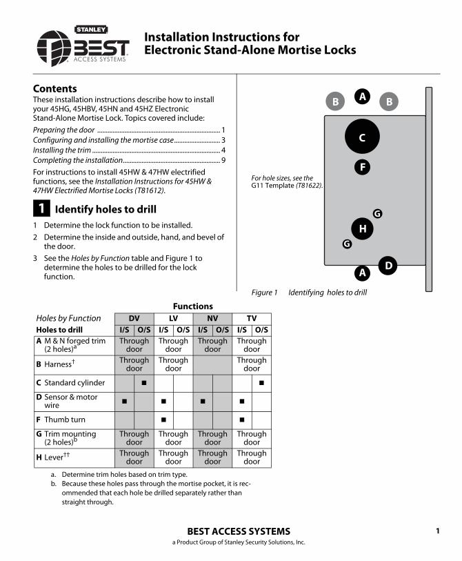
BEST ACCESS SYSTEMS a Product Group of Stanley Security Solutions, Inc. 1 Contents These installation instructions describe how to install your 45HG, 45HBV, 45HN and 45HZ Electronic Stand-Alone Mortise Lock. Topics covered include: Preparing the door ........................................................................ 1 Configuring and installing the mortise case........................... 3 Installing the trim ........................................................................... 4 Completing the installation......................................................... 9 For instructions to install 45HW & 47HW electrified functions, see the Installation Instructions for 45HW & 47HW Electrified Mortise Locks (T81612). 1 Identify holes to drill 1 Determine the lock function to be installed. 2 Determine the inside and outside, hand, and bevel of the door. 3 See the Holes by Function table and Figure 1 to determine the holes to be drilled for the lock function. B B A A C F H D G G Figure 1 Identifying holes to drill For hole sizes, see the G11 Template (T81622). Installation Instructions for Electronic Stand-Alone Mortise Locks Functions Holes by Function DV LV NV TV Holes to drill I/S O/S I/S O/S I/S O/S I/S O/S A M & N forged trim (2 holes) a a. Determine trim holes based on trim type. Through door Through door Through door Through door B Harness † Through door Through door Through door C Standard cylinder ■ ■ D Sensor & motor wire ■ ■ ■ ■ F Thumb turn ■ ■ G Trim mounting (2 holes) b b. Because these holes pass through the mortise pocket, it is rec- ommended that each hole be drilled separately rather than straight through. Through door Through door Through door Through door H Lever †† Through door Through door Through door Through door
Transcript of Installation Instructions for Electronic Stand-Alone ... · Installation Instructions for...
BEST ACCESS SYSTEMSa Product Group of Stanley Security Solutions, Inc.
1
ContentsThese installation instructions describe how to install your 45HG, 45HBV, 45HN and 45HZ Electronic Stand-Alone Mortise Lock. Topics covered include:Preparing the door ........................................................................ 1Configuring and installing the mortise case........................... 3Installing the trim ........................................................................... 4Completing the installation......................................................... 9For instructions to install 45HW & 47HW electrified functions, see the Installation Instructions for 45HW & 47HW Electrified Mortise Locks (T81612).
1 Identify holes to drill1 Determine the lock function to be installed.2 Determine the inside and outside, hand, and bevel of
the door.3 See the Holes by Function table and Figure 1 to
determine the holes to be drilled for the lock function.
B BA
A
C
F
H
D
G
G
Figure 1 Identifying holes to drill
For hole sizes, see the G11 Template (T81622).
Installation Instructions forElectronic Stand-Alone Mortise Locks
FunctionsHoles by Function DV LV NV TVHoles to drill I/S O/S I/S O/S I/S O/S I/S O/SA M & N forged trim
(2 holes)a
a. Determine trim holes based on trim type.
Through door
Through door
Through door
Through door
B Harness† Through door
Through door
Through door
C Standard cylinder ■ ■
D Sensor & motor wire ■ ■ ■ ■
F Thumb turn ■ ■
G Trim mounting (2 holes)b
b. Because these holes pass through the mortise pocket, it is rec-ommended that each hole be drilled separately rather than straight through.
Through door
Through door
Through door
Through door
H Lever†† Through door
Through door
Through door
Through door

Installation Instructions for Electronic Stand-Alone Mortise Locks
BEST ACCESS SYSTEMSa Product Group of Stanley Security Solutions, Inc.
Preparing the door
2
2 Align templates
Note: If the door is a fabricated hollow metal door, determine whether it is properly reinforced to support the lock. If door reinforcement is not adequate, consult the door manufacturer for information on proper reinforcement. For dimensions for preparing metal doors, see the G12 Template—Installation Specifications for 45HG/HBV, 45HN & 45HZ Mortise Locks (T81623).
1 Separate the four templates provided on the G11 Template—Installation Template for 45HG/HBV, 45HN & 45HZ Mortise Locks (T81622).
2 Position one of the door edge templates on the door, making sure that the lock case mortise shown on the template aligns with the mortise pocket prepared in the door.
3 Using the centerlines on the door edge template as a guide, position the appropriate door template on each side of the door. You need to take the bevel into account. Tape the templates to the door.
3 Center punch and drill holes
1 Center punch the necessary drill points. See the instructions on the template.
2 Drill the holes.Note 1: To locate the center of a hole on the opposite side of the door, drill a pilot hole completely through the door.Note 2: For holes through the door, it is best to drill half-way from each side of the door to prevent the door from splintering.
Figure 2 Aligning the templates
Installationtemplate
Door edgetemplate
CenterlineCenterline
Installation Instructions for Electronic Stand-Alone Mortise Locks
BEST ACCESS SYSTEMSa Product Group of Stanley Security Solutions, Inc.
3
Configuring & installing the mortise case
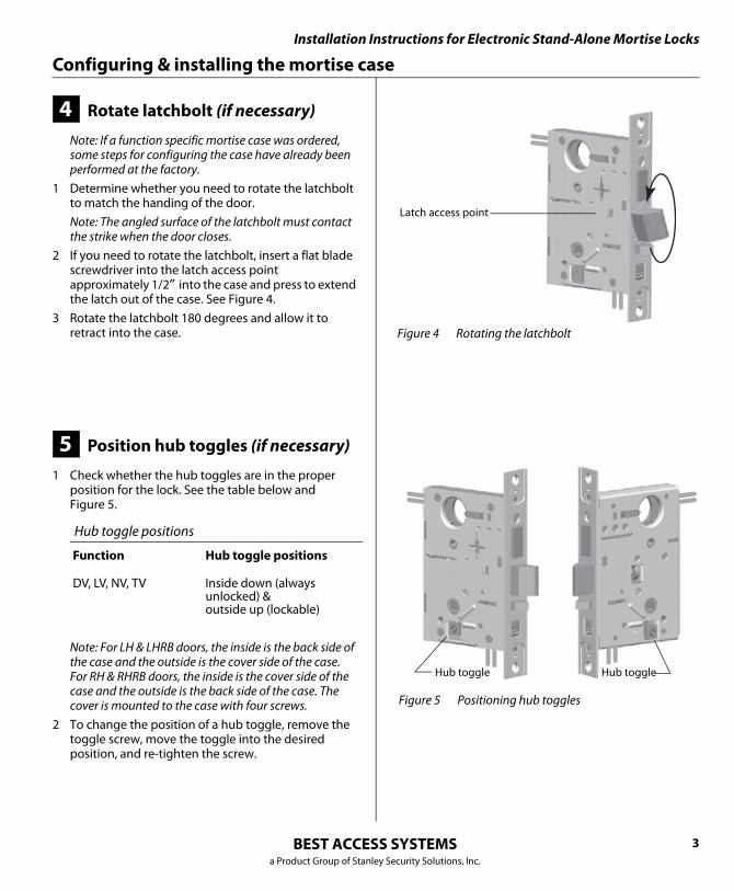
4 Rotate latchbolt (if necessary)
Note: If a function specific mortise case was ordered, some steps for configuring the case have already been performed at the factory.
1 Determine whether you need to rotate the latchbolt to match the handing of the door.Note: The angled surface of the latchbolt must contact the strike when the door closes.
2 If you need to rotate the latchbolt, insert a flat blade screwdriver into the latch access point approximately 1/2″ into the case and press to extend the latch out of the case. See Figure 4.
3 Rotate the latchbolt 180 degrees and allow it to retract into the case.
5 Position hub toggles (if necessary)
1 Check whether the hub toggles are in the proper position for the lock. See the table below andFigure 5.
Note: For LH & LHRB doors, the inside is the back side of the case and the outside is the cover side of the case. For RH & RHRB doors, the inside is the cover side of the case and the outside is the back side of the case. The cover is mounted to the case with four screws.
2 To change the position of a hub toggle, remove the toggle screw, move the toggle into the desired position, and re-tighten the screw.
Hub toggle positions
Function Hub toggle positions
DV, LV, NV, TV Inside down (always unlocked) &outside up (lockable)
Figure 4 Rotating the latchbolt
Latch access point
Figure 5 Positioning hub toggles
Hub toggleHub toggle

Installation Instructions for Electronic Stand-Alone Mortise Locks
BEST ACCESS SYSTEMSa Product Group of Stanley Security Solutions, Inc.
Installing the trim
4
6 Install mortise case
1 Drill the holes for the case mounting screws.2 Insert the mortise case into the mortise cavity, while
feeding the sensor and motor wires into the mortise cavity and out the sensor & motor wire hole to the inside of the door.Note: The armored front of the mortise case self-adjusts to the door bevel.
3 Secure the mortise case with the case mounting screws.
7 Install trim mounting plates
1 Insert the outside trim mounting plate through the door and mortise case.
2 Position the inside trim mounting plate opposite the outside trim mounting plate and screw them securely in place.Caution: Do not overtighten the trim mounting plate screws. Overtightening may damage the locking mechanism.
Figure 6 Installing the mortise case (inside of door)
Sensor & motor wire hole and wires
Mortise case
Mortise cavity
Casemounting screws
Remote unlock wires from switch (Keypad EZ only)
Figure 7 Installing the trim mounting plates
Outsidemountingplate
Insidemounting plate
Installation Instructions for Electronic Stand-Alone Mortise Locks
BEST ACCESS SYSTEMSa Product Group of Stanley Security Solutions, Inc.
5
Installing the trim
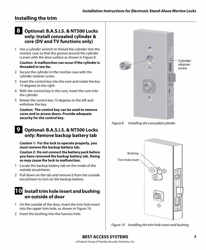
8 Optional: B.A.S.I.S. & NT500 Locks only: Install concealed cylinder & core (DV and TV functions only)
1 Use a cylinder wrench to thread the cylinder into the mortise case so that the groove around the cylinder is even with the door surface as shown in Figure 8.Caution: A malfunction can occur if the cylinder is threaded in too far.
2 Secure the cylinder in the mortise case with the cylinder retainer screw.
3 Insert the control key into the core and rotate the key 15 degrees to the right.
4 With the control key in the core, insert the core into the cylinder.
5 Rotate the control key 15 degrees to the left and withdraw the key.Caution: The control key can be used to remove cores and to access doors. Provide adequate security for the control key.
9 Optional: B.A.S.I.S. & NT500 Locks only: Remove backup battery tab
Caution 1: For the lock to operate properly, you must remove the backup battery tab.Caution 2: Do not connect the battery pack before you have removed the backup battery tab. Doing so may cause the lock to malfunction.
1 Locate the backup battery tab on the inside of the outside escutcheon.
2 Pull down on the tab and remove it from the outside escutcheon to turn on the backup battery.
10 Install trim hole insert and bushing on outside of door
1 On the outside of the door, insert the trim hole insert into the upper trim hole, as shown in Figure 10.
2 Insert the bushing into the harness hole.
Figure 8 Installing the concealed cylinder
Cylinderretainerscrew
Figure 10 Installing the trim hole insert and bushing
Trim hole insert
Bushing

Installation Instructions for Electronic Stand-Alone Mortise Locks
BEST ACCESS SYSTEMSa Product Group of Stanley Security Solutions, Inc.
Installing the trim
6
11 Route wire harnesses and position outside escutcheon
1 From the outside of the door, feed the motor connector, battery connector, and sensor connectors through the harness hole.Note: NV function locks do not have a sensor harness.Caution: When routing the connectors, make sure the harnesses are not routed across any sharp edges or over any surface that could damage their sleeving or wire insulation.
2 For DV and TV functions locks only, perform these steps:a Firmly press the outside escutcheon in position
on the door. The core should be flush with the outer surface of the escutcheon.
a If necessary, adjust the cylinder depth plus or minus one turn so that the core is flush with the outer surface of the escutcheon.
a Secure the cylinder in the mortise case with the cylinder clamp screw.
3 Rest the outside escutcheon on the door by inserting the trim studs into the trim holes.
12 Install fire plate1 From the inside of the door, feed the wiring through
the fire plate harness hole.2 Position the fire plate on the door so that the inside
mounting plate fits through the square opening in the fire plate.
3 Insert the two counter sunk mounting screws into the holes at the top and bottom of the fire plate.
4 Tighten the mounting screws until the fire plate is securely mounted to the door.
Figure 11 Feeding the wire harness connectors through the harness hole (B.A.S.I.S. & NT500 Lock shown)
Motorconnector
Outside escutcheon Outside of door
Sensorconnectors
Batteryconnector
Harnesshole
Figure 12 Installing the fire plate and bushing
Inside of door
Mounting screws
Installation Instructions for Electronic Stand-Alone Mortise Locks
BEST ACCESS SYSTEMSa Product Group of Stanley Security Solutions, Inc.
7
Installing the trim
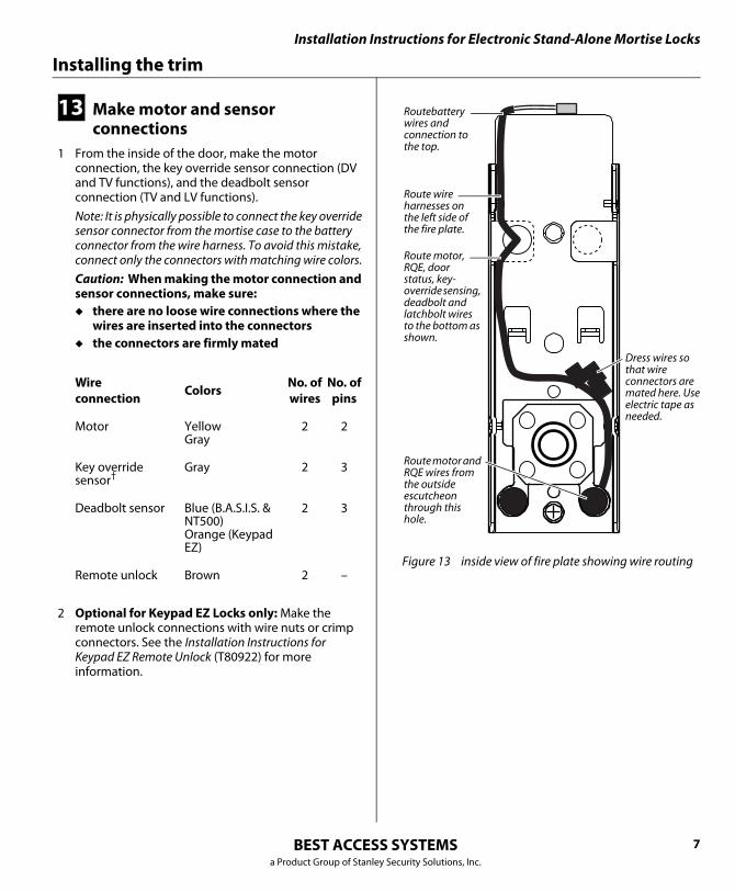
13 Make motor and sensor connections
1 From the inside of the door, make the motor connection, the key override sensor connection (DV and TV functions), and the deadbolt sensor connection (TV and LV functions).Note: It is physically possible to connect the key override sensor connector from the mortise case to the battery connector from the wire harness. To avoid this mistake, connect only the connectors with matching wire colors.Caution: When making the motor connection and sensor connections, make sure:◆ there are no loose wire connections where the
wires are inserted into the connectors◆ the connectors are firmly mated
2 Optional for Keypad EZ Locks only: Make the remote unlock connections with wire nuts or crimp connectors. See the Installation Instructions for Keypad EZ Remote Unlock (T80922) for more information.
Wire connection Colors No. of
wiresNo. ofpins
Motor YellowGray
2 2
Key override sensor†
Gray 2 3
Deadbolt sensor Blue (B.A.S.I.S. & NT500)Orange (Keypad EZ)
2 3
Remote unlock Brown 2 – Figure 13 inside view of fire plate showing wire routing
Routebattery wires and connection to the top.
Route wire harnesses on the left side of the fire plate.
Dress wires so that wire connectors are mated here. Use electric tape as needed.
Route motor, RQE, door status, key-override sensing, deadbolt and latchbolt wires to the bottom as shown.
Route motor and RQE wires from the outside escutcheon through this hole.

Installation Instructions for Electronic Stand-Alone Mortise Locks
BEST ACCESS SYSTEMSa Product Group of Stanley Security Solutions, Inc.
Installing the trim
8
14 Install bottom cover(inside escutcheon)
1 Position the battery wires above the side tabs and against the side of the fire plate, as shown inFigure 14.
2 Optional for Thumb Turn option only: Make sure that the Thumb Turn is in the upright position, as shown in Figure 14.
3 Use two cover screws to secure the cover to the side of the fire plate.Note: Phillips Type 2 and T20 Torx options are available for the cover mounting screws.Caution: Dress all wires away from possible pinch points before the bottom cover is put in place.
15 Optional: Keypad EZ Locks only: Install cylinder (DV and TV functions only)
1 Rotate the cylinder cam to the 12 o’clock position as shown in Figure 15.
2 Use a cylinder wrench to thread the cylinder into the mortise case. See Figure 15.
3 Secure the cylinder in the mortise case with the cylinder retainer screw.
4 Install the core.
Figure 14 Installing the bottom cover
Inside of door
Bottomcover
Coverscrews
Battery wires
Thumb turn(optional)
Side tabs
Battery holding tabs
1 2 3
4 5 6
7 8 9
* 0 #
Figure 15 Installing the Keypad EZ Lock cylinder
Outside of door
View of the back of the cylinder
Cam in 12 o’clock position
Cylinder
Cylinder retainer screw (inside mortise case)

Installation Instructions for Electronic Stand-Alone Mortise Locks
BEST ACCESS SYSTEMSa Product Group of Stanley Security Solutions, Inc.
9
Completing the installation
16 Install battery holder
1 Position the battery wires against the fire plate side wall, as shown in Figure 16.
2 Slide the battery holder behind the fire plate side tabs until it rests on the bent battery holding tabs.Caution: When routing the battery wires, make sure the wires are not routed across any sharp edges or over any surface that could damage their sleeving or wire insulation.
3 Connect the battery pack to the battery connector on the wire harness.Caution: When connecting the battery pack, make sure:
there are no loose wire connections where the wires are inserted into the connectors.the connectors are firmly mated.
17 Install inside and outside levers
1 Unscrew the inside spindle one full turn to allow the spindles to turn freely.
2 With the handle pointing toward the door hinges, insert the outside lever and spindles assembly into the lock from the outside of the door.
3 Slide the inside lever onto the inside spindle and secure it with the set screw.
4 Making sure that the core is positioned properly in the outside escutcheon (DV and TV function Locks only) and the escutcheons are aligned properly on the door, tighten the escutcheon mounting screws.Note for B.A.S.I.S. & NT500 Locks only: If a core is not available, you can use the cylinder wrench to help you align the core opening in the escutcheon.
5 Turn the levers to check that they operate smoothly.
Figure 16 Installing the battery holder
Inside of door
Battery holder
Battery wires
Battery wires
Figure 17 Installing the levers
Spindles
Locationof setscrew
Outside of door Inside of doorSpindlesOutside of door
Installation Instructions for Electronic Stand-Alone Mortise Locks
BEST ACCESS SYSTEMSa Product Group of Stanley Security Solutions, Inc.
Completing the installation
10
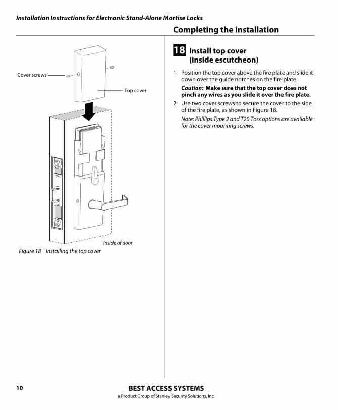
18 Install top cover(inside escutcheon)
1 Position the top cover above the fire plate and slide it down over the guide notches on the fire plate.Caution: Make sure that the top cover does not pinch any wires as you slide it over the fire plate.
2 Use two cover screws to secure the cover to the side of the fire plate, as shown in Figure 18.Note: Phillips Type 2 and T20 Torx options are available for the cover mounting screws.
Figure 18 Installing the top coverInside of door
Top cover
Cover screws

Installation Instructions for Electronic Stand-Alone Mortise Locks
BEST ACCESS SYSTEMSa Product Group of Stanley Security Solutions, Inc.
11
Completing the installation
19 Install mortise case faceplate
1 Secure the mortise case faceplate to the mortise case with the faceplate mounting screws.
2 Check the lock for proper operation.
20 Install strike box and strike plate
1 If the door jamb has not been mortised for the strike box and strike plate, perform these steps:a On the door jamb, locate the horizontal centerline
of the strike (3/8″ above the centerline of the lock), as well as the vertical centerline of the strike.
a Mortise the door jamb to fit the strike box and strike plate.
a Drill the holes for the screws used to install the strike box and strike plate.
2 If the strike box has a filled area, orient the strike box so that the filled area is down.
3 Insert the strike box into the mortise in the door jamb. Place the strike plate over the strike box and secure the strike with the screws provided.
4 Check the position of the auxiliary bolt against the strike plate (or the filled area of the strike box).Note: The recommended gap between the door and jamb is 1/8″
Figure 19 Installing the mortise case faceplate
Outside of door
Mortisecasefaceplate
Faceplatemounting screws
Figure 20 Installing the strike box and strike plate
Strikebox
Strikeplate
Filledarea
Strike box with filled area
Installation Instructions for Electronic Stand-Alone Mortise Locks
BEST ACCESS SYSTEMSa Product Group of Stanley Security Solutions, Inc.
12
Testing the lock
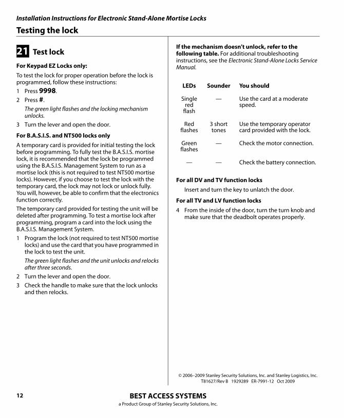
21 Test lock
For Keypad EZ Locks only:
To test the lock for proper operation before the lock is programmed, follow these instructions:1 Press 9998.2 Press #.
The green light flashes and the locking mechanism unlocks.
3 Turn the lever and open the door.
For B.A.S.I.S. and NT500 locks only
A temporary card is provided for initial testing the lock before programming. To fully test the B.A.S.I.S. mortise lock, it is recommended that the lock be programmed using the B.A.S.I.S. Management System to run as a mortise lock (this is not required to test NT500 mortise locks). However, if you choose to test the lock with the temporary card, the lock may not lock or unlock fully. You will, however, be able to confirm that the electronics function correctly. The temporary card provided for testing the unit will be deleted after programming. To test a mortise lock after programming, program a card into the lock using the B.A.S.I.S. Management System.1 Program the lock (not required to test NT500 mortise
locks) and use the card that you have programmed in the lock to test the unit.The green light flashes and the unit unlocks and relocks after three seconds.
2 Turn the lever and open the door.3 Check the handle to make sure that the lock unlocks
and then relocks.
If the mechanism doesn’t unlock, refer to the following table. For additional troubleshooting instructions, see the Electronic Stand-Alone Locks Service Manual.
For all DV and TV function locks
Insert and turn the key to unlatch the door.
For all TV and LV function locks
4 From the inside of the door, turn the turn knob and make sure that the deadbolt operates properly.
LEDs Sounder You should
Single red
flash
— Use the card at a moderate speed.
Red flashes
3 short tones
Use the temporary operator card provided with the lock.
Green flashes
— Check the motor connection.
— — Check the battery connection.
© 2006–2009 Stanley Security Solutions, Inc. and Stanley Logistics, Inc.T81627/Rev B 1929289 ER-7991-12 Oct 2009