Installation instructions EN Lubrication pump P623S for ... · Lubrication pump P623S for...
82
951-171-014-EN Version 01 2016/03/14 EN Lubrication pump P623S for single-line lubrication systems Installation instructions following machinery directive 2006/42/EC EN
Transcript of Installation instructions EN Lubrication pump P623S for ... · Lubrication pump P623S for...

951-171-014-EN
Version 01
2016/03/14
ENLubrication pump P623S for single-line lubrication systems
Installation instructions following machinery directive 2006/42/EC
EN

- 2 -951-171-014Version 01
EN
Jürgen Kreutzkämper Manager R&D GermanySKF Lubrication Business Unit
Stefan Schürmann Manager R&D Hockenheim/Walldorf SKF Lubrication Business Unit
EC Declaration of incorporation following machinery directive 2006/42/EC, annex II, part 1 BThe manufacturer, SKF Lubrication Systems Germany GmbH, Walldorf Facilities, Heinrich-Hertz-Str. 2-8, DE - 69190 Walldorf, hereby declares that the partly completed machinery
Designation: Electrically driven pump to supply lubricant during intermittent operation within a centralized lubrication systemType: P623SPart number: 645-xxxxx-x Year of construction: See type identification plate
complies with the following basic safety and health requirements of the EC machinery directive 2006/42/EC at the time when first being launched in the market.
1.1.2 · 1.1.3 · 1.3.2 · 1.3.4 · 1.5.1 · 1.5.6· 1.5.8 · 1.5.9 · 1.6.1 · 1.7.1 · 1.7.3 · 1.7.4
The special technical documents were prepared following Annex VII part B of this directive. Upon justifiable request, these special technical documents can be forwarded electronically to the respective national authorities. The person empowered to assemble the technical documentation on behalf of the manufacturer is the head of standardization. See manufacturer's address.
Furthermore, the following directives and standards were applied:2011/65/EU RoHS II 2014/30/EU Electromagnetic compatibility | Industry 2006/28/EC Electromagnetic compatibility | Automotive
Standard Edition Standard Edition Standard Edition Standard Edition
DIN EN ISO 12100 2011 DIN EN ISO 50581 2013 DIN EN 60034-1 2011 DIN EN 61000-6-4 2011
DIN EN ISO 809 2012 DIN EN 60947-5-1 2010 DIN EN 61000-6-2 2006
DIN EN 60204-1 2007 DIN EN 61131-2 2008 Amendment 2011
Amendment 2010 Amendment 2009
The partly completed machinery must not be put into service until the final machinery into which it is to be incorporated has been declared in conformity with the previsions of machinery directive 2006/42/EC and any other applicable directives.
Walldorf, February 24, 2016
EC Declaration of incorporation

- 3 - 951-171-014Version 01
ENLegal disclosure
Training coursesIn order to provide a maximum of safety and economic viability, SKF carries out de-tailed training courses. It is recommended that the training courses are attended. For more information please contact the re-spective SKF Service address.
Copyright© Copyright SKF.All rights reserved.
WarrantyThe instructions do not contain any informa-tion on the warranty. This can be found in our general terms and conditions.
DisclaimerThe manufacturer shall not be held respon-sible for damages caused by: ○ non appropriate use
faulty assembly, operation, setting, main-tenance, repair, negligence or accidents
○ use of inappropriate lubricants
○ improper or late response to malfunctions
○ unauthorized modifications of the product
○ the use of non-original SKF spare parts
Liability for loss or damage resulting from the use of our products is limited to the maximum purchase price. Liability for consequential damages of whatever kind is excluded.
Legal disclosureManufacturerSKF Lubrication Systems Germany GmbH
Manufacturer's facilitiesHead Office Walldorf Facilities Heinrich-Hertz-Str. 2-8 69190 Walldorf Germany Phone +49 (0) 6227 33-0 Fax: +49 (0) 6227 33-259
Berlin Facilities Motzener Straße 35/37 12277 Berlin Germany Phone +49 (0)30 72002-0 Fax +49 (0)30 72002-111 www.skf.com/lubrication
Hockenheim Facilities 2. Industriestraße 4 68766 Hockenheim Germany Phone +49 (0)62 05 27-0 Fax +49 (0)62 05 27-101
E-mail: [email protected]
www.skf.com/lubrication

- 4 -951-171-014Version 01
EN Table of contents
Table of contentsEC Declaration of incorporation following machinery directive 2006/42/EC ............................................................................................2Legal disclosure ......................................................................................................3Explanation of symbols, signs and abbreviations ...............................................7
1. Safety instructions .........................................................................91.1 General safety instructions ....................................................................91.2 General behaviour when handling the product ...................................91.3 Intended use ..........................................................................................101.4 Foreseeable misuse ..............................................................................101.5 Painting of plastic parts ........................................................................101.6 Notes related to the CE marking .........................................................111.7 Modifications of the product ................................................................111.8 Prohibition of certain activities ............................................................111.9 Inspections prior to delivery ................................................................111.10 Other applicable documents ................................................................111.11 Markings on the product ......................................................................121.12 Notes related to the type identification plate .....................................121.13 Persons authorized to operate the pump ..........................................131.13.1 Operator .................................................................................................131.13.2 Specialist in mechanics ........................................................................131.13.3 Specialist in electrics ............................................................................131.14 Briefing of external technicians...........................................................131.15 Provision of personal protective equipment ......................................131.16 Order ......................................................................................................131.17 Emergency stopping of the pump station ..........................................131.18 Transport, installation, maintenance, malfunctions, repair, shutdown, disposal. ..............................................................................141.19 Initial commissioning, daily start-up ..................................................151.20 Cleaning .................................................................................................151.21 Residual risks ........................................................................................16
2. Lubricants ................................................................................... 172.1 General information .............................................................................172.2 Selection of lubricants ..........................................................................172.3 Material compatibility ...........................................................................172.4 Temperature characteristics ................................................................172.5 Ageing of lubricants ..............................................................................18
3. Overview, functional description ................................................ 193.1 Functioning principle of the intermittent low-level indication .........243.2 Functioning principle of pressurization, holding time and pressure relief .......................................................................................253.3 Overview of the displays ......................................................................27
4. Technical data ............................................................................. 324.1 Mechanics ..............................................................................................324.2 Nominal output volumes .....................................................................334.2.1 Influencing variables on the actual output volume ...........................334.2.2 Output diagrams of typical NLGI 2 lubricants ....................................334.3 Useable reservoir volume ....................................................................344.4 Lubricant requirement for priming of an empty pump ....................344.5 Limits of use of the intermittent low-level indication .......................354.6 Factory settings .....................................................................................364.7 Tightening torques ...............................................................................374.8 Electrics: .................................................................................................384.8.1 Control pcb.............................................................................................394.8.2 Motor ......................................................................................................39

- 5 - 951-171-014Version 01
ENTable of contents
4.8.3 Relay circuit board ................................................................................394.8.4 Configuration of the control pcb ..........................................................404.9 Type identification code ........................................................................42
5. Delivery, returns, and storage .................................................... 435.1 Delivery ..................................................................................................435.2 Returns .................................................................................................435.3 Storage ...................................................................................................435.4 Storage temperature range .................................................................435.5 Special storage conditions for parts primed with lubricant .............445.5.1 Storage period of up to 6 months .......................................................445.5.2 Storage period from 6 to 18 months ..................................................445.5.3 Storage period exceeding 18 months ................................................44
6. Assembly ..................................................................................... 456.1 General information .............................................................................456.2 Place of installation ...............................................................................456.3 Mechanical connection .........................................................................466.3.1 Minimum assembly dimensions .........................................................466.3.2 Installation bores ..................................................................................476.4 Electrical connection ............................................................................486.5 Lubrication line connection .................................................................496.6 Programming ........................................................................................506.6.1 Legend of the programming scheme .................................................506.6.2 Filling via filler fitting .............................................................................526.6.3 Filling via the reservoir lid in case of pumps without follower plate 53
7. Initial start-up ............................................................................ 547.1 Inspections prior to initial start-up .....................................................547.2 Inspections during initial start-up ......................................................54
8. Order ........................................................................................... 558.1 Refill lubricant .......................................................................................558.2 Query mode ...........................................................................................568.2.1 Flow chart of query mode in case of time control .............................568.2.2 Flow chart of query mode in case of pulse control............................57
9. Cleaning ...................................................................................... 589.1 Cleaning agents .....................................................................................589.2 Exterior cleaning ...................................................................................589.3 Interior cleaning ....................................................................................58
10. Maintenance ............................................................................... 59
11. Troubleshooting .......................................................................... 60
12. Repairs ........................................................................................ 6212.1 Check pump element and replace pressure control valve. ...............6212.2 Replace membrane keypad .................................................................6312.3 Replace control printed circuit board ..................................................6512.4 Replace relay circuit board ...................................................................6612.5 Replace power supply board ................................................................67

- 6 -951-171-014Version 01
EN Table of contents
12.6 Tests after replacement of the power supply board ..........................6912.6.1 Visual check ...........................................................................................6912.6.2 Electrical safety test ..............................................................................6912.6.3 Electrical functionality test ...................................................................69
13. Shutdown and disposal ............................................................... 7013.1 Temporary shutdown ...........................................................................7013.2 Final shutdown and disassembly ........................................................7013.3 Disposal ..................................................................................................70
14. Spare parts ................................................................................. 7114.1 Housing front cover, assy. ....................................................................7114.2 Pump element Z7 .................................................................................7114.3 Pressure control valve ..........................................................................7114.4 Control pcb.............................................................................................7214.5 Relay circuit board ................................................................................7214.6 Power supply board ..............................................................................72
15. Electrical connections ................................................................. 7315.1 Cable colours following IEC60757 ......................................................7315.2 Wire allocation of the connectors ........................................................7315.3 Assignment of the circuit diagrams to the pump type identification code .............................................................7315.4 Connection diagram P623S-PCB-M-DS-DT-SN-H1 ...................7415.5 Connection diagram P623S-PCB-M-DS-DT-SN-H1-H2-LLC ....7515.6 Connection diagram P623S-PCB-M-DS-DT-H1-H1-LLC-RPCB 7615.7 Connection diagram P623S-PCB-M-DS-DT-SN-H1-H2-LF .......7715.8 Connection diagram P623S-PCB-M-DS-DT-H1-H1-LF-RPCB ..7815.9 Functional flow chart P623S with internal pressure sensor/ pressure switch ........................................7915.10 Functional flow chart P623S with internal and external pressure sensor/ pressure switch .................80

- 7 - 951-171-014Version 01
ENExplanation of symbols, signs and abbreviations
Explanation of symbols, signs and abbreviations
General warning Dangerous electrical voltage Risk of falling Hot surfaces
Unintentional intake Crushing hazard Pressure injection Suspended load
Electrostatically sensitive components
Wear personal protective equipment (goggles)
Wear personal protective equipment (face shield)
Wear personal protective equipment (gloves)
Wear personal protective equipment (protective clothes)
Wear personal protective equipment (safety shoes)
Release the product. General obligation
Keep unauthorized persons away.
Protective earthSafety extra-low voltage (SELV)
Safe galvanic isolation (SELV)
CE marking Disposal, recyclingDisposal of waste electrical and electronic equipment
Warning level Consequence Probability Symbol Meaning
DANGERDeath, serious injury
imminent Chronological guidelines
WARNING Serious injury possible Lists
CAUTIONMinor injury
possible Refers to other facts, causes, or consequences
NOTICE Property damage possible
The following abbreviations may be used within these instructions. Symbols within safety notes mark the kind and source of the hazard.

- 8 -951-171-014Version 01
EN Explanation of symbols, signs and abbreviations
Abbreviations and conversion factors
re. regarding °C degrees Celsius °F degrees Fahrenheitapprox. approximately K Kelvin Oz. Ouncei.e. that is N Newton fl. oz. fluid ounceetc. et cetera h hour in. inchposs. possibly s second psi pounds per square inchif appl. if applicable d day sq.in. square incha.a.r. as a rule Nm Newtonmeter cu. in. cubic inchincl. including ml millilitre mph miles per hourmin. minimum ml/d millilitre per day rpm revolutions per minutemax. maximum cc cubic centimetre gal. gallonmin. minute mm millimetre lb. poundetc. et cetera l litre hp horse powere.g. for example dB (A) Sound pressure level kp kilopoundkW kilowatt > greater than fpsec feet per secondU Voltage < less than Conversion factorsR resistance ± plus/minus Length 1 mm = 0.03937 in.I current Ø diametre Area 1 cm² = 0.155 sq.inV volt kg kilogram Volume 1 ml = 0.0352 fl.oz.W watt rh relative humidity 1 l = 2.11416 pints (US)AC alternating current ≈ about Mass 1 kg = 2.205 lbsDC direct current = equal to 1 g = 0.03527 oz.A ampere % per cent Density 1 kg/cc = 8.3454 lb./gal(US)Ah Ampere hour ‰ per mille 1 kg/cc = 0.03613 lb./cu.in.Hz Frequency [Hertz] ≥ greater than Force 1 N = 0.10197 kpnc normally closed ≤ less than Pressure 1 bar = 14.5 psino normally open contact mm2 square millimetre Temperature °C = (°F-32) x 5/9OR logical OR rpm-1 revolutions per minute Output 1 kW = 1.34109 hp& logical AND Acceleration 1 m/s² = 3.28084 ft./s²
Speed 1 m/s = 3.28084 fpsec.1 m/s = 2.23694 mph

1
- 9 - 951-171-014Version 01
EN1. Safety instructions
1. Safety instructions
1.1 General safety instructions
○ The owner must ensure that safety infor-mation has been read by any persons en-trusted with works on the product or by those persons who supervise or instruct the before-mentioned group of persons. In addition, the owner must also ensure that the relevant personnel are fully fa-miliar with and have understood the con-tents of the Instructions. It is prohibited to commission or operate the product prior to reading the Instructions.
○ These Instructions must be kept for fur-ther use.
○ The described products were manufac-tured according to the state of the art. Risks may, however, arise from a usage not according to the intended purpose and may result in harm to persons or damage to material assets.
○ Any malfunctions which may affect safety must be remedied immediately. In addi-tion to these Instructions, general statu-tory regulations for accident prevention and environmental protection must be observed.
1.2 General behaviour when handling the product
○ The product may be used only in aware-ness of the potential dangers, in proper technical condition, and according to the information in these instructions.
○ Familiarize yourself with the functions and operation of the product. The speci-fied assembly and operating steps and their sequences must be observed.
○ Any unclear points regarding proper condition or correct assembly/ operation must be clarified. Operation is prohibited until issues have been clarified.
○ Unauthorized persons must be kept away.
○ Precautionary operational measures and instructions for the respective work must be observed.
○ Responsibilities for different activities must be clearly defined and observed. Uncertainty seriously endangers safety.
○ Safety-related protective and emergency devices must not be removed, modified or affected otherwise in their function and are to be checked at regular intervals for completeness and function.
○ If protective and safety equipment has to be dismantled, it must be reassembled immediately after finishing the work, and then checked for correct function.
○ Remedy occurring faults in the frame of responsibilities. Immediately inform your superior in the case of faults beyond your competence.
○ Wear personal protective equipment.
○ Never use parts of the centralized lu-brication system or of the machine as standing or climbing aids.

- 10 -951-171-014Version 01
EN 1. Safety instructions
1.3 Intended use
Supply of lubricants within a single-line system following the specifications, technical data and limits stated in these Instructions:Usage is allowed exclusively for professional users in the frame of commercial and eco-nomic activities.
1.4 Foreseeable misuse
Any usage differing from the one stated in these Instructions is strictly prohibited. It is expressly forbidden to be used: ○ outside the indicated operating tempera-
ture range
○ with non-specified means of operation
○ without adequate pressure relief valve
○ in continuous operation
○ in areas with aggressive or corrosive ma-terials (e.g. high ozone pollution). These may affect seals and painting.
○ in areas with harmful radiation (e. g. ion-ising radiation)
○ to supply, transport, or store hazardous substances and mixtures in accordance with annex I part 2-5 of the CLP regula-tion (EG 1272/2008) and marked with GHS01 - GHS06 and GHS08 hazard pictograms.
○ to feed, forward, or store gases, liquefied gases, dissolved gases, vapours, or fluids whose vapour pressure exceeds normal atmospheric pressure (1013 mbar) by more than 0.5 bar at the maximum per-missible operating temperature.
○ in an explosion protection zone.
1.5 Painting of plastic parts
Painting of any plastic parts or seals of the described products is expressly prohibited. Remove or tape plastic parts completely before painting the superior machine

1
- 11 - 951-171-014Version 01
EN1. Safety instructions
1.6 Notes related to the CE marking
CE marking is effected following the re-quirements of the applied directives: ○ 2014/30/EU
Electromagnetic compatibility
○ 2011/65/EU (RoHS II) Directive on the restriction of the use of certain hazardous substances in electrical and electronic equipment
Reference on Low Voltage Directive 2014/35/EUThe protective regulations of Low Voltage Directive 2014/35/EU are fulfilled accord-ing to annex I (1.5.1) of Machinery Directive 2006/42/EC.Reference on Pressure Equipment Directive 2014/68/EU Because of its performance data the prod-uct does not achieve the limit values defined in Article 4 (1) (a) (i) and is therefore exclud-ed from the scope of application of Pressure Equipment Directive 2014/68/EU following Article 4 (3).
1.7 Modiications of the productUnauthorized conversions or modifica-tions may result in unforeseeable impacts on safety. Therefore, any unauthorized conversions or modifications are expressly prohibited.
1.8 Prohibition of certain activities
Due to potential sources of faults that may not be visible the following activities may be carried out by trained and authorized specialists only: ○ Repairs or changes to the electrical
equipment of the pump
○ Replacement of or changes on the pis-tons of the pump elements
1.9 Inspections prior to delivery
The following inspections were carried out prior to delivery: ○ Safety and functional tests
○ Electrical inspections following DIN EN 60204-1:2007 / VDE 0113-1:2007 (for electrically driven products.
1.10 Other applicable documents
In addition to these instructions, the fol-lowing documents must be observed by the respective target group: ○ Operational instructions and approval
rules
○ Safety data sheet of the lubricant used
Where appropriate: ○ Project planning documents
○ Additional information on special ver-sions of the pump. You will find these in the special system documentation.
○ Any documents of other components required to set up the centralized lubrica-tion system

- 12 -951-171-014Version 01
EN 1. Safety instructions
1.11 Markings on the product
Warning of dangerous electrical voltage
Warning of spring-loaded com-ponents when opening the res-ervoir lid of pumps with follower plate
Warning of unintended intake by the stirring paddle with the res-ervoir lid being open
Marks the protective conductor connection
1.12 Notes related to the type identiica-tion plate
The type identification plate states im-portant characteristics such as type des-ignation, order number, and regulatory characteristics.To ensure that the loss of data due to an illegible type identification plate is avoided, the characteristics should be entered in the Instructions.
Model: ________________________________
P. No. _________________________________
S. No. _________________________________
(CW/YY) _______________________________ Calendar week/year of construction
SKF Lubrication Systems Germany GmbH
Model:P. No.:S. No.:
P623S645-xxxxx-xxxxxxxxxxxxx
Made in Germany D-69190 Walldorf
pmax:U:P:
xxx bar / xxxx psi110-240 VAC / 50 - 60 Hz Phase 160 VA
S. No.: xxxxxxxxxxx
KW/JJ
1
- 13 - 951-171-014Version 01
EN1. Safety instructions
1.13 Persons authorized to operate the pump
1.13.1 Operator
A person who is qualified by training, know-ledge and experience to carry out the func-tions and activities related to normal opera-tion. This includes avoiding possible hazards that may arise during operation.
1.13.2 Specialist in mechanics
Person with appropriate professional edu-cation, knowledge and experience to detect and avoid the hazards that may arise during transport, installation, start-up, operation, maintenance, repair and disassembly.
1.13.3 Specialist in electrics
Person with appropriate professional edu-cation, knowledge and experience to detect and avoid the hazards that may arise from electricity.
1.14 Brieing of external techniciansPrior to commencing the activities, external technicians must be informed by the opera-tor of the company safety provisions, the applicable accident prevention regulations to be maintained, and the functions of the superordinate machine and its protective devices.
1.15 Provision of personal protective equipment
The operator must provide suitable per-sonal protective equipment for the respec-tive location of operation and the purpose of operation.
1.16 Order
The following must be observed during commissioning and operation. ○ Any information within this manual and
the information within the referenced documents.
○ All laws and regulations to be complied with by the user.
1.17 Emergency stopping of the pump station
In case of an emergency stop the pump sta-
tion by: ○ Interrupting the power supply to the
pump
○ Using measures determined by the op-erator, such as actuating the emergency stop switch of the superior machine.

- 14 -951-171-014Version 01
EN 1. Safety instructions
○ Carry out electrical connections only ac-cording to the information in the valid wiring diagram and taking the relevant regulations and the local connection con-ditions into account.
○ Do not touch cables or electrical compo-nents with wet or damp hands.
○ Fuses must not be bypassed. Replace defective fuses always by fuses of the same type.
○ To avoid potential differences, where ap-plicable, use the potential connection of the pump.
○ Adhere to any protective measures, e. g. connection of protective conductor, IP type of protection, safety distances.
○ Undertake drilling at non-critical, non-load bearing parts only. Use any available boreholes. Do not damage lines and ca-bles when drilling.
○ Observe possible abrasion points. Protect the parts accordingly.
○ Ensure through suitable measures that movable or detached parts are immobi-lized during the work and that no limbs can be caught in between by inadvertent movements.
○ Assemble the product only outside of the operating range of moving parts, at an adequate distance from sources of heat or cold. Other units of the machine or ve-hicle must not be damaged or impaired in their function by the installation.
○ Dry or cover wet, slippery surfaces accordingly.
○ Cover hot or cold surfaces accordingly.
○ Work on electrical components must be carried out by electrical specialists only. Observe any waiting periods for dis-charging, if necessary. Carry out works on electrical components only while the system is depressurized and use voltage isolated tools suitable for electrical works only.
1.18 Transport, installation, maintenance, malfunctions, repair, shutdown, disposal.
○ All relevant persons must be informed of the activity prior to starting any work. Observe the precautionary measures and work instructions provided by the operator.
○ Carry out transport using suitable trans-port and hoisting equipment on suitable ways only.
○ Maintenance and repair work can be subject to restrictions in low or high tem-peratures (e.g. changed flow properties of the lubricant). Therefore, where possible, try to carry out maintenance and repair work at room temperature.
○ Prior to performing work, the product and the machine, into which the product will be integrated, must be depressurized and secured against unauthorized activa-tion. Observe all electrotechnical safety regulations.

1
- 15 - 951-171-014Version 01
EN1. Safety instructions
1.19 Initial commissioning, daily start-up
Ensure that: ○ All safety devices are completely available
and functional
○ All connections are correctly connected
○ All parts are correctly installed
○ All warning labels on the product are present completely, highly visible and undamaged
○ Illegible or missing warning labels are to be replaced without delay
○ All components used must be designed according to the maximum operating pressure and the maximum respectively minimum operating temperature.
○ No parts of the centralized lubrication system may be subjected to torsion, shear, or bending.
○ Check all parts prior to their usage for contamination and clean, if necessary.
○ Lubricant lines should be primed with lubricant prior to installation. This makes the subsequent ventilation of the system easier.
○ Observe the specified tightening torques. When tightening, use a calibrated torque wrench.
○ When working with heavy parts use suit-able lifting tools.
○ Avoid mixing up or wrong assembly of dismantled parts. Mark these parts accordingly.
1.20 Cleaning
○ Risk of fire and explosion when using inflammable cleaning agents. Only use non-flammable cleaning agents suitable for the purpose.
○ Do not use aggressive cleaning agents.
○ Thoroughly remove residues of cleaning agents from the product.
○ Do not use steam jet and high pressure cleaners. Components may be damaged. Observe the IP type of protection of the pump.
○ Cleaning work may not be carried out on energized components.
○ Mark damp areas accordingly.

- 16 -951-171-014Version 01
EN 1. Safety instructions
1.21 Residual risks
Residual risk Possible in life cycle Prevention/ remedy
Personal injury/ material damage due to falling of raised parts
A B C G H KKeep unauthorized persons away. No people may remain under suspended loads. Lift parts with adequate lifting devices.
Personal injury or material damage due to tilting or falling of the product because of non-observance of the stated tighten-ing torques
B C GObserve the specified tightening torques. Fix the product only to components with sufficient load capacity. If no tightening torques are stated, apply tightening torques according to the screw size characteristics for 8.8 screws.
Personal injury/ material damage due to electric shock in case of damage to the connection cable
B C D E F G HCheck the connection cable with regard to damages before the first usage and then at regular intervals. Do not mount cable to moving parts or friction points. If this cannot be avoided, use spring coils respectively protective conduits.
Personal injury/ damage to material due to spilled or leaked lubricant
B C D F G H K
Be careful when filling the reservoir and when connecting or disconnecting lubricant feed lines. Always use suitable hydraulic screw connections and lubri-cation lines for the stated pressures. Do not mount lubrication lines to moving parts or friction points. If this cannot be avoided, use spring coils respectively protective conduits.
Life cycles: A = transport, B = installation, C = initial start-up, D = operation, E = cleaning, F = maintenance, G = fault, repair, H = shutdown K = Disposal

2
- 17 - 951-171-014Version 01
EN2.Lubricants
2. Lubricants
2.1 General information
Lubricants are used specifically for cer-tain application purposes. In order to fulfil their tasks, lubricants must fulfil various requirements. The most important requirements for lubri-cants are: ○ Reduction of abrasion and wear
○ Corrosion protection
○ Noise minimisation
○ protection against contamination or penetration of foreign objects
○ Cooling (primarily with oils)
○ longevity (physical/ chemical stability)
○ economic and ecological aspects
2.2 Selection of lubricants
SKF considers lubricants to be an element of system design. A suitable lubricant is se-lected already when designing the machine and forms the basis for the planning of a centralized lubrication system.The selection is made by the manufacturer or operator of the machine, preferably to-gether with the lubricant supplier based on the requirement profile defined.Should you have little or no experience with the selection of lubricants for centralized lubrication systems, please contact SKF.If required we will be glad to support cus-tomers to select suitable components for feeding the selected lubricant and to plan and design their centralized lubrication system.You will avoid possible downtimes through damage to your machine or system or damage to the centralized lubrication system.
2.3 Material compatibility
Lubricants must generally be compatible with the following materials: ○ steel, grey iron, brass, copper, aluminium
○ NBR, FPM, ABS, PA, PU
2.4 Temperature characteristics
The lubricant used must be suitable for the specific operating temperature of the pump. The viscosity and consistency range required for proper operation of the prod-uct must be adhered to and must not be exceeded in case of low temperatures nor fall below specification in case of high tem-peratures. Specified viscosities, see chapter Technical data.

- 18 -951-171-014Version 01
EN 2. Lubricants
Only lubricants specified for the product may be used. Unsuitable lubricants may lead to a failure of the product.
Do not mix lubricants. This may have unforeseeable effects on the usability and therefore on the function of the centralized lubrication system.
When handling lubricants the relevant safety data sheets and hazard designations, if any, on the packaging have to be observed.
2.5 Ageing of lubricants
After a prolonged downtime of the machine, the lubricant must be inspected prior to re-commissioning as to whether it is still suitable for use due to chemical or physical ageing. We recommend that you undertake this inspection already after a machine downtime of 1 week. If doubts arise as to a further suitability of the lubricant, please replace it prior to re-commissioning and, if necessary, undertake initial lubrication manually.It is possible for lubricants to be tested in the company's laboratory for their suitability for being pumped in centralized lubrication systems (e.g. "bleeding").Please contact SKF. if you have further questions regarding lubricants.
Due to the multitude of possible additives, individual lubricants, which according to the manu-facturer's data sheets fulfil the necessary specification, may not, in fact, be suitable for use in centralized lubrication systems (e.g. incompatibility between synthetic lubricants and materi-als). In order to avoid this, always use lubricants tested by SKF.

3
- 19 - 951-171-014Version 01
EN3. Overview, functional description
3. Overview, functional description
1 reservoirThe lubricant is stored in the reservoir. De-pending on the pump version there are differ-ent types of reservoirs and reservoir sizes.
1.1 Reservoir venting deviceIt provides air for the reservoir while the pump is operating and supplying lubricant. It vents the reservoir while the pump is filled via the filler fitting.
2. Pump housingAll electrical components are accommodated in the pump housing. Exception: In case of the version with follower plate the switching rod for the low-level indication is positioned in the reservoir.
3. Housing front coverOn the housing front cover there is the mem-brane keypad to operate and adjust the pump. Furthermore, if service is required, the housing front cover provides access to the inside elec-trical components.
Overview Fig. 1
1
1.1
2
3
- 20 -951-171-014Version 01
EN 3. Overview, functional description
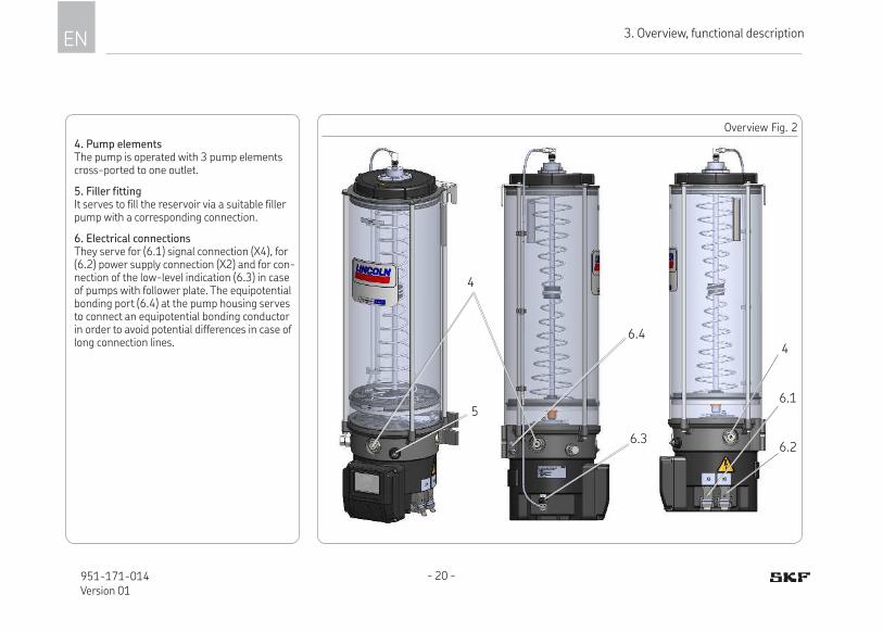
4. Pump elementsThe pump is operated with 3 pump elements cross-ported to one outlet.
5. Filler fittingIt serves to fill the reservoir via a suitable filler pump with a corresponding connection.
6. Electrical connectionsThey serve for (6.1) signal connection (X4), for (6.2) power supply connection (X2) and for con-nection of the low-level indication (6.3) in case of pumps with follower plate. The equipotential bonding port (6.4) at the pump housing serves to connect an equipotential bonding conductor in order to avoid potential differences in case of long connection lines.
Overview Fig. 2
4
5
6.2
6.1
6.3
6.4
4

3
- 21 - 951-171-014Version 01
EN3. Overview, functional description
7. ProProtect indicationIf the LED (7) is green, the ProProtect protec-tion up to 8 kV is available.
If the LED (7) is off despite existing operating voltage, only the standard protection level (EN 61000-6-4) is available. However, the pump is still fully functional.
Overview Fig. 3
7

- 22 -951-171-014Version 01
EN 3. Overview, functional description
Overview Fig. 4
10
8
8. 2 Follower plate (in case of pumps with fol-lower plate)The follower plate (8) rests on the lubricant and presses it down in the direction of the pump ele-ments by spring force. As a result the suction behaviour of the pump improves.
9. Contact rodThe contact rod (9) of the follower plate accom-modates the reed contacts for the low-level func-tion. In the follower plate there is a magnet that actuates the reed contact when reaching a certain switch point. The reed contact for the low-level indication is positioned at the lower switch point.
10 Stirring paddle (in case of pumps with stir-ring paddle)While the pump operates, the stirring paddle homogenises and smoothens the lubricant. The stirring paddle's lower vertical part pushes the lu-bricant towards the pump elements thus improv-ing the suction behaviour of the pump.
9

3
- 23 - 951-171-014Version 01
EN3. Overview, functional description
17 Membrane keypadThe membrane keypad (17) with display is the primary operating and display element of the pump. It offers the following functions:
18 DisplayDisplay of operating states, error codes and programming parameters
19 Set buttonConfirming faults in the operating mode Retrieve programming steps in the program-ming mode
20 Shift keyTrigger an additional lubrication in the operat-ing mode
Display and change parameters in the query and programming mode
Pump adjustments are made via the green adjustment key (19) and the red switch key (20) and are shown on the display (18).
All functions, except from the display of error codes, are available during the pump's pause time only.
Overview Fig. 5
18
2019
On
min h
17
On
min h
On
min h
17

- 24 -951-171-014Version 01
EN 3. Overview, functional description
3.1 Functioning principle of the intermittent low-level indication
The intermittent low-level indication operates free of contact. Its main components are the following: ○ firmly positioned magnetic switch (I) inside of the reservoir bottom ○ flexible guide plate (II) connected to the stirring paddle with a magnet (III) and a control cam (IV)
If the reservoir is filled with a lubrication grease suitable for the intermittent low-level indication and the pump is operating, then the guide plate (II) is de-flected by the resistance of the lubrication grease. As a consequence the magnet (III) connected to the guide plate (II) is moved on its inner circuit and does not trigger a pulse of the magnetic switch (I) with its magnetic field. A control cam (IV) positively guides the round magnet together with the pivoted guide plate towards the outside during each revolution. As soon as the guide plate leaves the control cam, the lubricant's resistance pushes the guide plate to-gether with the magnet to the inside again. As soon as the lubricant inside the reservoir has fallen to that level that the lubricant's resistance is no more sufficient to further deflect the guide plate (II), the magnet (III) remains on the outer circuit and triggers a pulse each time it slides across the magnetic switch (I). If during an operating cycle the magnet (III) slides across the magnetic switch (I) six times, a low-level signal is sent by the control printed circuit board of the pump. For programming of the external control of the pump, see corresponding chapter in these instructions.
Perspective representation Schematic representation
Magnet on inner circuit Magnet on outer circuit
I II
III
I
IIII
IV

3
- 25 - 951-171-014Version 01
EN3. Overview, functional description
3.2 Functioning principle of pressuri-zation, holding time and pressure relief
Functional chart, see the following page
The following procedure must be completed within the fixed monitor-ing time of 30 minutes. Otherwise a failure will be indicated.
Phase 1 Pressurization: When the pause time (PT) has lapsed, the pump starts pressurization within the pressurization time A1. At the same time the monitoring time starts to lapse.
Phase 2 Holding time: When the operating pressure set on the pressure switches/ sensors is reached, the pump motor will be switched off and the pressure holding time (PHT) consisting of several fixed holding times will start to lapse.
As long as the pressure holding time (PHT) lapses, pressure on the pressure switches/ sen-sors will be monitored. The pump motor may be switched on shortly to avoid inadmissibly high pressure fluctuations.
Reaching and holding the operating pressure via the pressure holding time (PHT) ensures that the single-line metering devices provide the lube points with lubricating grease properly.
Phase 3 Pressure relief: When the pressure holding time (PHT) has lapsed, the main line will be relieved from pres-sure. The relief process is monitored at the switch-back points.
Phase 4 Pause time (PT) The pump is in the preset pause time.

- 26 -951-171-014Version 01
EN 3. Overview, functional description
Functional diagram P623S Fig. 6
//
P1
P2
P1R
P2R
A1 H1 H2 H3 PT
PHT
Z
P
T
�
�
�
�
L1
L2
Legend
L1 Internal pressure course
L2 External pressure course
P1 Operating pressure in case of in-ternal pressure switches/ sensors
P2 Operating pressure in case of ex-ternal pressure switches/ sensors
P1R Switch-back pressure in case of internal pressure switches/ sensors
P2R Switch-back pressure in case of ex-ternal pressure switches/ sensors
PHT Pressure holding time
H1 - H3 Holding timesA1 Pressure build-up timePT Pause timeZ Lubrication interval
� Switch point of internal oper-ating pressure P1
� Switch-back point of internal operating pressure P1R
� Switch point of external op-erating pressure P2
� Switch-back point of external operating pressure P2R

3
- 27 - 951-171-014Version 01
EN3. Overview, functional description
3.3 Overview of the displays
Starting process Fault signals
Functional test after switching on.All segments are lit for about 2 seconds.
Fault signal EPA fault of the membrane keypad or the display is pending.
Pressure control via internal pressure switch
Fault signal E1 (flashing)Fault of pressurization (internal pressure control). Pressure P1 was not reached within the monitoring time.
Pressure control via internal and external pres-sure switches
Fault signal E2 (flashing)Fault of pressurization (internal or external pressure control). Pressure P1 or P2 was not reached within the monitoring time.
Pressure control via internal pressure sensor
Fault signal E3 (flashing)Fault of pressure relief (internal pressure control). Pressure P1R was not undercut within the monitor-ing time.
Pressure control via internal and external pres-sure sensors
Fault signal E4 (flashing)Fault of pressure relief (external pressure control). Pressure P2R was not undercut within the monitor-ing time.

- 28 -951-171-014Version 01
EN 3. Overview, functional description
Order
Operating voltageThe operating voltage of the pump is switched on
Pause timeAfter the pressure relief the pause time („br“ = break) starts
Operating voltage and machine contactThe operating voltage and the machine contact are switched on.
Holding time H1For internal pressure sensorsAfter building up the operating pressure, the holding time starts to lapse
Pump is on (operating time)The rotational direction of the motor is clockwise (forward).
Holding time H2For internal and external pressure sensors/ pressure switchesThe operating pressure of at least one pressure sensor or pres-sure switch was not reached within holding time H1
Pump is on (pressure relief)The rotational direction of the motor is anticlock-wise (backward) shortly for pressure relief
Holding time H3For internal and external pressure sensors/ pressure switchesThe operating pressure of at least one pressure sensor or pres-sure switch was not reached within holding time H2
Low-level signal (flashing)The ongoing lubrication cycle will still be com-pleted. An automatic restart will take place after filling only. An additional lubrication, however, can be initiated by hand on the pump or in case of an existing machine contact via the control stand.
Change of rotational direction It is indicated shortly after the holding time and signalises that the pump will change the rotational direction shortly for pres-sure relief purposes
3
- 29 - 951-171-014Version 01
EN3. Overview, functional description
Programming mode
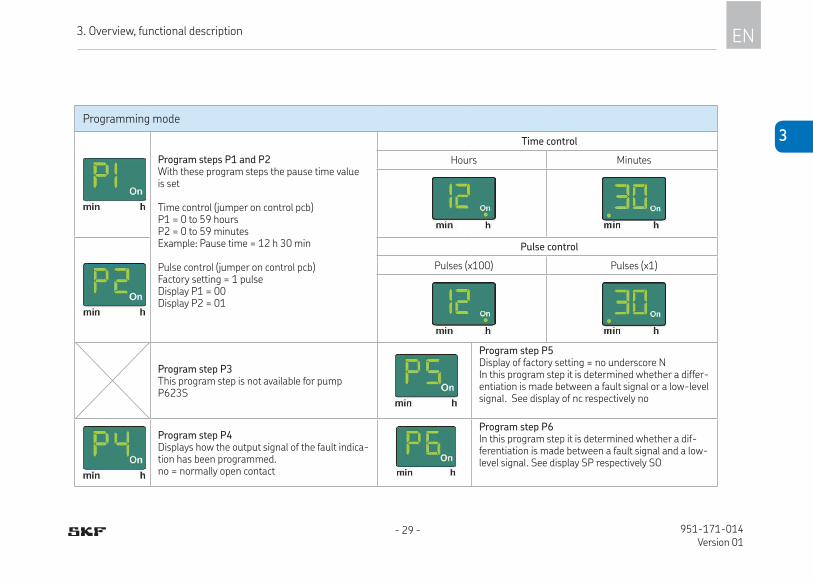
Program steps P1 and P2 With these program steps the pause time value is set
Time control (jumper on control pcb)P1 = 0 to 59 hours P2 = 0 to 59 minutesExample: Pause time = 12 h 30 min
Pulse control (jumper on control pcb)Factory setting = 1 pulse Display P1 = 00 Display P2 = 01
Time control
Hours Minutes
Pulse control
Pulses (x100) Pulses (x1)
Program step P3This program step is not available for pump P623S
Program step P5Display of factory setting = no underscore NIn this program step it is determined whether a differ-entiation is made between a fault signal or a low-level signal. See display of nc respectively no
Program step P4Displays how the output signal of the fault indica-tion has been programmed.no = normally open contact
Program step P6In this program step it is determined whether a dif-ferentiation is made between a fault signal and a low-level signal. See display SP respectively SO

- 30 -951-171-014Version 01
EN 3. Overview, functional description
Programming mode
Program step P7Setting of the operating pressure Factory setting 300 bar / Display value = 30
Output signal programmed as normally open contact.Intermittent low-level signal, functional faults as per-manent signal (ON). See program step P5.
Program step P8Setting of the relief pressure ( only in case of external pressure sensor) to which the main line must be relieved.
Output signal programmed as normally closed contactIntermittent low-level signal, functional faults as per-manent signal (OFF). See program step P5.
End of programmingProgramming has been completed. To adopt the values set the programming has to be confirmed with the green key (19) within 30 seconds.
Start phase SPWhen being switched on the pump starts with a pause time. See program step P6.
Normally closed contactOutput signal is preset as normally closed contact. See program step P4.
Start stage SOWhen being switched on the pump starts with the lubrication time. See program step P6.
Normally open contactOutput signal is preset as normally open contact. See program step P4.

3
- 31 - 951-171-014Version 01
EN3. Overview, functional description
Query mode Example
In case of a time control of the pump, the preset pause time is displayed by 2 consecutive displays. Example = 12 h 30 min (also see query mode, chapter 8.2)
In case of a pulse control of the pump, the preset pause time is displayed by 2 consecutive displays.Example = 1230 pulses
The program version of the control pcb will then be displayed by two successive displays. Display 1 = main version 01Display 2 = sub-version 03
In case of a time control of the pump, the remain-ing pause time is displayed by 2 consecutive dis-plays. Example = 5 h 10 min
In case of a pulse control of the pump, the re-maining pause time is displayed by 2 consecutive displays. Example = 510 pulses

EN 4. Technical data
- 32 -951-171-014Version 01
4. Technical data
4.1 Mechanics
P623S
Admissible operating temperature range of the pump -25 °C to +55 °C
The indicated operating temperature range of the pump presupposes the suitability of the lubricant used for the respective actually existing operat-ing temperature. Using an unsuitable lubricant may result in malfunctions and even in a downtime of the lubrication system Failure caused by lubri-cant may occur temporarily, e. g. if the application temperature stated for the lubricant for lubrication systems is exceeded or is not reached.
Lubricants Lubricating greases up to NLGI II
Admissible operating pressure 300 bar max.
Installation position vertical 1) i. e. reservoir on top, deviation max 5 °
Filling with follower plate without follower plate
filler fitting or filling connection (optional)
reservoir lid, filler fitting or filling connection (optional)
Number of pump elements max. 3
Number of outlets (R1/4“) 1
Sound pressure level < 70 dB (A)
IP type of protection (DIN EN 60529:2014) Harting connector 67
Weight of the empty pump 8 kg 10 kg 12 kg 14 kg 19 kg
Reservoir size (nominal volume) 4 l 8 l 10 l 15 l 20 l
1) Pumps with follower plate allow for a rotating installation as well, e. g. in wind turbine generators. Maximum speed and maximum distance to the rotation axis on request.

4
EN4. Technical data
- 33 - 951-171-014Version 01
4.2 Nominal output volumes
Pump element Z7
Nominal output per pump element and stroke 0.22 cc
The stated nominal outputs per stroke refer to NLGI II lubricating greases at an operating temperature of + 20 °C and a backpressure of 100 bar on the pump element. Deviating operating conditions or deviating pump configuration result in a changed motor speed and thus in a change of the actual output per time unit. If as a consequence of the changed motor speed the output per time unit needs to be adapted, this will be done by adapting the lubrication and pause time settings of the pump.
4.2.1 Inluencing variables on the actual output volumeOperating temperature > + 20 °C á < + 20 °C â Consistency class of lubricant > NLGI 2 â < NLGI 2 áNumber of pump elements > 1 piece â Backpressure < 100 bar á > 100 bar â4.2.2 Output diagrams of typical NLGI 2 lubricants
Low temperature grease High temperature grease
Ou
tpu
t in
per
cen
t
6020 30 40 50-30 -10 0 10-20
100
90
80
70
60
50
40
110
°C
Example: high temperature greaseNominal speed of the pump motor per minute x nominal output of the Z7 pump element per stroke x efficiency in percent at an assumed operating tem-perature of -10 °C = 20 U/min-1 x 0.22 ccm x 80 % = 3.50 ccm/min-1.
6020 30 40 50-30 -10 0 10-20
100
90
80
70
60
50
40
110
°C

EN 4. Technical data
- 34 -951-171-014Version 01
4.3 Useable reservoir volume
Regarding the reservoir version without follower plate the useable reservoir volume mainly depends on the NLGI consistency class and the operat-ing temperature of the lubricant to be used. In case of high consistency and low operating temperature normally more lubricant sticks to the inner surfaces of the reservoir and the pump and is thus no more available for being dispensed.
Ueseable reservoir volume (XN, XL, XNBO, XLBO) 4 l 8 l 10 l 15 l 20 l
Lubricants with relatively low consistency 1,3) 3.65 l to 4.15 l 6.65 l to 7.15 l 8.78 l to 9.28 l 14.35 l to 14.90 l 16 l to 20 l
Lubricants with relatively high consistency 2) 3.35 l to 3.85 l 7.00 l to 7.50 l 9.13 l to 9.63 l 14.75 l to 15.25 l 18 l to 20 l
1) Lubricant consistencies of NLGI 000 lubricants at + 70 °C up to lubricant consistencies of NLGI 1.5 lubricants at + 20 °C.2) Lubricant consistencies of NLGI 2 lubricants at + 20 °C up to the maximum admissible lubricant consistency.3) When using lubricants of a relatively low consistency in pumps subjected to strong vibrations or tilting motions
(e.g. construction and agricultural machinery), make sure to maintain a level that is about 15 mm below the MAX marking of the reservoir. This prevents lubricant from entering the reservoir vent. In case of very strong vibrations this value must be increased, for low vibrations it can be reduced. Changing the filling level by 10 mm corresponds to a volume change of about 0.34 litres (4 l).
4.4 Lubricant requirement for priming of an empty pump
To prime an empty pump up to the MAX marking of the reservoir, the following lubricant quantities are required.
Nominal volume 4 l 8 l 10 l 15 l 20 l
Actually required lubricant quantity 5.8 ± 0.25 l 9.15 ± 0.25 l 11.2 ± 0.25 l 17.5 ± 0.25 l 22 ± 0.25 l
The deviation between the lubricant quantity actually required for priming and the nominal volume of the reservoir results from the filling of the pump hous-ing up to the MIN marking of the reservoir.

4
EN4. Technical data
- 35 - 951-171-014Version 01
4.5 Limits of use of the intermittent low-level indication
The following lubricant consistencies have to be complied with in order to ensure the correct functioning of the intermittent low-level indication. Above the stated range of temperature a correct functioning of the intermittent low-level indication cannot be ensured. The inferior temperature ranges require the suitability of the lubricant for the respective temperature range. Otherwise the too high consistency of the lubricant may result in malfunctions, e.g. interruption of the lubricant supply, or in damages to the pump (e. g. bending of the stirring paddle).
The intermittent low-level indication is not appropriate for lubricants of NLGI class ≤ 0.-20 °C -10 °C 0 °C +10 °C +20 °C +30 °C +40 °C +50 °C +60 °C +70 °C
NLGI 0.5
NLGI 1.0
NLGI 1.5
NLGI 2.0

EN 4. Technical data
- 36 -951-171-014Version 01
4.6 Factory settings
Program Parameters Factory setting Setting range
P1/ P2 Pause time valueP1 for hours / pulses (x 100) P2 for minutes / pulses (x 1)
Time control: 6 hours 0 minutes 4 min up to 59h 59 min
Pulse control: 10 pulses 1 to 9999
P4 Signal output fault relayno (normally open contact) reservoir with stir-ring paddle
no (normally open contact) reservoir with stirring paddle nc (normally closed contact) reservoir with follower plate
P5 Differentiation external fault signal no (normally open contact)no (normally open contact)nc (normally closed contact)
P6 Start SP (pump starts with a pause time)SP (pump starts with a pause time) SO (pump starts with a lubrication time)
P7Operating pressure of pressure sensor (inter-nal) (displayed value x 10)
Display 24 (corresponding to 240 bar) 10 - 32 (100 - 320 bar)
Operating pressure of pressure switch (internal) (displayed value x 10)
Display 24 (corresponding to 240 bar) fixed value
Operating pressure of external pressure sen-sor/ switch
170 bar fixed value
Relief pressure of pressure sensor (internal) 30 bar fixed value
P8Relief pressure of pressure sensor (external) (displayed value x 10)
5 (50 bar) 1-7 (10 - 70 bar)
Relief pressure of pressure switch (external) (value x 10)
5 (50 bar) 50 bar, fixed value
Holding time 2 minutes None, fixed value
Monitoring time 20 minutes None, fixed value

4
EN4. Technical data
- 37 - 951-171-014Version 01
4.7 Tightening torques
The stated tightening torques must be adhered to.
Pump with supporting construction provided by the customer 25 Nm ± 1.0 Nm
Pump element with pump housing 40 Nm ± 2.0 Nm
Pressure control valve with pump element 8 Nm + 0.8 Nm
Housing front cover with pump housing 2.5 Nm + 0.1 Nm

EN 4. Technical data
- 38 -951-171-014Version 01
4.8 Electrics:
Input
Rated voltage/ operating voltage range 230 - 273 V AC / 120 - 300 V DC
Rated frequency/ frequency range 50-60 Hz / 0 Hz
Current consumption typically 0.82 A at 230 V AC
Switch-on current limitation < 40 A (cold start @25 °C)
Touch current < 250 mALeakage current < 1 mA
Overvoltage resistance
Surge voltage pulse following EN 61000-4-5 (8kVpeak L-N and L/N-PE, criterion BRise time 1.2 μs, time to half-value of the wave-tail 50μs)Surge voltage pulse following VDE 0160 (860 Vpeak L-N, criterion B, rise time 0.1ms, time to half-value of the wave-tail 1.3ms)Overvoltage 350 Vrms for t<200ms; criterion BOvervoltage 470 Vrms for t<030ms; criterion B
Specified back-up fuse max. 6 A characteristic B
Protection class Protection class 1, device with connection of protective conductor (PE)
OutputOutput voltage 24 V DC ± 2 % (PELV)
Output current limit 4 A
Overvoltage protection < 60 V (PELV)
Ripple < 50m Vpp (at a bandwith of 20 MHz)
Resistance to reverse feed max. 35 V DC

4
EN4. Technical data
- 39 - 951-171-014Version 01
4.8.1 Control pcbRated voltage 12 V DC / 24 V DC
Output fault / readiness for operation 1 A short-circuit resistant (transistor)
Length of pulse in case of pulse control ≥ 200 ms4.8.2 Motor
Operating voltage 24 V DC
Nominal motor speed 20 rpm-1
Max. admissible run time 20 min (with subsequent minimum pause time of 1 hour)
4.8.3 Relay circuit board
Number of outlets 3
Maximum switching capacity 60 W / 62.5 VA
Switching voltage 24 VDC / V AC
Maximum switching current 2A

EN 4. Technical data
- 40 -951-171-014Version 01
4.8.4 Coniguration of the control pcbThe jumper configuration on the control pcb is done ex works following the customer's specifications. As changes of the configuration by third parties are not immediately apparent, the configuration should not be modified by the operator later on.
Setting options ApplicationTime or
cycle controlNumber of pressure
switches/ pressure sensorsLow level indication Programming lock
Stationary Time Cycle 1 2Normally
open contactNormally
closed contactwithout with
S TC CC 1S 2S No Nc U L
removed removed plugged removed plugged removed plugged removed plugged
Com
bin
atio
n n
o.:
S05 B05 x x x x xS06 B06 x x x x xS07 B07 x x x x xS08 B08 x x x x xS09 B09 x x x x xS10 B10 x x x x xS11 B11 x x x x xS12 B12 x x x x xS13 B13 x x x x xS14 B14 x x x x xS15 B15 x x x x xS16 B16 x x x x xS17 B17 x x x x xS18 B18 x x x x xS19 B19 x x x x xS20 B20 x x x x x

4
EN4. Technical data
- 41 - 951-171-014Version 01
Changes of the configuration will become effective only after switching the pump off and on again.
ApplicationTime or
cycle controlNumber of pressure switches/
pressure sensorsLow level indication Programming lock
Stationary Time Cycle 1 2Normally open
contactNormally
closed contactwithout with
S TC CC 1S 2S No Nc U L
removed removed plugged removed plugged removed plugged removed plugged
EN 4. Technical data
- 42 -951-171-014Version 01
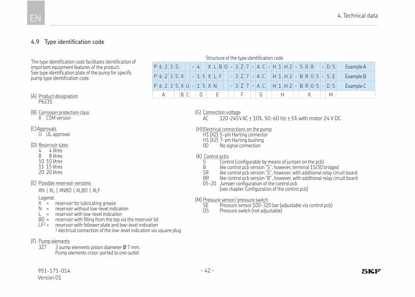
Structure of the type identification code
P 6 2 3 S - 4 X L B O - 3 Z 7 - A C - H 1 .H 2 - S 0 8 - D S Example A
P 6 2 3 S X - 1 5 X L F - 3 Z 7 - A C H 1 .H 2 - B R 0 5 - S E Example B
P 6 2 3 S X U - 1 5 X N - 3 Z 7 - A C H 1 .H 2 - B R 0 5 - D S Example C
A B C D E F G H K M
The type identification code facilitates identification of important equipment features of the product. See type identification plate of the pump for specific pump type identification code.
(A) Product designation P623S
(B) Corrosion protection class X C5M version
(C) Approvals U UL approval
(D) Reservoir sizes 4 4 litres 8 8 litres 10 10 litres 15 15 litres 20 20 litres (E) Possible reservoir versions
XN | XL | XNBO | XLBO | XLF
Legend: X = reservoir for lubricating grease N = reservoir without low-level indication L = reservoir with low-level indication B0 = reservoir with filling from the top via the reservoir lid LF1 = reservoir with follower plate and low-level indication 1 electrical connection of the low-level indication via square plug
(F) Pump elements 3Z7 3 pump elements piston diameter Ø 7 mm. Pump elements cross-ported to one outlet
(G) Connection voltage AC 120-240 V AC ± 10%, 50-60 Hz ± 5% with motor 24 V DC
(H) Electrical connections on the pump H1 (X2) 5-pin Harting connector H1 (X2) 7-pin Harting bushing 00 No signal connection
(K) Control pcb's S Control (configurable by means of jumper on the pcb) B like control pcb version "S“, however, terminal 15/30 bridged SR like control pcb version "S“, however, with additional relay circuit board BR like control pcb version "B“, however, with additional relay circuit board 05-20 Jumper configuration of the control pcb (see chapter Configuration of the control pcb)
(M) Pressure sensor/ pressure switch SE Pressure sensor 100-320 bar (adjustable via control pcb) DS Pressure switch (not adjustable)
4.9 Type identiication code
5
EN5. Delivery, returns, and storage
- 43 - 951-171-014Version 01
5. Delivery, returns, and storage
5.1 Delivery
After receipt of the shipment, check the shipment for damage and completeness according to the shipping documents. Im-mediately report any transport damages to the forwarding agent. Keep the packaging material until any dis-crepancies are resolved. During in-house transport ensure safe handling.
5.2 Returns
Clean all parts and pack them properly (i.e. following the regulations of the recipient country) before returning them. Protect the product against mechanical influences such as impacts. There are no restrictions for land, sea or air transport. Mark returns on the packaging as follows.
5.3 Storage
SKF products are subject to the following storage conditions: ○ dry, dust- and vibration-free in closed
premises
○ no corrosive, aggressive materials at the place of storage (e. g. UV rays, ozone)
○ protected against pests and animals (in-sects, rodents, etc.)
○ possibly in the original product packaging
○ shielded from nearby sources of heat and coldness
○ in case of high temperature fluctuations or high humidity take adequate measures (e. g. heater) to prevent the formation of condensation water.
Before application inspect the products with regard to possible damages occurred during their storage. This particularly applies for parts made out of plastic and rubber (embrittlement).
5.4 Storage temperature range
○ In case of parts not primed with lubri-cant the admissible storage temperature range corresponds to that of the operat-ing temperature of the pump (see Techni-cal data).
○ In case of parts primed with lubricant the admissible storage temperature range is:
min. + 5 °Cmax. +35 °C
If the storage temperature range is not adhered to, the following work steps for replac-ing the lubricant may not in all cases lead to the desired result.

EN 5. Delivery, returns, and storage
- 44 -951-171-014Version 01
5.5 Special storage conditions for parts primed with lubricant
The conditions mentioned in the following will have to be adhered to when storing products primed with lubricant,
5.5.1 Storage period of up to 6 months
The primed products can be used without having to take further measures.
5.5.2 Storage period from 6 to 18 months
Pump• Connect the pump electrically.
• Switch the pump on and let it run, e.g. by triggering an additional lubrication, until about 4 cc of lubricant will leak from each pump element.
• Switch the pump off and disconnect it from the electrical grid.
• Remove and dispose of leaked lubricant.
Single-line metering device• Remove all connection lines and closure
screws, if any.
• Connect the pump primed with new lubrication grease suitable for the appli-
cation purpose to the divider bar in such way that the opposite port of the divider bar remains open.
• Let the pump run until new lubricant leaks from the divider bar.
• Remove leaked lubricant.
• Reinstall closure screws and connection lines.
Lines• Dismantle preassembled lines.
• Ensure that both line ends remain open.
• Prime lines with new lubricant.
Pressure switch/ way valve• Process, see description of single-line
metering devices
5.5.3 Storage period exceeding 18 months
To avoid dysfunctions consult the manufac-turer before commissioning. The general procedure to remove the old grease filling corresponds to that of a storage period from 6 to 18 months.

6
EN6. Assembly
- 45 - 951-171-014Version 01
6. Assembly
6.1 General information
Only qualified technical personnel may install the products described in these Instructions.During assembly pay attention to the following: ○ Other units must not be damaged by the
assembly.
○ The product must not be installed within the range of moving parts.
○ The product must be installed at an ad-equate distance from sources of heat and coldness.
○ Observe the product's IP type of protection.
○ Adhere to safety distances and legal pre-scriptions on assembly and prevention of accidents.
6.2 Place of installation
Protect the product against humidity, dust and vibrations and install it in an easily ac-cessible position to facilitate other installa-tion and maintenance works. Observe the IP protection class.
○ Possibly existing visual monitoring de-vices, e.g. pressure gauges, MIN/MAX markings or piston detectors, must be clearly visible.
○ Observe prescriptions in the Technical data (chapter 4) regarding the installation position.

EN 6. Assembly
- 46 -951-171-014Version 01
Minimum assembly dimensions Fig. 76.3 Mechanical connection
6.3.1 Minimum assembly dimensions
Ensure sufficient space for maintenance or repair work or for assembly of further components of the centralized lubrication system by leaving a free space of at least 100 mm into each direction in addition to the stated dimensions.
Minimum installation dimensions in mm
4 l 8 l 10 l 15 l 20 l
A1 498 598 658 841 976
A2 439 539 599 782 917
B 220
C 278
B
A1
C
A2

6
EN6. Assembly
- 47 - 951-171-014Version 01
Installation bores Fig. 86.3.2 Installation bores
Pumps with 4 l and 8 l reservoirs: Are fastened at the two lower mounting points (A).
Pumps with 10 l, 15 l and 20 l reservoirs: Are fastened at the two lower mounting points (14) and additionally a the two upper mounting points (15).
NOTICE
Risk of damage to the superior machine and to the pumpDrill the mounting bores on non-load-bearing parts of the superior machine only.Fastening must not be done on two parts moving against one another (e. g. ma-chine bed and machine assembly). Flat-ness of the upper and lower mounting faces to each other must not deviate by more than 1 mm.
Mounting bores in mm
4 l 8 l 10 l 15 l 20 l
A 11 11 11 11 11
B 180 180 180 180 180
C 177.5 177.5 177.5 177.5 177.5
D 10.4 10.4 10.4
E 160 160 160
F 367.5 550.5 685.5
Fastening is done by means of:2 resp. 4 screws M10 (8.8)2 resp. 4 hexagon nuts M10 (8.8)2 resp. 4 washers 10CTightening torque = 25 Nm ± 1 Nm
15
A
B
F
C
E
D
1.0
14

EN 6. Assembly
- 48 -951-171-014Version 01
Electrical connection, Fig. 96.4 Electrical connection
WARNING
Electric shockMake sure to disconnect the product from the power supply before carrying out any works on electrical components.
Connect the cables in such way that no mechanical forces are transferred to the product.
For connection proceed as follows:• Connect and lock the plug (6.1) for the
signal connection.
• Connect and lock the plug (6.2) for the voltage supply.
• Where applicable, connect the plug (6.3) for the low-level indication.
• If needed, connect the equipotential bonding connection on the housing (6.4) with the equipotential bond-ing connection of the superordinate machine.
6.1
6.2
6.4
6.3

6
EN6. Assembly
- 49 - 951-171-014Version 01
6.5 Lubrication line connection
CAUTION
Risk of fallingExercise care when dealing with lubricants. Immediately absorb and remove and leaked lubricant.
Connect lubrication lines in such way that no forces are trans-ferred to the product (tension-free connection).
All components of the centralized lubrica-tion system must be laid out for: ○ the maximum arising pressure
○ the admissible temperature range
○ the output volume and the lubricant to be supplied.
Protect the centralized lubrica-tion system against too high pressure by means of a suitable pressure relief valve.
○ The lubricant flow should not be impeded by the installation of sharp elbows, angle valves, gaskets protruding to the inside, or cross-section changes (big to small). Provide unavoidable changes of the cross sections in the lubrication lines with as smooth transitions as possible.
Observe the following installation instruc-tions for safe and smooth operation. ○ Use clean components and primed lubri-
cation lines only.
○ The main lubrication line should be laid preferably rising with a possibility to vent it at its highest point. Lubrication lines shall generally be laid in such way that there can never be created air pockets at any point.
○ Mount the lubricant metering devices at the end of the main lubrication line in such way that the outlets of the lubricant metering devices show upwards.
○ If lubricant metering devices have to be mounted below the main lubrication line, then this should not be done at the end of the main lubrication line.
EN 6. Assembly
- 50 -951-171-014Version 01
6.6 Programming
To program the pump proceed according to the following programming scheme.
• Simultaneously press key 19 and key 20 for more than 4 seconds to access the first programming step P1.
After releasing the keys the adjusted value will be displayed.
• Change the value of the programming step by pressing key 20.
• Confirm adjusted value within 30 seconds by pressing key 19. Otherwise the value will be lost.
• Programming is continued with pro-gramming step P2.
After confirming the last step P8 the pro-gramming is completed.
6.6.1 Legend of the programming scheme
Program functionsP1/ P2 Setting of the pause time in hoursP1/ P2 Setting of the pause time in minutesP4 Setting of the output signal on the monitoring relayP5 Setting of the differentiation between fault and low-level signalP6 Setting of the start stageP7 Adjusting the operating pressureP8 Adjusting the relief pressure
A = Programming stepB = Possible valueC = Change value by pressing the shown key 20.D = Possible new value E = Confirm adjusted value within 30 sec-onds by pressing key 19 and continue with the next programming step. Confirm and finish the programming by pressing key 20 after the last programming step.
Notes related to the programmingSettings can be done in one direction only (+) Fast forward by holding down key 20.

6
EN6. Assembly
- 51 - 951-171-014Version 01
Programming scheme P623S Fig. 10
min h
On
min h
On
min h
On
min h
On
min h
On
min h
On
min h
On
min h
On
min h
On
&
> 4 S
20 A B C
min h
On
D E19
min h
On
min h
On
min h
On
min h
On
min h
On
min h
On
min h
On
min h
On
min h
On
min h
On
19
(OR)
min h
On
min h
On
On

EN 6. Assembly
- 52 -951-171-014Version 01
6.6.2 Filling via iller itting• Place filling connection of the filler pump
onto filler fitting R1/4 (5).
• Switch on filler pump and fill reservoir with lubricant until shortly below the MAX marking.
• Switch the filler pump off and remove it from the filler fitting (5) of the pump.
Filling via filler fitting Fig. 11
5

6
EN6. Assembly
- 53 - 951-171-014Version 01
6.6.3 Filling via the reservoir lid in case of pumps without follower plate
WARNING
Crushing hazardon the rotating stirring paddle. Fill-ing via the reservoir lid is allowed only after disconnecting the pump from the power supply by remov-ing it from the connection (6.2).
• Unscrew the reservoir lid (1.2) anti-clockwise from the reservoir. Deposit the reservoir lid at a clean place. The reservoir lid must not be contaminated. Remove possible contaminations from the reservoir lid.
• Fill the reservoir from the top up to the MAX marking. Make sure to fill in the lu-bricant without air inclusions, if possible.
• Reinstall the reservoir lid (1.2) clockwise.
Filling via the reservoir lid Fig. 12
1.2
6.2

EN 7. Initial start-up
- 54 -951-171-014Version 01
7. Initial start-up
Start-up check list
7.1 Inspections prior to initial start-up YES NO
Electrical connection carried out correctly.
Mechanical connections carried out correctly
Pump filled with the planned lubricant
The performance data of the previously indicated connections correspond to the specifications stated in the Technical data.
All components, such as lubrication lines and metering devices, have been correctly installed.
Product protected with adequate pressure relief valve
No visible damage, contamination and corrosion
Any dismantled protection and monitoring equipment has been reassembled and checked for correct function
Earth strap fully present, properly connected and electrically conductive
7.2 Inspections during initial start-up
No unusual noises, vibrations, accumulation of moisture, or odours present
No unwanted escape of lubricant from connections
Bearings and friction points to be lubricated are provided with the planned amount of lubricant.
In order to warrant safety and function, a person assigned by the operator must carry out the following inspections. Remedy detected de-fects before the initial start-up. Deficiencies may be remedied by an authorized and qualified specialist only.

8
EN8. Order
- 55 - 951-171-014Version 01
8. Order
SKF products operate automatically to the greatest possible extent. Basically, activities during standard opera-tion are limited to the control of the filling level and the timely refilling of lubricant as well as the outside cleaning of the product in case of contamination. Furthermore it is possible to query the ad-justed parameters in the query mode.
8.1 Reill lubricantDescription see corresponding chapter.
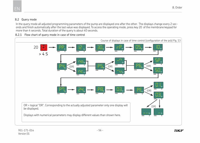
EN 8. Order
- 56 -951-171-014Version 01
8.2 Query mode
In the query mode all adjusted programming parameters of the pump are displayed one after the other. The displays change every 2 sec-onds and finish automatically after the last value was displayed. To access the operating mode, press key 20 of the membrane keypad for more than 4 seconds. Total duration of the query is about 40 seconds.
Course of displays in case of time control (configuration of the pcb) Fig. 13
> 4 S
min h
On
min h
On
h
On
min
(OR)min h
On
min h
On
h
On
min
(OR)min h
On
min h
On
h
On
min
(OR)
min h
On
min h
On
min h
On
min h
On
min h
On
min h
On
min h
On
h
On
min min h
On
h
On
min
min h
On
min h
On
(OR)min h
On
(OR)
min h
On
min h
On
20
OR = logical "OR“. Corresponding to the actually adjusted parameter only one display will be displayed.
Displays with numerical parameters may display different values than shown here.
8.2.1 Flow chart of query mode in case of time control

8
EN8. Order
- 57 - 951-171-014Version 01
Course of displays in case of pulse control (configuration of the pcb) Fig. 14
> 4 S
min h
On
min h
On
h
On
min
(OR)min h
On
min h
On
h
On
min
(OR)min h
On
min h
On
h
On
min
(OR)
min h
On
min h
On
min h
On
min h
On
min h
On
min h
On
min h
On
h
On
min min h
On
h
On
min
min h
On
min h
On
(OR)min h
On
(OR)
min h
On
min h
On
x 100 x 1 x 100 x 1+ +
20
OR = logical "OR“. Corresponding to the actually adjusted parameter only one display will be displayed.The displayed values correspond to the number of displayed pulses (multiplied by 100 resp. multiplied by 1)
8.2.2 Flow chart of query mode in case of pulse control

EN 9. Cleaning
- 58 -951-171-014Version 01
9. Cleaning
WARNING
Electric shockCarry out cleaning works only on depressurized products that have been disconnected from the power supply. Do not touch cables or electrical components with wet or damp hands. Use steam-jet cleaners or high-pressure cleaners only in accordance with the IP protection class of the pump. Otherwise electrical components may be damaged. Cleaning execution, required personal protective equipment, cleaning agents and devices following the valid operational regulations of the operator.
9.1 Cleaning agents
Cleaning agents compatible with the mate-rial may be used only (materials, see chap-ter 2.3).
Thoroughly remove residues of cleaning agents from the product and rinse off with clear water.
9.2 Exterior cleaning
Make sure to keep the reser-voir closed during the cleaning procedure.
• Mark and secure wet areas.
• Keep unauthorized persons away.
• Thorough cleaning of all outer surfaces with a damp cloth.
9.3 Interior cleaning
Normally, interior cleaning is not required. Should incorrect or contaminated lubricant have been filled, inside cleaning of the prod-uct will be required. To do so, contact the SKF Customer Service.

10
EN10. Maintenance
- 59 - 951-171-014Version 01
10. MaintenanceRegular and appropriate maintenance is a prerequisite to detect and clear faults in time. As it is not possible for us to exactly define the operating conditions, we cannot indicate any definite deadlines. The specific timelines have to be determined, verified at regular intervals and adapted, if necessary, by the operator based on the local operating conditions. If needed, copy the table for regular maintenance activities.
Maintenance check list
Activity to be done YES NO
Electrical connection carried out correctly.
Mechanical connections carried out correctly
The performance data of the previously indicated connections correspond to the specifications stated in the Technical data.
All components, such as lubrication lines and metering devices, have been correctly installed.
Product protected with adequate pressure relief valve
No visible damage, contamination and corrosion
Any dismantled protection and monitoring equipment has been reassembled and checked for correct function
All warning labels on the product are available and in proper condition.
No unusual noises, vibrations, accumulation of moisture, or odours present
No unwanted escape of lubricant from connections
Bearings and friction points to be lubricated are provided with the planned amount of lubricant.
Earthing cable fully present, properly connected and electrically conductive.

EN 11. Troubleshooting
- 60 -951-171-014Version 01
11. Troubleshooting
Fault table 1
Fault signal(flashing)
Possible cause Remedy
Low level indicationThe ongoing lubrication cycle will still be completed. An auto-matic restart will take place after filling only. However, an ad-ditional lubrication is possible.
Fill the reservoir with the specified lubricant
Fault signal E1Fault of pressurization (internal pressure control). Pressure P1 was not reached within the monitoring time.
Check the system. May be the operating pressure must be reduced
Fault signal E2Fault of pressurization (internal or external pressure control). Pressure P1 or P2 was not reached within the monitoring time.
Check the system. May be the operating pressure must be reduced
Fault signal E3Fault of pressure relief (internal pressure control). Pressure P1R was not undercut within the monitoring time.
1. Triggering an additional lubrication. The motor rotates in the direction of the relief (10 sec.) After a successful relief, the fault signal will disappear2. If there is no pressure relief: Reduce the system pressure and carry out step 1 once again
If fault signal continues: Check relief device or inform our Cus-tomer Service
Fault signal E4Fault of pressure relief (external pressure control). Pressure P2R was not undercut within the monitoring time.
Fault signal EPA fault of the membrane keypad or the display is pending.
Replace membrane keypad

11
EN11. Troubleshooting
- 61 - 951-171-014Version 01
Fault table 2
Fault Possible cause Remedy
Pump does not runDisplay is off
- Power supply to the pump is interrupted
- Superior machine is switched off
- Connection cable of pump is loose or defective
- External fuse is defective
- Pump supply board of pump is defective
- Printed circuit board of pump is defective
Check whether one of the indicated faults is present and rem-edy it in the frame of your responsibilities.
Faults outside of your own responsibility have to be reported to your superior to initiate further measures.
If the fault cannot be determined and remedied, please con-tact our Customer Service.
Pump runs but supplies no or only little lubricant
- air pockets in the lubricant
- suction bore of a pump element is clogged
-worn pump element
- too high lubricant consistency (at low temperatures)
- too low lubricant consistency (at high temperatures)
Check whether one of the indicated faults is present and rem-edy it in the frame of responsibilities.
Faults outside of your own responsibility have to be reported to your superior to initiate further measures.
If the fault cannot be determined and remedied, please con-tact our Customer Service.

- 62 -951-171-014Version 01
EN 12. Repairs
12. Repairs
12.1 Check pump element and replace pressure control valve.
The characteristics of the new pump element must correspond to the characteristics of the pump element to be replaced (see spare parts).
To replace the pump element, proceed as follows:
• Unscrew the defective pump element (4) at its hexagon out of the pump housing together with the pressure control valve (11).
• Screw the new pump element (4) into the pump housing together with a new gasket.
Tightening torque = 40 Nm ± 2.0 Nm• Then screw a new pressure relief valve
(9) into the pump element.
Tightening torque = 8 Nm + 0.8 Nm
WARNING
Risk of injuryBefore carrying out any repair work, take at least the following safety measures: ○ Keep unauthorized persons
away.
○ Mark and secure work area.
○ Depressurize the product.
○ Disconnect the product from the power supply and secure it against being switched on.
○ Verify that no power is being applied
○ Earth and short-circuit the product.
○ Where needed, cover neighbour-ing units that are live.
The work described should possibly be done at room tem-perature. At low temperatures the work may be subject to restrictions.
Replace pump element Fig. 15
4
11

12
- 63 - 951-171-014Version 01
EN12. Repairs
12.2 Replace membrane keypad
To replace the membrane keypad proceed as follows:
• Check the new membrane keypad for ac-cordance with the documentation and the intended purpose.
• Implement the safety measures as speci-fied in the warning notice at the begin-ning of this chapter.
• Take protection measures against elec-trostatic discharge.
• Turn screws (3.1) out of the housing front cover (3). Remove housing front cover (3) from pump housing. Keep parts for further use.
• Unscrew the control pcb (12) at the two screws (12.1).
• Carefully tilt the control pcb (12) upward until the connection for the membrane keypad (17.1) becomes visible.
• Loosen the plug of the membrane keypad (17.1) on the control pcb (see Fig. 18).
Remove the housing front cover Fig. 16
3.1
3
Housing front cover removed Fig. 17
12.1
12
3.1

- 64 -951-171-014Version 01
EN 12. Repairs
• Carefully loosen and remove the mem-brane keypad (17) forward from the housing.
• Guide the plug (17.1) of the new mem-brane keypad (17) from the front through the opening on the housing front cover and plug it onto the corresponding port of the control pcb. Ensure that the plug is oriented correctly.
• Carry out the assembly in the reverse order to the disassembly.
Tightening torque of the screws of the housing front cover = 2.5 Nm + 0.1 Nm.
Remove the housing front cover Fig. 20
17
Connect the plug of the membrane keypad Fig. 19
17.1
Loosened plug of the membrane keypad Fig. 18
17.1

12
- 65 - 951-171-014Version 01
EN12. Repairs
12.3 Replace control printed circuit board
To replace the control pcb proceed as follows:
• Check the new control pcb for accordance with the documentation and the intended purpose.
• Implement the safety measures as speci-fied in the warning notice at the begin-ning of this chapter.
• Take protection measures against elec-trostatic discharge.
• Unscrew the screws (3.1) from the hous-ing front cover (3). Remove the housing front cover from pump housing. Keep parts for further use.
• Carefully loosen all plugs (12.2) of the control pcb (12).
• Note down the set-up and position of the plugs or mark plugs accordingly.
• Open the reservoir lid (12) on the two screws (12.1) and remove it.
• Carefully loosen the plug (17.1) of the membrane keypad.
Remove the control pcb 22Remove the housing front cover Fig. 21
3.1
3
12.1
12
3.1
12.2
Loosen the plug of the membrane keypad Fig. 23
17.1
• Carry out the assembly in the reverse order to the disassembly.
Tightening torque of the screws of the housing front cover = 2.5 Nm + 0.1 Nm.
12

- 66 -951-171-014Version 01
EN 12. Repairs
12.4 Replace relay circuit board
To replace the relay circuit board proceed as follows:
• Check the new relay circuit board for ac-cordance with the documentation and the intended purpose.
• Implement the safety measures as speci-fied in the warning notice at the begin-ning of this chapter.
• Take protection measures against elec-trostatic discharge.
• Unscrew the screws (3.1) from the hous-ing front cover (3). Remove the housing front cover from the pump housing. Keep parts for further use.
• Carefully loosen all plugs (13.2) of the relay circuit board (13).
• Loosen the relay circuit board (13) on the two screws (13.1) and remove it.
• Carry out the assembly in the reverse order to the disassembly.
Remove relay circuit board Fig. 25Remove the housing front cover Fig. 24
3.1
3
13.1
13
3.1
13.2
Tightening torque of the screws of the housing front cover = 2.5 Nm + 0.1 Nm.

12
- 67 - 951-171-014Version 01
EN12. Repairs
12.5 Replace power supply board
To replace the power supply board proceed as follows:
• Check the new power supply board for accordance with the documentation and the intended purpose.
• Implement the safety measures as speci-fied in the warning notice at the begin-ning of this chapter.
• Take protection measures against elec-trostatic discharge.
• Unscrew the screws (3.1) from the hous-ing front cover (3). Remove the housing front cover from the pump housing. Keep parts for further use.
• Loosen the relay circuit board (13) on the two screws (13.1) and remove it upwards together with the housing front cover and the control pcb.
• Loosen and remove the plug (13.2) between the relay circuit board and the power supply board (14) by carefully lift-ing the lock.
Remove relay circuit board Fig. 27Remove housing front cover Fig. 26
3.1
3
13.1
13
3.113.2
Removed relay circuit board Fig. 28
13.2 14
• Carefully pull the power supply board (14) forward and out of the two lateral guide rails (14.1) and out of the housing.

- 68 -951-171-014Version 01
EN 12. Repairs
• Place new power supply board in the lat-eral guide rails (14.1) and push it into the housing until you notice resistance.
• Then push power supply board forward until the front edge of the power sup-ply board fits flush with the guide rails. The power supply board is in the correct mounting position.
• Carry out the assembly in the reverse order to the disassembly.
Tightening torque of the screws of the housing front cover = 2.5 Nm + 0.1 Nm.
Power supply board mounted correctly Fig. 32
Correct
14.1 14.1
Power supply board moun-ted incorrectly Fig. 31
14.114.1
Wrong
Power supply board Fig. 29
Removed power supply board Fig. 30
14.1 14.114

12
- 69 - 951-171-014Version 01
EN12. Repairs
12.6 Tests after replacement of the power supply board
After replacement of the power supply board carry out an electrical test acc. to EN 60204-1 in the fol-lowing order:
12.6.1 Visual check
○ Housing front cover mounted properly. No visible damages to the pump.
12.6.2 Electrical safety test
Use measuring equipment following EN 61557 for the mentioned electrical
tests. ○ Testing the protective conductor system
with regard to conductivity.
○ Insulation test (terminals L and N bridged against PE).
12.6.3 Electrical functionality test
The electrical function test must be carried out immediately after the repair following the protection class of the electrical appara-tus to be tested. The electrical function test may be carried out by a trained electrician observing the statutory provisions and per-tinent regulations.
FilingAfter the replacement of the power supply board the scope and findings of the test have to be recorded in writing and handed over for filing to the person responsible for machine operation.

EN 13. Shutdown and disposal
- 70 -951-171-014Version 01
13. Shutdown and disposal
13.1 Temporary shutdown
Temporarily shut the system down by: ○ switching off the superior machine.
○ Disconnecting the product from the power supply.
13.2 Final shutdown and disassembly
The final shutdown and disassembly of the product must be professionally planned and carried out by the operator in compliance with all regulations to be observed.
13.3 Disposal
Countries within the European Union
Disposal should be avoided or minimized wherever possible. Disposal of products contaminated with lubricant must be effect-ed via a licensed waste disposal contractor in accordance with environmental require-ments and waste disposal regulations as well as local authority requirements.
The specific classification of the waste is in the waste producer's responsibility, as the European Waste Catalogue provides differ-ent waste disposal codes for the same type of waste but of differ-ent origin.
Dispose of or recycle electrical
components following WEEE
directive 2012/19/EU.
Parts made of plastic or metal
can be disposed of with the
commercial waste.
Countries outside the European Union
The disposal has to be done according to the valid national regulations and laws of the country where the product is used.
EN14. Spare parts
14
- 71 - 951-171-014Version 01
14. Spare parts
The spare parts assemblies may be used exclusively for replacement of identical defective parts. Modifications with spare parts on existing products are not allowed.
Fig. 3314.1 Housing front cover, assy.
Designation Qty. Part number
Consisting of: 1 x housing front cover 1 x profile seal 1 x membrane keypad 4 x screw with washer
1 545-60168-1
Onmin
h
Fig. 3414.2 Pump element Z7
Designation Qty. Part number
Pump element Z7 including sealing ring 1 645-29818-1
Fig. 3514.3 Pressure control valve
Designation Qty. Part number
Consisting of:1 x pressure control valve SVTS-400-R 1/4A-D10
1 624-77641-1

EN 14. Spare parts
- 72 -951-171-014Version 01
1
2
3
4
Fig. 3614.4 Control pcb
Designation Qty. Part number
Consisting of: 1 x control pcb 1 x profile seal 4 x screw with washer
1 545-60169-1
Fig. 3714.5 Relay circuit board
Designation Qty. Part number
Consisting of:1 x relay circuit board 1 x profile seal 4 x screw with washer
1 545-60170-1
Fig. 3814.6 Power supply board
Designation Qty. Part number
Consisting of:1 x power supply board 1 x profile seal 4 x screw with washer
1 545-60171-1
EN15. Electrical connections / wiring diagrams
15
- 73 - 951-171-014Version 01
15. Electrical connections
15.1 Cable colours following IEC60757
Abbreviation Colour Abbreviation Colour Abbreviation Colour Abbreviation Colour
BK black GN green WH white PK pink
BN brown YE yellow OG orange TQ turquoise
BU blue RD red VT violet
15.2 Wire allocation of the connectors
For wire allocation of the connectors see the corresponding cir-cuit diagram of these instructions
Connector H1 / X2 Connector H2 / X4
15.3 Assignment of the circuit diagrams to the pump type identiication codeAssignment of the circuit diagrams to a certain pump is done via the characteristics given in the type identification code (see type identification code in these instructions).
Characteristic A Product designation
Characteristic E Reservoir version
Characteristic G Connection voltage
Characteristic H Electrical connections
Characteristic K Control pcb
If the indications of the type identification code correspond to those of the circuit diagram, then the circuit diagram applies. See type identification plate of the pump for specific pump type identification code.

EN 15. Electrical connections / wiring diagrams
- 74 -951-171-014Version 01
15.4 Connection diagram P623S-PCB-M-DS-DT-SN-H1
Connection diagram P623S-PCB-M-DS-DT-SN-H1 Fig. 39
DS
M
Display/Taster
PE
SN
X2
PCB
X6
X7
X3X9
X10 X11
X12 X13
X14 X15
X17
X19 X18
X28
X29
X30X31
1 14
13
12
2
3
M-
M+
-
+
E1
30
31
ErON15
1
2
PE
3
4
5
L
N
PE
1
2
1 2
1
2 8
9
X43
X45-
+E2
X47
Z
L1
N
PE
1
2
3
4
+
+ -
H3.
1-R
D-1
00m
m-A
WG
18
H3.
2-B
N-1
00m
m-A
WG
18
H9-
GN
YE-
240m
m-A
WG
18
H15
.3-G
NY
E-40
0mm
-1m
m²
H15
.2-B
K
2-18
0mm
-1m
m²
H15.1-BK 1- 180mm-1mm²
H15-3G1-
H7
H5
H4.2-RD-350mm-AWG18
H4.1-BN-350mm-AWG18
H11-GNYE-165mm-AWG18
Res.
120
Status: 2015.07.28
Valid for type identification codes with the following characteristicsP 6 2 3 S X N - A C - H 1 - SP 6 2 3 S X L N - A C - H 1 - B
A E G H K

EN15. Electrical connections / wiring diagrams
15
- 75 - 951-171-014Version 01
15.5 Connection diagram P623S-PCB-M-DS-DT-SN-H1-H2-LLC
Connection diagram P623S-PCB-M-DS-DT-SN-H1-H2-LLC Fig. 40
7
H11-GNYE-165mm-AWG18
H18-GNYE-370mm-AWG18
H2.2-YE-AWG18
H2.1-GN-AWG18
H8-RD-AWG18
H10.2-BK-AWG18
H10.3-BN-AWG18
H10.1-RD-AWG18
H3.
1-R
D-1
00m
m-A
WG
18
H3.
2-B
N-1
00m
m-A
WG
18
H9-
GN
YE-
240m
m-A
WG
18
H15
.3-G
NY
E-40
0mm
-1m
m²
H15
.2-B
K
2-18
0mm
-1m
m²
H15.1-BK 1- 180mm-1mm²
H15-3G1-
7Res.
DS
M
Display/Taster
PE
SN
X4
X2
PCB
X6
X7
X3X9
X10 X11
X12 X13
X14 X15
X16
X17
X19 X18
X28
X29
X30X31
1 14
13
12
2
3
M-
M+
-
+E1
30
31
ErON15
1
2
PE
4
5
6
1
2
3
3
4
5
L
N
PE
1
2
1 2
PE
1
2 8
9
X42 X4310
11
X44 X4517
16
15
-
+E2
X46 X47
Z6
+out
-out
E2
LC
ON +
F +
PE
L1
N
PE
543
1
2
3
4
+
+ -
X33LLC
H7
H5
H4.2-RD-350mm-AWG18
H4.1-BN-350mm-AWG18
H12
120
Status: 2015.07.28
Valid for type identification codes with the following characteristicsP 6 2 3 S X L - A C - H 1 .H 2 - SP 6 2 3 S X L B 0 - A C - H 1 .H 2 - B
A E G H K

EN 15. Electrical connections / wiring diagrams
- 76 -951-171-014Version 01
15.6 Connection diagram P623S-PCB-M-DS-DT-H1-H1-LLC-RPCB
Connection diagram P623S-PCB-M-DS-DT-H1-H2-LLC-RPCB Fig. 41
H6.1-YE-100mm-AWG18
H6.2-GN-100mm-AWG18
H12
7 Res.
H14.1-WH-270mm-AWG18
H11-GNYE-165mm-AWG18
H18-GNYE-370mm-AWG18
H14.2-YE-270mm-AWG18
H14.3-GN-270mm-AWG18
H8-RD-AWG18
H10.2-BK-AWG18
H10.3-BN-AWG18
H10.1-RD-AWG18
H7
H5
H4.2-RD-350mm-AWG18
H4.1-BN-350mm-AWG18H
3.1-
BK-
100m
m-A
WG
18
H3.
2-B
U-1
00m
m-A
WG
18
H15-3G1-
H3.
3-B
K-10
0mm
-AW
G18
H3.
4-B
U-1
00m
m-A
WG
18
H9-
GN
YE-
240m
m-A
WG
18
H15
.3-G
NY
E-40
0mm
-1m
m²
H15
.2-B
K
2-18
0mm
-1m
m²
H15.1-BK 1- 180mm-1mm²
+out
-out
E2
LC
ON +/-
F +/-
+/-
PE
L1
N
PE543
1
2
3
4
+
+ -
X33LLC
DS
M
Display/Taster
PE
RPCB
SN
X4
X2
PCB
X6
X7
X3X9
X10 X11
X12 X13
X14 X15
X16
X17
X19 X18
X20
X21
X23 X22
X25 X24
X26
X27
X28
X29
X30X31
1 14
13
12
2
3
M-
M+
-
+
E1
30
31
ErON15
1
2
PE
4
5
6
1
2
3
3
4
5
L
N
PE
1 23
ErON
X4
X3
321
1
2
3
1
2
3
X5
321 321 321X1X6 X7
X34
X35X37
X36
321 321 321
7
1
2
1 2
PE
1
2 8
9
X38
X39
321X2
321
X42 X4310
11
X48
X49
321X8
321
X44 X4517
16
15
-
+
E2
X46 X47Z6
120
Status: 2015.07.28
Valid for type identification codes with the following characteristicsP 6 2 3 S X L - A C - H 1 .H 2 - S RP 6 2 3 S X L B 0 - A C - H 1 .H 2 - B R
A E G H K

EN15. Electrical connections / wiring diagrams
15
- 77 - 951-171-014Version 01
15.7 Connection diagram P623S-PCB-M-DS-DT-SN-H1-H2-LF
Connection diagram P623S-PCB-M-DS-DT-SN-H1-H2-LF Fig. 42
H15-3G1- HELKUKABEL-JZ602-
Best. Nr. 83081
7 Res.
H13-4xAWG22-~970mm- Tube inside Ø10mm
X44
X42
DS
M
Display/Taster
PE
LM
SN
X4
X2
PCB
X6
X7
X3
X8 X1
M12x1
X9
X10 X11
X12 X13
X14 X15
X16
X17
X19 X18
X28
X29
X30X31
X32X33
M12x1 Schaltstange
1 14
13
12
2
3
M-
M+
-
+
E1
30
31
ErON15
1
2
3
1
2
PE
4 4
5
6
1
2
3
3
4
5
1
2
3
4
1
2
3
4
1
2
3
4
L
N
PE
7
1
2
1 2
PE
1
2 8
9
X40
X41
12
X4310
11
X4517
16
15
-
+
E2
+out
-out
X46 X47Z6
E2
LC
ON +
F +
PE
L1
N
PE
H2.2-YE-AWG18
543
1
2
3
4
+
+ -
12
H2.1-GN-AWG18
H8-RD-AWG18
H10.2-BK-AWG18
H10.3-BN-AWG18
H10.1-RD-AWG18
H11-GNYE-165mm-AWG18
H1.4-BU-50mm-
AWG18
H7
H5
H4.2-RD-350mm-AWG18
H4.1-BN-350mm-AWG18H1.1-BK-AWG18
H1.2-RD-AWG18
H1.3-BN-50mm-AWG18
H3.
1-R
D-1
00m
m-A
WG
18
H3.
2-B
N-1
00m
m-A
WG
18
H9-
GN
YE-
240m
m-A
WG
18
H15
.3-G
NY
E-40
0mm
-1m
m²
H15
.2-B
K
2-18
0mm
-1m
m²
H15.1-BK 1- 180mm-1mm²
H18-GNYE-370mm-AWG18
120
Status: 2015.07.28
Valid for type identification codes with the following characteristicsP 6 2 3 S X L F - A C - H 1 .H 2 - SP 6 2 3 S X L F - A C - H 1 .H 2 - B
A E G H K

EN 15. Electrical connections / wiring diagrams
- 78 -951-171-014Version 01
15.8 Connection diagram P623S-PCB-M-DS-DT-H1-H1-LF-RPCB
Connection diagram P623S-PCB-M-DS-DT-SN-H1-H1-LF-RPCB Fig. 43
X9
3
H14.2-YE-270mm-AWG18
H14.3-GN-270mm-AWG18
H8-RD-AWG18
H10.2-BK-AWG18
H10.3-BN-AWG18
H10.1-RD-AWG18
H14.1-WH-270mm-AWG18
H6.1-YE-100mm-AWG18
H6.2-GN-100mm-AWG18
H1.1-BK-AWG18
H1.2-RD-AWG18
H1.4-BU-50mm-AWG18
H1.3-BN-50mm-AWG18H13-4xAWG22-~970mm-
Tube inside Ø10mm
7 Res.
H3.
3-B
K-10
0mm
-AW
G18
H3.
4-B
U-1
00m
m-A
WG
18
H9-
GN
YE-
240m
m-A
WG
18
H15
.3-G
NY
E-40
0mm
-1m
m²
H15
.2-B
K
2-18
0mm
-1m
m²
H15.1-BK 1- 180mm-1mm² H15-3G1-
H3.
1-B
K-10
0mm
-AW
G18
H3.
2-B
U-1
00m
m-A
WG
18
DS
M
Display/Taster
PE
RPCB
LM
SN
X4
X2
PCB
X6
X7
X3
X8 X1
X10 X11
X12 X13
X14 X15
X16
X17
X19 X18
X20
X21
X23 X22
X25 X24
X26
X27
X28
X29
X30X31
X32X33
M12x1 Schaltstange
1 14
13
12
2
3
M-
M+
-
+
E1
30
31
ErON15
1
2
3
1
2
PE
4 4
5
6
1
2
3
3
4
5
1
2
3
4
1
2
3
4
1
2
3
4
L
N
PE
1 23
ErON
X4
X3
321
1
2
3
1
2
3
X5
321 321 321X1X6 X7
X34
X35X37
X36
321 321 321
7
1
2
1 2
PE
1
2 8
9
X38
X39
21X2
321
X40
X41
12
X42 X4310
11
X48
X49
321X8
321
X44 X4517
16
15
-
+
E2
X46 X47
Z6
+out
-out
E2
LC
ON +/-
F +/-
+/-
PE
L1
N
PE543
1
2
3
4
+
+ -
12
H7
H5
H4.2-RD-350mm-AWG18
H4.1-BN-350mm-AWG18
H18-GNYE-370mm-AWG18
H11-GNYE-165mm-AWG18
120
M12x1
Status: 2015.07.28
Valid for type identification codes with the following characteristicsP 6 2 3 S X L F - A C - H 1 .H 2 - S RP 6 2 3 S X L F - A C - H 1 .H 2 - B R
A E G H K

EN15. Electrical connections / wiring diagrams
15
- 79 - 951-171-014Version 01
15.9 Functional low chart P623S with internal pressure sensor/ pressure switch
End of pause time/ start of lubrication
Monitoring time of pressurization
lapsed?
Pump ON/ clockwise rotation
Pressure P1 reached?
Pump OFF
Holding time 1 lapsed?
Pressure P1R exceeded?
Pressure P1R exceeded?
NO
NO YES NO
Fault pressurization
Fault pressurization
End of lubrication/ start of pause time
Pump ON/ anticlockwise
rotation
Monitoring time of pressure relief
lapsed?
Pump OFF YES
YES
YES
NO
NO
Holding time 2 lapsed?
YES
NO
YES
Pressure P1R undercut? NO
NO
YESPressure P1R
undercut? YES
YES
En
dS
tart
Pre
ssu
riza
tion
Fau
ltP
ress
ure
rel
ief
YES
YES
NO

EN 15. Electrical connections / wiring diagrams
- 80 -951-171-014Version 01
15.10 Functional low chart P623S with internal and external pressure sensor/ pressure switch
End of pause time/ start of lubrication
Monitoring time of pressurization
lapsed?
Pump ON/ clockwise rotation
Pressure P1
reached?
Pump OFF
Holding time 2 lapsed?
Pressure P1R exceeded?
NO
NO YES
NO
Fault pressurization
Fault pressurization
End of lubrication/ start of pause time
Pump ON/ anticlockwise rotation
Monitoring time of pressure relief
lapsed?
Pump OFF YES
YES
YES
YES
NO
Pressure P1R undercut? NO
NO
YESPressure P1R
undercut? YES
En
dS
tart
Pre
ssu
riza
tion
Fau
ltP
ress
ure
rel
ief
YES
NO
Holding time 1 lapsed?
Pressure P1R exceeded?
NO
YES
Pressure P1R exceeded?
Holding time 3 lapsed?
Pressure P2R exceeded?
Pressure P2R exceeded?
YES
YES
YES
Pressure P2R exceeded?NO
NO
NO
YES
NO
NO
YES
YES
NO

Notes

951-171-014-EN
Version 01
2016/03/14
SKF Lubrication Systems Germany GmbH Walldorf Facilities Heinrich-Hertz-Str. 2-8 DE - 69190 Walldorf Phone: +49 (0) 6227 33-0 Fax: +49 (0) 6227 33-259 E-mail: [email protected] www.skf.com/lubrication
Seals
MechatronicsServices
Lubrication systems
Bearingsand bearing
units
The Power of Knowledge EngineeringDrawing on five areas of competence and application-specific expertise amassed over more than 100 years, SKF brings innovative solutions to OEMs and production facilities in every major industry world-wide. These five areas of competence include bearings and bearing units, seals, lubrication systems, me-chatronics (combining mechanics and electronics into intelligent systems), and a wide range of services, from 3-D computer modelling to advanced condition monitoring and reliability and assessment man-agement systems. A global presence provides SKF customers uniform quality standards and worldwide product availability.
!Important information on product usageAll products from SKF may be used only for their intended purpose
as described in this brochure and any instructions. Not all lubricants are suitable for use in centralized lubrication systems. SKF does offer an inspec-
tion service to test customer supplied lubricant to determine if it can be used in a centralized lubrica-tion system. SKF lubrication systems or their components are not approved for use with gases, liquefied gases, pressurized gases in solution and fluids with a vapour pressure exceeding normal atmospheric pres-sure (1013 mbar) by more than 0.5 bar at their maximum permissible temperature.