INSTALLATION INSTRUCTIONS - takarabelmont.sgtakarabelmont.sg/support/download_page/Unit Chair/CREDIA...
20
DENTAL CHAIR INSTALLATION INSTRUCTIONS
Transcript of INSTALLATION INSTRUCTIONS - takarabelmont.sgtakarabelmont.sg/support/download_page/Unit Chair/CREDIA...

DENTAL CHAIR
INSTALLATION INSTRUCTIONS

Table of Contents
Precautions for Installation 1
Overview and Major Components 1
Specifications 2~3
Check the Packing 4
Installation Instructions 5~16
Preparations for Installation . . . . . . . . . . . . . . . . . . . . . 5
Installation of the Chair . . . . . . . . . . . . . . . . . . . . . . 5~9
Installation of the Long Armrest (Optional) . . . . . . . . . . . . . 10
Speed Adjustment . . . . . . . . . . . . . . . . . . . . . . . . . 11
Chair Hydraulic Diagram . . . . . . . . . . . . . . . . . . . . . 12
Chair Electrical Diagram . . . . . . . . . . . . . . . . . . . . 13~16
1. During lifting and unpacking of the chair, make sure to hold only the designated parts. If not, it may lead to physical injury or property damage. Remove the chair section by holding the parts as follows. • Main link shaft • Mounting bracket
2. Confirm that the carriage bolt is tightened before carry the chair.
3. Take care not to topple the equipment during transportation.
4. Do not drop or hit the product.
5. Determine an exact chair fixing position and fix the chair to the floor securely.
6. Do not connect the power supply other than rated voltage.
7. Properly connect ground wires.
8. Remove the carriage bolt from the chair before lift the chair by upper structure.
9. After the unit installation has been completed, attach the backrest, seat and the base cover on the chair.
10. When the installation process has been completed, Check that all the mechanical and electrical functions are working properly.
11. Confirm that the installation floor endurance force which our company recommended. (Refer to Installation requirements of the unit installation manual)
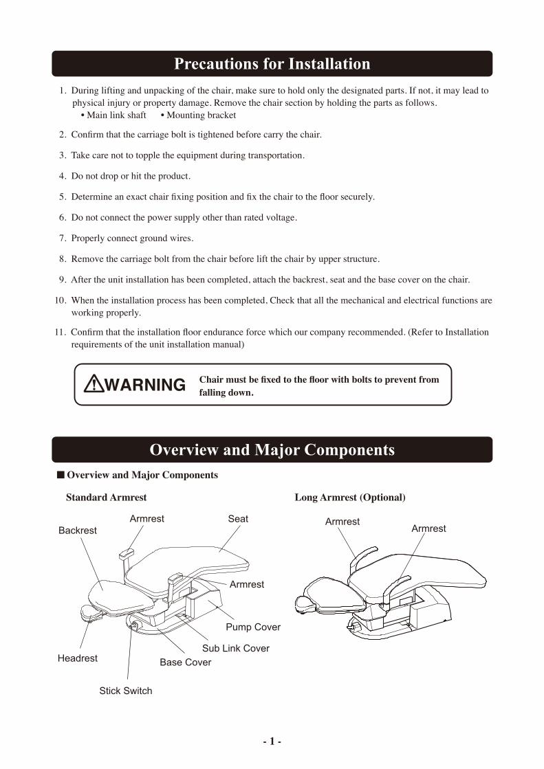
Overview and Major Components
Chair must be fixed to the floor with bolts to prevent from falling down.
ArmrestBackrest
Headrest
Stick Switch
Base Cover
Sub Link Cover
Pump Cover
Seat
Armrest
ArmrestArmrest
- 1 -
Precautions for Installation
Overview and Major Components
Standard Armrest Long Armrest (Optional)
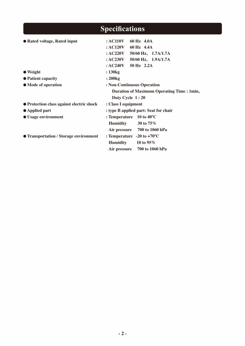
Specifications
Rated voltage, Rated input : AC110V 60 Hz 4.0A : AC120V 60 Hz 4.4A : AC220V 50/60 Hz, 1.7A/1.7A : AC230V 50/60 Hz, 1.9A/1.7A : AC240V 50 Hz 2.2A
Weight : 130kg Patient capacity : 200kg Mode of operation : Non-Continuous Operation
Duration of Maximum Operating Time : 1min, Duty Cycle 1 : 20
Protection class against electric shock : Class I equipment Applied part : type B applied part: Seat for chair Usage environment : Temperature 10 to 40ºC
Humidity 30 to 75% Air pressure 700 to 1060 hPa
Transportation / Storage environment : Temperature -20 to +70ºC Humidity 10 to 95% Air pressure 700 to 1060 hPa
- 2 -
Specifications
- 3 -
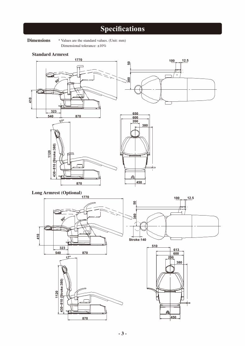
Dimensions
650
870
1120
430~
810 (
Str
oke:3
80)
450
60020017°
870540
90°
1770
410
323
50 100 12.5
38
0380
870
1120
430~
810 (
Str
oke:3
80
)
17°870540
90°
1770
410
323
50
100 12.5
38
0
Stroke:140
613
450
600200
380
510
* Values are the standard values. (Unit: mm) Dimensional tolerance: ±10%
Long Armrest (Optional)
Standard Armrest
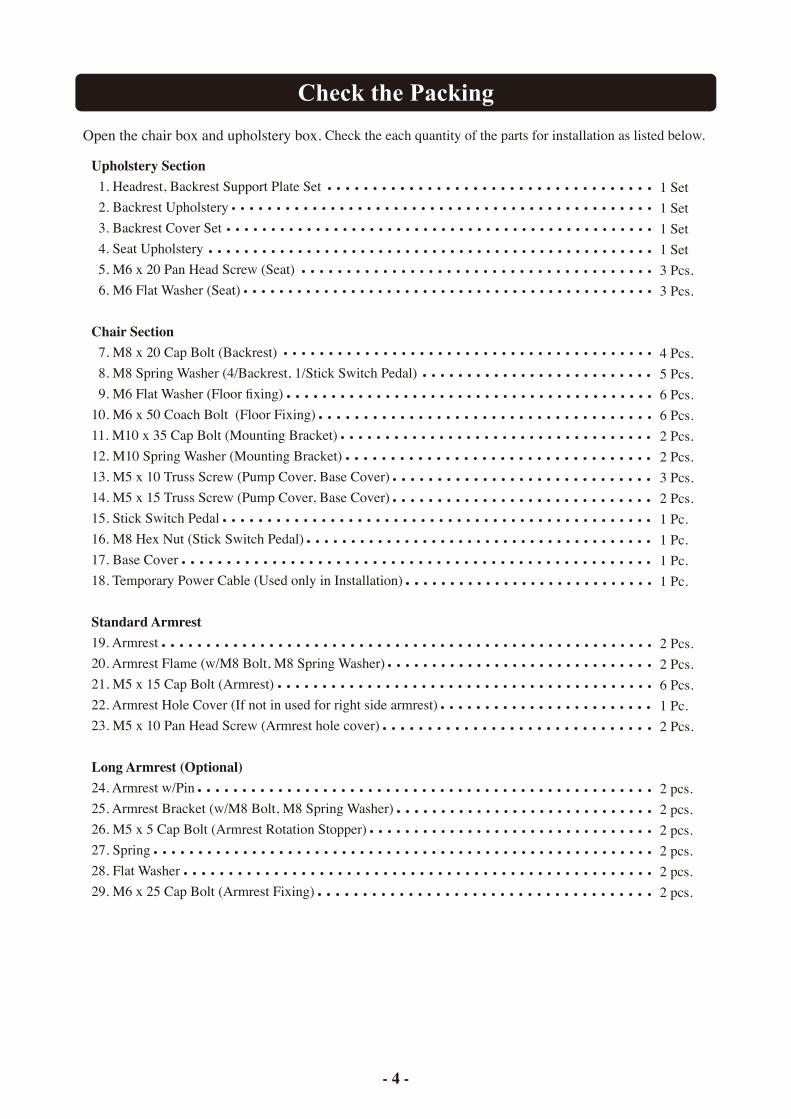
Open the chair box and upholstery box. Check the each quantity of the parts for installation as listed below.
- 4 -
Upholstery Section 1. Headrest, Backrest Support Plate Set 2. Backrest Upholstery 3. Backrest Cover Set 4. Seat Upholstery 5. M6 x 20 Pan Head Screw (Seat) 6. M6 Flat Washer (Seat)
Chair Section 7. M8 x 20 Cap Bolt (Backrest) 8. M8 Spring Washer (4/Backrest, 1/Stick Switch Pedal) 9. M6 Flat Washer (Floor fixing) 10. M6 x 50 Coach Bolt (Floor Fixing) 11. M10 x 35 Cap Bolt (Mounting Bracket) 12. M10 Spring Washer (Mounting Bracket) 13. M5 x 10 Truss Screw (Pump Cover, Base Cover) 14. M5 x 15 Truss Screw (Pump Cover, Base Cover) 15. Stick Switch Pedal 16. M8 Hex Nut (Stick Switch Pedal) 17. Base Cover 18. Temporary Power Cable (Used only in Installation)
Standard Armrest19. Armrest 20. Armrest Flame (w/M8 Bolt, M8 Spring Washer) 21. M5 x 15 Cap Bolt (Armrest) 22. Armrest Hole Cover (If not in used for right side armrest) 23. M5 x 10 Pan Head Screw (Armrest hole cover)
Long Armrest (Optional)24. Armrest w/Pin 25. Armrest Bracket (w/M8 Bolt, M8 Spring Washer) 26. M5 x 5 Cap Bolt (Armrest Rotation Stopper) 27. Spring 28. Flat Washer 29. M6 x 25 Cap Bolt (Armrest Fixing)
1 Set1 Set1 Set1 Set3 Pcs.3 Pcs.
4 Pcs.5 Pcs.6 Pcs.6 Pcs.2 Pcs.2 Pcs.3 Pcs.2 Pcs.1 Pc.1 Pc.1 Pc.1 Pc.
2 Pcs.2 Pcs.6 Pcs.1 Pc.2 Pcs.
2 pcs.2 pcs.2 pcs.2 pcs.2 pcs.2 pcs.
Check the Packing
Installation Instructions
Carton Box
Pallet Seat Frame
Pump Cover
Base Cover
Accessory Case
Main Link Shaft
Mounting BracketCarriage Bolt
M6 x 50 Coach Bolt
M6 x 50 Coach Bolt
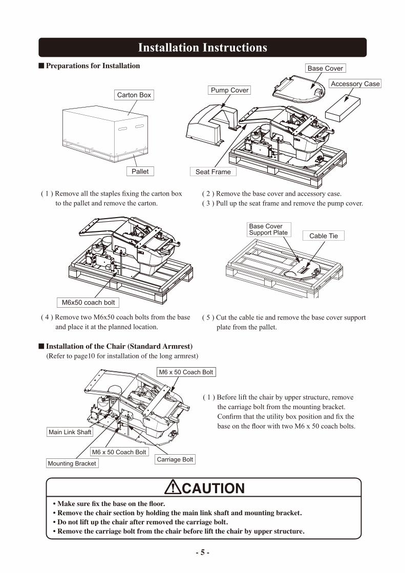
Preparations for Installation
( 1 ) Remove all the staples fixing the carton box to the pallet and remove the carton.
( 2 ) Remove the base cover and accessory case. ( 3 ) Pull up the seat frame and remove the pump cover.
Installation of the Chair (Standard Armrest) (Refer to page10 for installation of the long armrest)
( 1 ) Before lift the chair by upper structure, remove the carriage bolt from the mounting bracket. Confirm that the utility box position and fix the base on the floor with two M6 x 50 coach bolts.
• Make sure fix the base on the floor.• Remove the chair section by holding the main link shaft and mounting bracket.• Do not lift up the chair after removed the carriage bolt.• Remove the carriage bolt from the chair before lift the chair by upper structure.
- 5 -
M6x50 coach bolt
( 4 ) Remove two M6x50 coach bolts from the base and place it at the planned location.
Cable Tie
Base CoverSupport Plate
( 5 ) Cut the cable tie and remove the base cover support plate from the pallet.
Installation Instructions
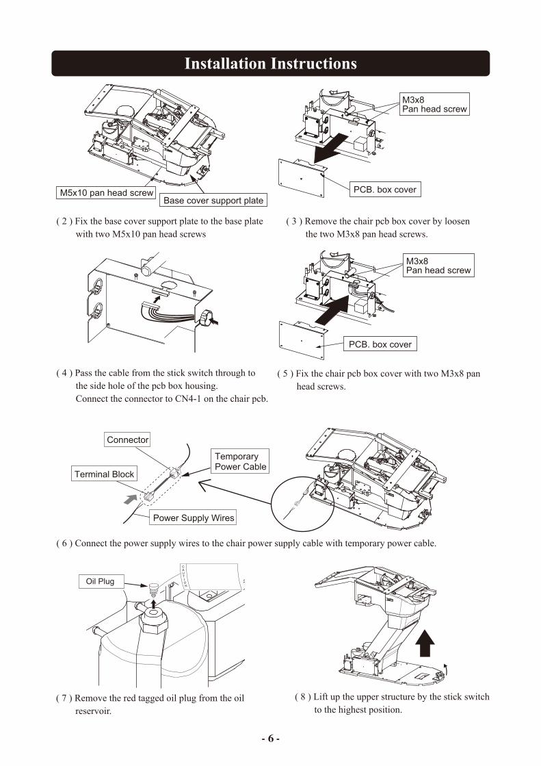
( 8 ) Lift up the upper structure by the stick switch to the highest position.
- 6 -
PCB. box cover
M3x8 Pan head screw
( 3 ) Remove the chair pcb box cover by loosen the two M3x8 pan head screws.
( 4 ) Pass the cable from the stick switch through to the side hole of the pcb box housing. Connect the connector to CN4-1 on the chair pcb.
M5x10 pan head screwBase cover support plate
( 5 ) Fix the chair pcb box cover with two M3x8 pan head screws.
Oil Plug
( 7 ) Remove the red tagged oil plug from the oil reservoir.
Temporary Power Cable
Power Supply Wires
Terminal Block
Connector
( 6 ) Connect the power supply wires to the chair power supply cable with temporary power cable.
( 2 ) Fix the base cover support plate to the base plate with two M5x10 pan head screws
PCB. box cover
M3x8 Pan head screw

Installation Instructions
M10 x 35 Cap Bolt
M10 Spring Washer
- 7 -
( 14 ) Fix the mounting bracket to the chair with four M10 spring washers and four M10 x 35 cap bolts as shown on above.
M6 x 50 Coach BoltM6 x 50 Coach Bolt
M6 Flat Washer
Flange CoverM5 x 10 Truss Screw
M4 x 12 Truss Screw
Armrest
M5 x 15 Cap Bolt
Armrest Frame
M8 Spring Washer
M8 x 20 Cap Bolt
M5 x 10 Pan Head Screw
Armrest Hole Cover
Mounting Bracket
M10 x 35 Cap Bolt
M10 Spring Washer
( 9 ) Fix the base on the floor with six M6 x 50 coach bolts.
The mounting bracket is heavy, be careful notto drop the mounting bracket when removing from the chair.
( 10 ) Remove the flange cover by removing the five truss screws.
( 11 ) Fix the armrest to armrest frame with three M5 x 15 cap bolts. (Refer to page10 for installation of the long armrest)
( 12 ) Fix the armrest to the chair • For both sides : Remove the two M8 x 20 cap screws and M8 spring washers from the armrest frame. Fix the both armrests to the chair with same screws and spring washers. • For one side : Remove the two M8 x 20 cap screws and M8 spring washers from the armrest frame. Fix the armrest to the chair with same screws and spring washers. Fix the armrest hole cover to other side with M5 x 10 pan head screws .
( 13 ) Remove the mounting bracket from the chair by removing two M10 x 35 cap bolts.

Backrest Support
M5 x 15 Pan Head Screw
Backrest
M8 x 20 Cap Bolt
M8 Spring Washer
Backrest Support Plate
Backrest Support
Backrest Support Plate
BackrestM5 x 15Pan Head Screw
M5 x 22Pan Head Screw
1
M5 Nut2
( 15 ) Move the chair backrest to forward position by stick switch.
( 16 ) Fix the backrest support plate to the backrest support by four M8 x 20 cap bolts with M8 spring washers.
( 19 ) Fix the backrest to the backrest support plate by four M5 x 15 pan head screws.
Installation Instructions
( 18 ) Unscrew the four M5 x 15 pan head screws and remove the backrest.
Befor doing the following steps
( 17 ) Confirm the headrest movement If the headrest vertical movement is too heavy or too light. Loosen the 2 M5 nut and adjust the 1 M5 x 22 pan head screws. Make sure that the nut is tightened after adjusted.
Install the unit according to the installation manual of the unit. After the unit installation has been completed, attach the backrest, seat and base cover to the chair.
- 8 -
Installation Instructions
Flange Cover
M5 x 10 Truss Screw
M4 x 12 Truss Screw
Flange Cover
Sub Link Cover
M6 Flat Washer
M6 x 20Pan Head Screw
Pump Cover
M5 x 15 Truss Screw M5 x 10 Truss Screw
M5 x 10 Truss Screw
Base Cover
M8 Nut
M8 Spring Washer
Stick Switch Pedal
Confirm that the chair is fixed to the floor securely before attach the covers.
- 9 -
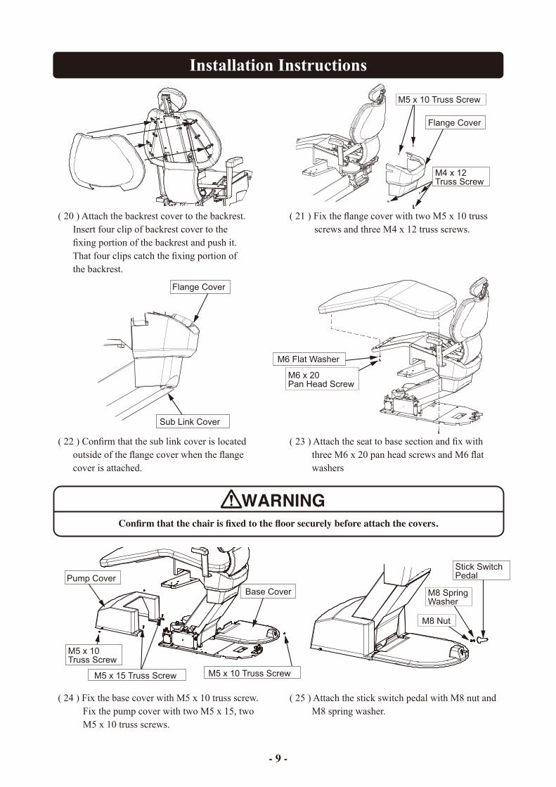
( 20 ) Attach the backrest cover to the backrest. Insert four clip of backrest cover to the fixing portion of the backrest and push it. That four clips catch the fixing portion of the backrest.
( 21 ) Fix the flange cover with two M5 x 10 truss screws and three M4 x 12 truss screws.
( 22 ) Confirm that the sub link cover is located outside of the flange cover when the flange cover is attached.
( 23 ) Attach the seat to base section and fix with three M6 x 20 pan head screws and M6 flat washers
( 24 ) Fix the base cover with M5 x 10 truss screw. Fix the pump cover with two M5 x 15, two M5 x 10 truss screws.
( 25 ) Attach the stick switch pedal with M8 nut and M8 spring washer.
- 10 -
Installation Instructions
Armrest Bracket
Armrest Bracket
Right Side Armrest Bracket
Armrest Bracket
Left Side Armrest Bracket
Armrest
Left Side Armrest Bracket
Right Side Armrest Bracket
Spring
Spring
Flat Washer
Flat Washer
M6 x 25 Cap Bolt
M6 x 25 Cap Bolt
Rotation Stopper Screw Fixing Positionfor Right Side Armrest
Rotation Stopper Screw Fixing Positionfor Left Side Armrest
M5 x 5 Rotation Stopper Screw
M5 x 5 Rotation Stopper Screw
M8 Spring Washer
M8 x 30 Cap Bolt
M8 x 30 Cap Bolt
M8 Spring Washer
Left Side Armrest
Right Side Armrest
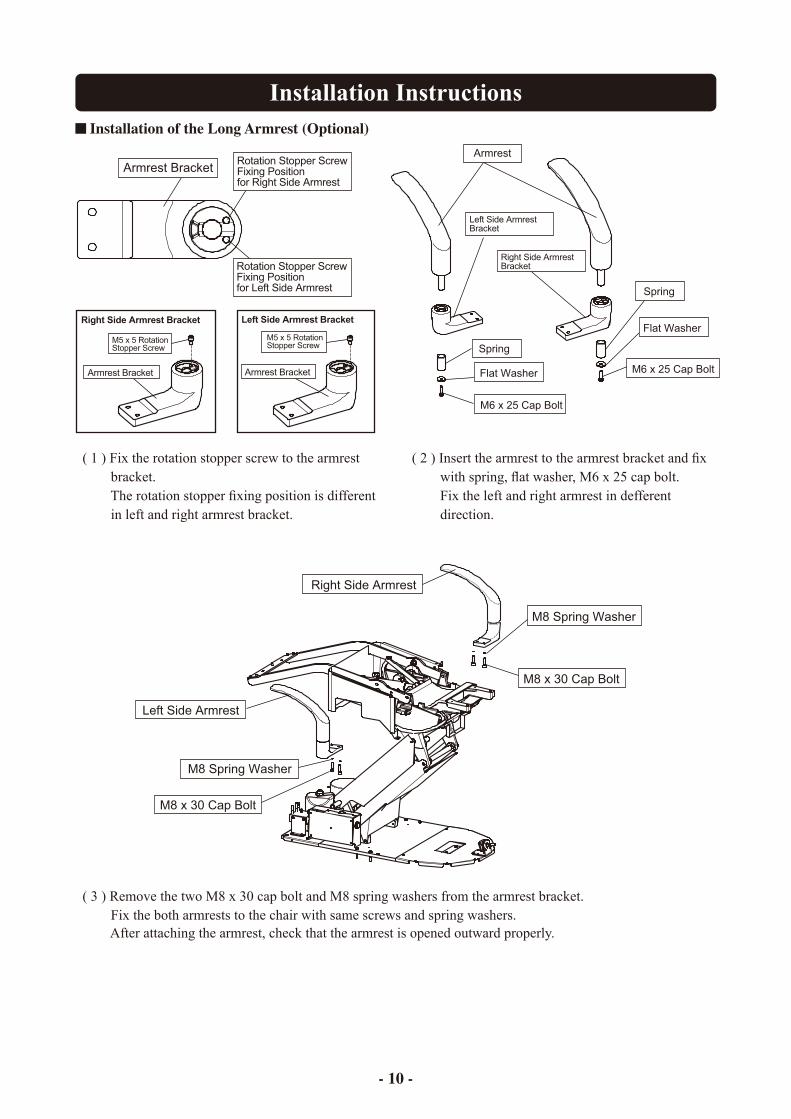
( 1 ) Fix the rotation stopper screw to the armrest bracket. The rotation stopper fixing position is different in left and right armrest bracket.
( 2 ) Insert the armrest to the armrest bracket and fix with spring, flat washer, M6 x 25 cap bolt. Fix the left and right armrest in defferent direction.
( 3 ) Remove the two M8 x 30 cap bolt and M8 spring washers from the armrest bracket. Fix the both armrests to the chair with same screws and spring washers. After attaching the armrest, check that the armrest is opened outward properly.
Installation of the Long Armrest (Optional)
Installation Instructions
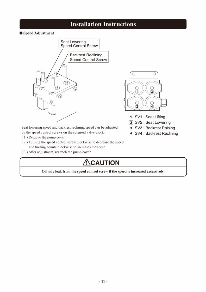
Seat LoweringSpeed Control Screw
Backrest RecliningSpeed Control Screw
SV1 : Seat LiftingSV2 : Seat LoweringSV3 : Backrest RaisingSV4 : Backrest Reclining
1
2
3
4
1
2
3
4
Oil may leak from the speed control screw if the speed is increased excessively.
- 11 -
Speed Adjustment
Seat lowering speed and backrest reclining speed can be adjustedby the speed control screws on the solenoid valve block.( 1 ) Remove the pump cover.( 2 ) Turning the speed control screw clockwise to decrease the speed and turning counterclockwise to increases the speed.( 3 ) After adjustment, reattach the pump cover.
Installation Instructions
SV
1S
V3
SV
2S
V4
Bac
kres
t C
ylin
der
Sea
t E
leva
tio
n C
ylin
der
Mo
tor
Pu
mp
So
len
oid
Val
ve B
lock
Oil
Res
ervo
ir
TS
M-C
BC
-5LP
-*
Fla
t Sho
ckle
ssF
lat S
hock
less
Nee
dle
Sho
ckle
ssN
eedl
e S
hock
less
Flow
Con
trol
Flow
Con
trol
- 12 -
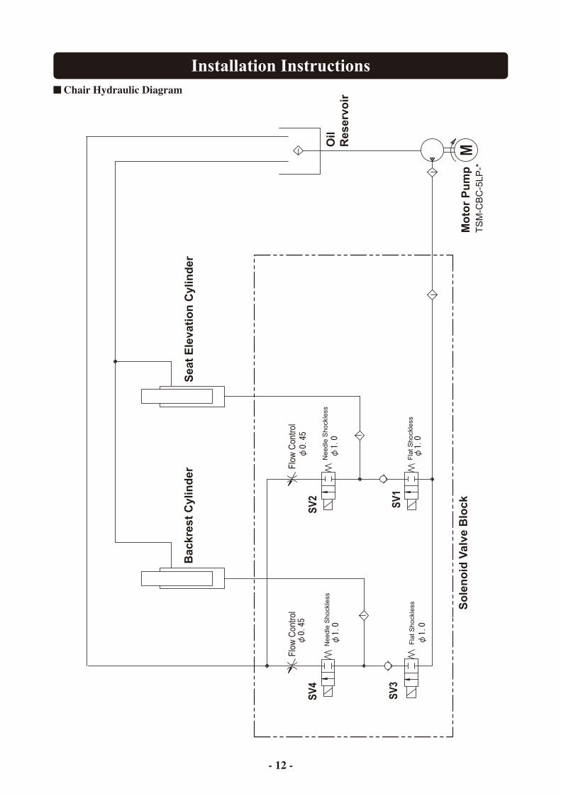
Chair Hydraulic Diagram

Installation Instructions
Bro
wn
Bro
wn
Bro
wn
Bro
wn
Bro
wn
Bro
wn
Bro
wn
Bro
wn
Blu
e
4G
reen
/Yel
low
VL4
P
1 2 3
Trun
k lin
e fo
r stic
k sw
itch
1A0C
9N**
Stic
k S
witc
h P
CB
.(1
G01
Q1*
*)
COM
54
32
1
XH
10P
CN
4-2
Black
YellowOrangeRedBrown
109
78
65
12
43
321
The
side
with
bla
ck d
ot
has
mal
e pi
nsC
ap
Plu
g2
1
M
Cap
acito
r45
µF
Dow
n
Forw
ard
Bac
kwar
d
Up
SV
4
SV
3
SV
2
SV
1
Pot
entio
met
er fo
r Up/
Dow
n
Pot
entio
met
er fo
r Bac
kres
tR
VQ
24Y
N05
20S
B50
2(1
40°5
KΩ
)
Ora
nge
Red
Red
3211 2 3
12
All prohibition
Down prohibition
All prohibition
Down prohibition
CN
18-2
XH
4PX
H4P
CN
18-1
43
21
43
DC
5VIn
put
GN
D
XH
3P
12B
row
n1 2 3
CN
12
1 5 6 3 7 4 82
VH
4PC
N3
1 2 3 4
Red
Whi
teY
ello
w
CN
13
321
Ora
nge
Bro
wn
13
XH
3P
VH
3P
1 2 3
CN
2
Blu
e
Bro
wn
AC
110V
/60H
z
CN
5m
olex
NM
F8P
Up
Dow
n
Cha
ir C
ontr
ol P
CB
M2_
PLA
TFO
RM
T4N
V(1
G04
FZ**
)
GN
DIn
put
DC
5V
MO
DE
Pre
ss a
nd h
old
Mod
e S
W: I
nitia
l Set
ting
LED
1Y
ello
wO
NP
ower
On
ON
ON
Lim
it M
ode
Nor
mal
Mod
e
110V 0V
13V
0V
JP1
100V
110V
120V
LED
8LE
D11
Red
Gre
enO
NO
FFP
rohi
bitio
n LE
D (L
ED
OFF
: w
hen
proh
ibite
d al
l mov
emen
t) / (
Nor
mal
: O
N)
Con
nect
or S
ymbo
l
RV
Q24
YN
05 2
0S B
502
(140
°5K
Ω)
1A0C
8Y**
Pot
entio
met
er fo
r Bac
kres
t Sec
tion
Pot
entio
met
er fo
r Up/
Dow
n S
ectio
n1A
0C8U
**
1A0C
8Q**
1A0C
9F**
Trun
k lin
e fo
r Mot
or/C
apac
itor
1G03
U7*
*
Mot
or A
ssy(
110-
120V
)M
otor
/
Cap
acito
r
VL3
P
STO
RE
LIM
NO
L
Red
Whi
te/B
row
n
Yel
low
1G04
2N**
Sol
enoi
d V
alve
Ass
y(11
0V/6
0Hz)
*Wire
Col
or :
Bro
wn
Gre
en/Y
ello
w
TSM
-CB
C-5
LP-M
1-E
Mot
or
SM
2P1 2
OrangeYellow
1A0C
8S**
Trun
k lin
e fo
r cha
ir lo
ck
34
21
56
87
910
XM
9P91 2 3 4 5 6 87
BrownRedOrangeYellowGreenBluePurpleGray
Black
1A0C
8T**
Trun
k lin
e fo
r ope
ratio
n sw
itch
(Uni
t)
CN
4-1
XH
10P
CO
MN
.O.
RedBrown
N.O
.C
OM
Cha
ir Lo
ck S
witc
h S
ectio
n1A
0C9G
**
Bro
wn
Brown
Red
UpDown
P0P1P2LP
N.C.COM
COMN.C.LPP2P1P0
DownUp
To tr
unk
line
from
util
ity b
ox
To tr
unk
line
from
util
ity b
ox
To tr
unk
line
from
util
ity b
ox
Forw
ard
Bac
kwar
d
ForwardBackward
UpDownRightLeft
ForwardBackward
Trun
k lin
e fo
r pow
er (C
hair
PC
B.)
PC
B id
entif
icat
ion
num
ber :
M2_
PLA
TFO
RM
-CN
00M
icro
com
pute
r : u
PD
78F0
535A
GK
-GA
J-A
XP
rogr
am n
umbe
r : T
B10
00**
110V
/60H
z
Chair Electrical Diagram (110V 60Hz)
- 13 -
Installation Instructions
Whi
teW
hite
Whi
teW
hite
Whi
teW
hite
Whi
te
Bro
wn
Blu
e
4G
reen
/Yel
low
VL4
P
1 2 3
Trun
k lin
e fo
r stic
k sw
itch
1A0C
9N**
Stic
k S
witc
h P
CB
.(1
G01
Q1*
*)
54
32
1
XH
10P
CN
4-2
Black
YellowOrangeRedBrown
109
78
65
12
43
321
The
side
with
bla
ck d
ot
has
mal
e pi
nsC
ap
Plu
g2
1
M
Cap
acito
r45
µF
Dow
n
Up
SV
4
SV
3
SV
2
SV
1
Pot
entio
met
er fo
r Up/
Dow
n
Pot
entio
met
er fo
r Bac
kres
tR
VQ
24Y
N05
20S
B50
2(1
40°5
KΩ
)
Ora
nge
Red
Red
3211 2 3
12
[Mot
or/C
apac
itor]
All prohibition
Down prohibition
All prohibition
Down prohibition
CN
18-2
XH
4P
[Pro
hibi
tion
Inpu
t]
XH
4PC
N18
-1
43
21
43
[Up/
Dow
n V
R In
put]
DC
5VIn
put
GN
D
XH
3P
12B
row
n1 2 3
CN
12
1 5 6 3 7 4 82
VH
4PC
N3
1 2 3 4
Red
Whi
te
Yel
low
CN
13
321
Ora
nge
Bro
wn
13
XH
3P
VH
3P
1 2 3
CN
2
Blu
e
Bro
wn
AC
120V
/60H
z
Mot
or/
Cap
acito
r CN
5m
olex
NM
F8P
[SV
Inpu
t]
Up
Dow
n
[Pow
er In
put]
Cha
ir C
ontr
ol P
CB
M2_
PLA
TFO
RM
T4V
N(1
G04
FZ**
)
[Sw
itch
Inpu
t]
GN
DIn
put
DC
5V
[Bac
kres
t VR
Inpu
t]
MO
DE
Pre
ss a
nd h
old
Mod
e S
W: I
nitia
l Set
ting
LED
1Y
ello
wO
NP
ower
On
ON
ON
Lim
it M
ode
Nor
mal
Mod
e
120V 0V
13V
0V
JP1
100V
110V
120V
LED
8LE
D11
Red
Gre
enO
NO
FF
Pro
hibi
tion
LED
(LE
D O
FF :
whe
n pr
ohib
ited
all m
ovem
ent)
/ (N
orm
al :
ON
)
Con
nect
or S
ymbo
l
RV
Q24
YN
05 2
0S B
502
(140
°5K
Ω)
1A0C
8Y**
Pot
entio
met
er fo
r Bac
kres
t Sec
tion
Pot
entio
met
er fo
r Up/
Dow
n S
ectio
n1A
0C8U
**
1A0C
8Q**
1A0C
9F**
Trun
k lin
e fo
r Mot
or/C
apac
itor
1G03
U7*
*M
otor
Ass
y(11
0-12
0V)
VL3
P
STO
RE
LIM
NO
L
Red
Whi
te/B
row
n
Yel
low
1G04
2P**
Sol
enoi
d V
alve
Ass
y(12
0V/6
0Hz)
*Wire
Col
or :
Whi
te
Gre
en/Y
ello
w
TSM
-CB
C-5
LP-M
1-E
Mot
or
SM
2P1 2
OrangeYellow
1A0C
8S**
Trun
k lin
e fo
r cha
ir lo
ck
34
21
56
87
910
XM
9P91 2 3 4 5 6 87
BrownRedOrangeYellowGreenBluePurpleGray
Black
1A0C
8T**
Trun
k lin
e fo
r ope
ratio
n sw
itch
(Uni
t)
CN
4-1
XH
10P
CO
MN
.O.
RedBrown
N.O
.C
OM
Cha
ir Lo
ck S
witc
h S
ectio
n1A
0C9G
**
Whi
te
Brown
Red
UpDown
ForwardBackward
P0P1P2LP
N.C.COM
COMN.C.LPP2P1P0
DownUp
To tr
unk
line
from
util
ity b
ox
To tr
unk
line
from
util
ity b
ox
To tr
unk
line
from
util
ity b
ox
Forw
ard
Bac
kwar
d
Forw
ard
Bac
kwar
d
ForwardBackward
PC
B id
entif
icat
ion
num
ber :
M2_
PLA
TFO
RM
-CN
00M
icro
com
pute
r : u
PD
78F0
535A
GK
-GA
J-A
XP
rogr
am n
umbe
r : T
B10
00**
Trun
k lin
e fo
r pow
er (C
hair
PC
B.)
COM
UpDownRightLeft
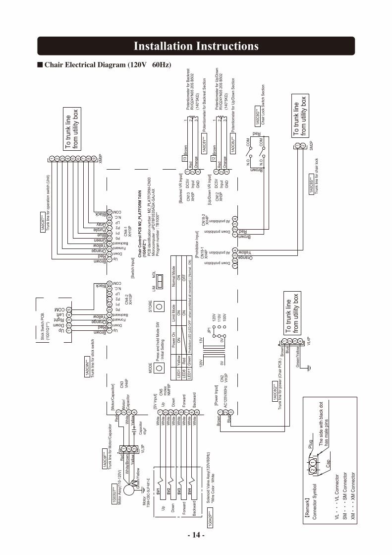
Chair Electrical Diagram (120V 60Hz)
- 14 -
Installation Instructions
Gre
enG
reen
Gre
enG
reen
Gre
enG
reen
Gre
en
UpDown
P0P1P2LP
N.C.COM
COMN.C.LPP2P1P0
DownUp
Red
Brown
Gre
en
1A0C
9G**
Cha
ir Lo
ck S
witc
h S
ectio
n
CO
MN
.O.
BrownRed
N.O
.C
OM
XH
10P
CN
4-1
Trun
k lin
e fo
r ope
ratio
n sw
itch
(Uni
t)1A
0C8T
**
Black
GrayPurpleBlueGreenYellowOrangeRedBrown
7 8654321 9
XM
9P
109
78
65
12
43
Trun
k lin
e fo
r cha
ir lo
ck1A
0C8S
**
YellowOrange
21
SM
2P
Mot
orTS
M-C
BC
-5LP
-M2-
E
Gre
en/Y
ello
w
Sol
enoi
d V
alve
Ass
y(22
0V)
*Wire
Col
or :
Gre
en1G
03U
5**
Yel
low
Whi
te/B
row
n
Red
NO
LLI
MS
TOR
E
VL3
P
Mot
or A
ssy(
220-
240V
)1G
03U
8**
Trun
k lin
e fo
r Mot
or/C
apac
itor
1A0C
9F**
1A0C
8Q**
1A0C
8U**
Pot
entio
met
er fo
r Up/
Dow
n S
ectio
n
Pot
entio
met
er fo
r Bac
kres
t Sec
tion
1A0C
8Y**
RV
Q24
YN
05 2
0S B
502
(140
°5K
Ω)
Con
nect
o r S
ymbo
l
Pro
hibi
tion
LED
(LE
D O
FF :
whe
n pr
ohib
ited
all m
ovem
ent)
/ (N
orm
al :
ON
)
OFF
ON
Gre
enR
edLE
D11
LED
8
240V
230V
220V
JP1
0V13V
0V
220V
Nor
mal
Mod
eLi
mit
Mod
eO
NO
NP
ower
On
ON
Yel
low
LED
1
Pre
ss a
nd h
old
Mod
e S
W: I
nitia
l Set
ting
MO
DE
DC
5VIn
put
GN
D
Cha
ir C
ontr
ol P
CB
M3_
PLA
TFO
RM
T4V
N(1
G04
G0*
*)
Dow
n
Up
mol
exN
MF8
P
CN
5
Mot
or/
Cap
acito
r
AC
220V
Bro
wn
Blu
e
CN
2
321
VH
3P
XH
3P
13B
row
n
Ora
nge
1 2 3
CN
13
Yel
low
Whi
te
Red
4321C
N3
VH
4P
2 8473651
CN
12
321B
row
n12
XH
3P
GN
DIn
put
DC
5V
34
12
34
CN
18-1
XH
4PX
H4P
CN
18-2
Down prohibition
All prohibition
Down prohibition
All prohibition
21
321 1 2 3
Red
Red
Ora
nge
RV
Q24
YN
05 2
0S B
502
(140
°5K
Ω)
Pot
entio
met
er fo
r Bac
kres
t
Pot
entio
met
er fo
r Up/
Dow
n
SV
1
SV
2
SV
3
SV
4
Up
Dow
n
Cap
acito
r14
µF
M
12
Plu
g
Cap
The
side
with
bla
ck d
ot
has
mal
e pi
ns
1 2 3
34
21
56
87
910
BrownRedOrangeYellow
Black
CN
4-2
XH
10P
12
34
5
Stic
k S
witc
h P
CB
.(1
G01
Q1*
*)
1A0C
9N**
Trun
k lin
e fo
r stic
k sw
itch 321
VL4
P
Gre
en/Y
ello
w4
Blu
eB
row
n
To tr
unk
line
from
util
ity b
ox
To tr
unk
line
from
util
ity b
ox
To tr
unk
line
from
util
ity b
ox
Forw
ard
Bac
kwar
d
COM
UpDownRightLeft
Trun
k lin
e fo
r pow
er (C
hair
PC
B.)
PC
B id
entif
icat
ion
num
ber :
M3_
PLA
TFO
RM
-CN
00M
icro
com
pute
r : u
PD
78F0
535A
GK
-GA
J-A
XP
rogr
am n
umbe
r : T
B10
00**
Forw
ard
Bac
kwar
d
ForwardBackward
ForwardBackward
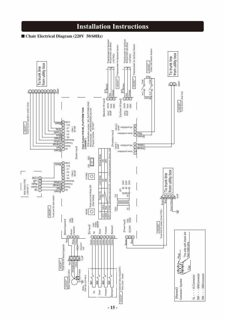
Chair Electrical Diagram (220V 50/60Hz)
- 15 -

Installation Instructions
UpDown
P0P1P2LP
N.C.COM
COMN.C.LPP2P1P0
DownUp
Red
Brown
Gra
yG
ray
Gra
yG
ray
Gra
yG
ray
Gra
y
1A0C
9G**
Cha
ir Lo
ck S
witc
h S
ectio
n
CO
MN
.O.
BrownRed
N.O
.C
OM
XH
10P
CN
4-1
Trun
k lin
e fo
r ope
ratio
n sw
itch
(Uni
t)1A
0C8T
**
Black
GrayPurpleBlueGreenYellowOrangeRedBrown
7 8654321 9
XM
9P
109
78
65
12
43
Trun
k lin
e fo
r cha
ir lo
ck1A
0C8S
**
YellowOrange
21
SM
2P
Mot
orTS
M-C
BC
-5LP
-M2-
E
Gre
en/Y
ello
w
Sol
enoi
d V
alve
Ass
y(23
0V/2
40V
)*W
ire C
olor
: G
ray
1G03
U6*
*
Yel
low
Whi
te/B
row
nR
ed
NO
LLI
MS
TOR
E
Sho
rt-ci
rcui
t acc
ordi
ng to
the
pow
er-s
uppl
y vo
ltage
VL3
P
Mot
or A
ssy(
220-
240V
)1G
03U
8**
Trun
k lin
e fo
r Mot
or/C
apac
itor
1A0C
9F**
1A0C
8Q**
1A0C
8U**
Pot
entio
met
er fo
r Up/
Dow
n S
ectio
n
Pot
entio
met
er fo
r Bac
kres
t Sec
tion
1A0C
8Y**
RV
Q24
YN
05 2
0S B
502
(140
°5K
Ω)
Con
nect
or S
ymbo
l
Pro
hibi
tion
LED
(LE
D O
FF :
whe
n pr
ohib
ited
all m
ovem
ent)
/ (N
orm
al :
ON
)
OFF
ON
Gre
enR
edLE
D11
LED
8
240V
230V
220V
JP1
0V13V
0V
230/
240V
Nor
mal
Mod
eLi
mit
Mod
eO
NO
NP
ower
On
ON
Yel
low
LED
1
Pre
ss a
nd h
old
Mod
e S
W: I
nitia
l Set
ting
MO
DE
DC
5VIn
put
GN
D
Cha
ir C
ontr
ol P
CB
M3_
PLA
TFO
RM
T4V
N(1
G04
G0*
*)
Dow
n
Up
mol
exN
MF8
P
CN
5
Mot
or/
Cap
acito
r
AC
230/
240V
Bro
wn
Blu
e
CN
2
321
VH
3P
XH
3P
13B
row
n
Ora
nge
1 2 3
CN
13
Yel
low
Whi
te
Red
Gra
y
4321C
N3
VH
4P
2 8473651
CN
12
321B
row
n12
XH
3PG
ND
Inpu
tD
C5V
34
12
34
CN
18-1
XH
4PX
H4P
CN
18-2
Down prohibition
All prohibition
Down prohibition
All prohibition
21
321 1 2 3
Red
Red
Ora
nge
RV
Q24
YN
05 2
0S B
502
(140
°5K
Ω)
Pot
entio
met
er fo
r Bac
kres
t
Pot
entio
met
er fo
r Up/
Dow
n
SV
1
SV
2
SV
3
SV
4
Up
Dow
n
Cap
acito
r14
µF
M
12
Plu
g
Cap
The
side
with
bla
ck d
ot
has
mal
e pi
ns
1 2 3
34
21
56
87
910
BrownRedOrangeYellow
Black
CN
4-2
XH
10P
12
34
5
Stic
k S
witc
h P
CB
.(1
G01
Q1*
*)
1A0C
9N**
Trun
k lin
e fo
r stic
k sw
itch 321
VL4
P
Gre
en/Y
ello
w4
Blu
eB
row
n
To tr
unk
line
from
util
ity b
ox
To tr
unk
line
from
util
ity b
ox
To tr
unk
line
from
util
ity b
ox
Forw
ard
Bac
kwar
d
COM
UpDownRightLeft
ForwardBackward
ForwardBackward
Trun
k lin
e fo
r pow
er (C
hair
PC
B.)
PC
B id
entif
icat
ion
num
ber :
M3_
PLA
TFO
RM
-CN
00M
icro
com
pute
r : u
PD
78F0
535A
GK
-GA
J-A
XP
rogr
am n
umbe
r : T
B10
00**
Forw
ard
Bac
kwar
d
230V
50/
60 :
240
V 5
0Hz
Chair Electrical Diagram (230V 50/60Hz • 240V 50Hz)
- 16 -

BOOK NO. 1E03Q2C0Printed in Vietnam 2014-06
2-1-1, Higashishinsaibashi,Chuo-ku,Osaka, 542-0083,JapanTEL : +81-6-6213-5945 / FAX : +81-6-6212-3680www.takara-net.co
TAKARA BELMONT CORPORATION
BELMONT MANUFACTURING CO., LTD. (Manufacturer) Long Duc Industrial Park, Long Thanh District, Dong Nai Province, Viet NamTEL : +84-613-201-100 / FAX : +84-613-201-096