Installation Instructions :BMW E39 M5 : Page 1 · 2018-12-11 · Installation Instructions :BMW E39...
11
Installation Instructions :BMW E39 M5 : Page 1 1. We will start by removing the front bumper. Remove the 3 x 8mm hex head bolts in the wheel arch liners on both sides. Turn the wheels to gain access. 2. Remove 4 x 10mm hex head bolts from each wheel liner form the bottom of each bumper side. Once removed you should be able to remove the plastic under shields from the base of the bumper on both side. Once removed you can disconnect the fog lights. 3. Remove the 2 main Torx bolts which hold bumper in place. These are located behind the number plate area looking upwards from under the bumper. See photo. 4. Pull the bumper out from both sides – partially. (2 people are required, one on each side). Before fully removing the bumper, disconnect the PDC sensors and headlight washer hose. Once these are disconnected you can fully remove the bumper. 3 2
Transcript of Installation Instructions :BMW E39 M5 : Page 1 · 2018-12-11 · Installation Instructions :BMW E39...

Installation Instructions :BMW E39 M5 : Page 1
1. We will start by removing the front bumper. Remove the 3 x 8mm
hex head bolts in the wheel arch liners on both sides. Turn the
wheels to gain access.
2. Remove 4 x 10mm hex head bolts from each wheel liner form the bottom
of each bumper side. Once removed you should be able to remove the
plastic under shields from the base of the bumper on both side. Once
removed you can disconnect the fog lights.
3. Remove the 2 main Torx bolts which hold bumper in place. These are
located behind the number plate area looking upwards from under the
bumper. See photo.
4. Pull the bumper out from both sides – partially. (2 people are required,
one on each side). Before fully removing the bumper, disconnect the PDC
sensors and headlight washer hose. Once these are disconnected you can
fully remove the bumper.
3
2
Installation Instructions : BMW E39 M5 : Page 2
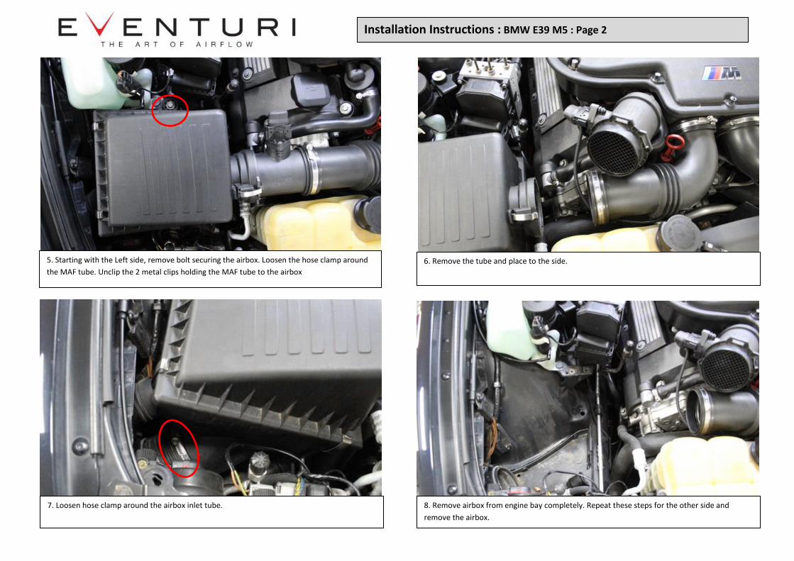
5. Starting with the Left side, remove bolt securing the airbox. Loosen the hose clamp around
the MAF tube. Unclip the 2 metal clips holding the MAF tube to the airbox
6. Remove the tube and place to the side.
7. Loosen hose clamp around the airbox inlet tube. 8. Remove airbox from engine bay completely. Repeat these steps for the other side and
remove the airbox.

9. Remove bolts securing inlet ducts in place on both sides.
11. We now need to remove the Foglamp surrounds. Start by pushing the clips down from
behind the bumper. This should allow you to push the surround out.
12. Remove the surrounds on both sides.
10. Remove the ducts completely on both sides.
Installation Instructions : BMW E39 M5: Page 3
Installation Instructions : BMW E39 M5: Page 4
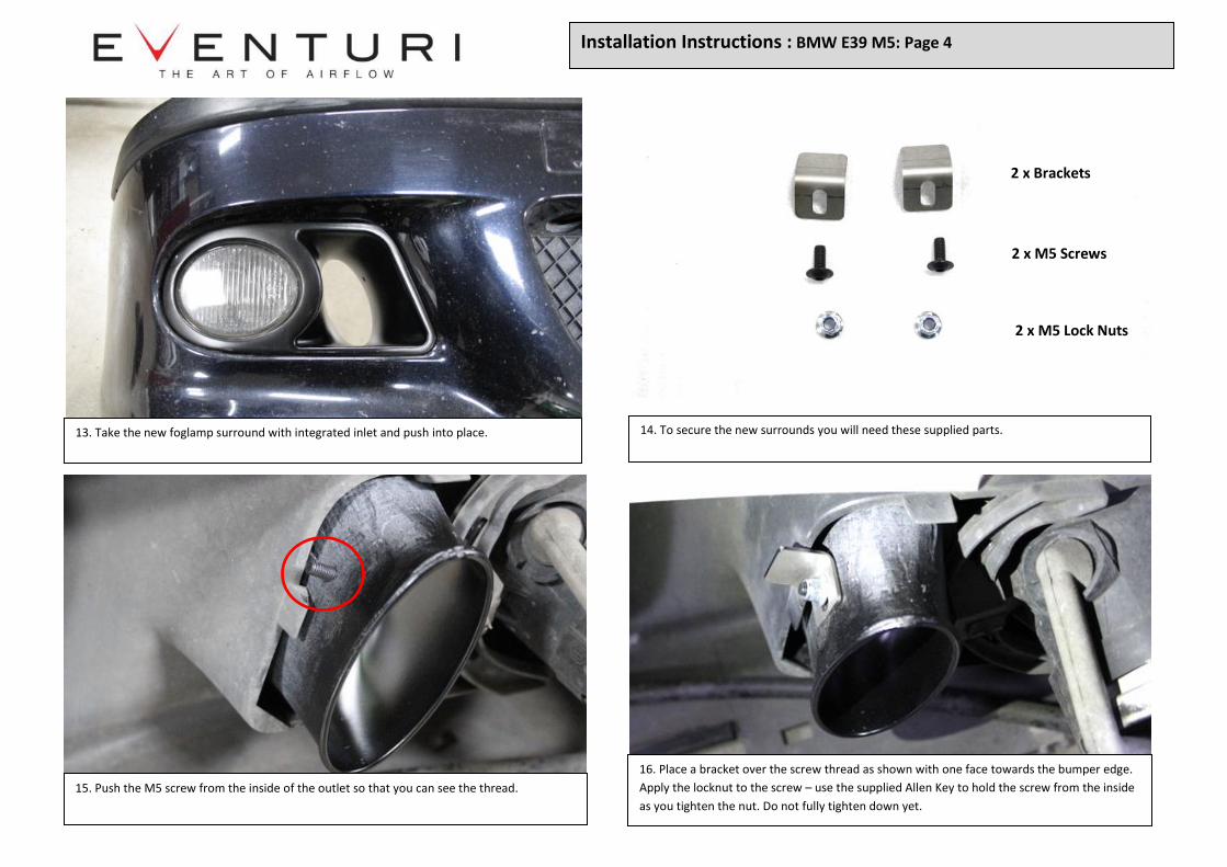
13. Take the new foglamp surround with integrated inlet and push into place.
.
14. To secure the new surrounds you will need these supplied parts.
15. Push the M5 screw from the inside of the outlet so that you can see the thread.
.
16. Place a bracket over the screw thread as shown with one face towards the bumper edge.
Apply the locknut to the screw – use the supplied Allen Key to hold the screw from the inside
as you tighten the nut. Do not fully tighten down yet.
.
2 x Brackets
2 x M5 Screws
2 x M5 Lock Nuts
Installation Instructions : BMW E39 M5: Page 5
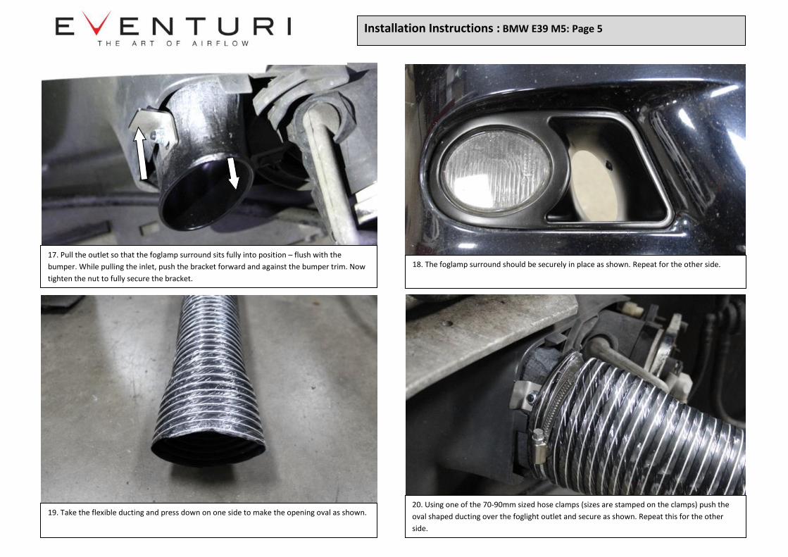
17. Pull the outlet so that the foglamp surround sits fully into position – flush with the
bumper. While pulling the inlet, push the bracket forward and against the bumper trim. Now
tighten the nut to fully secure the bracket.
.
18. The foglamp surround should be securely in place as shown. Repeat for the other side.
19. Take the flexible ducting and press down on one side to make the opening oval as shown.
.
20. Using one of the 70-90mm sized hose clamps (sizes are stamped on the clamps) push the
oval shaped ducting over the foglight outlet and secure as shown. Repeat this for the other
side.

Installation Instructions : BMW E39 M5: Page 6
21. Hold the bumper up against the car and reconnect the headlamp washer and PDC
sensors. Route the ducting on both side into the opening to the airboxes.
22. Pull the ducting through into the engine bay area as shown on both sides.
23. Push the bumper into place and secure with the 2 main Torx bolts as well as the liner
screws removed previously.
24. We will now fix the duct positioning inside the engine bay. To do that we need these
brackets and an M6 bolt with Nut for each bracket.

Installation Instructions : BMW E39 M5: Page 7
25. Starting with the Left side (as you look at the car from the front) The bracket will secure
to the mounting point shown here.
.
26. Fasten the bracket to the mount as shown using an M6 bolt and nut. The toothed end of the
bracket goes into the duct to position it so that it will face the filter. Shown in red for clarity. Do
for both sides.
27. Identify the LEFT and RIGHT side intakes.
28. Take the LEFT side intake and push a silicon tube onto the outlet as shown. Put 2 hose clamps
over the silicon. Clamps should both be 80-100mm size (size is stamped on the clamp). Tighten
the clamp around the carbon only.
LEFT SIDE RIGHT SIDE

Installation Instructions : BMW E39 M5: Page 8
29. Take 1 washer, 1 D-washer and 2 x M5 shallow nuts. 30. Starting with the Left side (LEFT side as you look at the car from the front) Remove the nut
holding this sensor in place just above the duct, on the wing.
2 x Shallow Nuts
Washer
D-Washer
31. Secure the sensor with 1 shallow nut. 32. Now place the D-Washer over the thread so the flat face is at the bottom as shown.

Installation Instructions : BMW E39 M5: Page 9
33. Loosen the clamp around the inlet manifold as shown and rotate the inlet tubing
upwards. Re-insert the MAF tube and tighten the MAF tube into place.
.
34. Push the LEFT side housing with silicon onto the MAF tube. Do not tighten yet.
35. Rotate the assembly down while pushing the intake back to get clearance with the wing. 36. The base of the heat shield should slot into place as shown. Photo is showing the rear of the
shield.
Loosen

Installation Instructions : BMW E39 M5: Page 10
37. As you move the intake down – push back the bracket on the front of the intake to clear
the wing. It needs to sit over the sensor – see next step.
.
38. Position the bracket so that it sits over the thread securing the sensor. Ensure that the D-
Washer over the sensor is still in correct orientation.
39. Use the remaining Washer and Shallow nut from step 29. Secure the bracket. 40. Ensure the silicon is sitting squarely on the MAF tube and tighten the hose clamp around the
silicon over the MAF tube.

41. Tighten the hose clamp around the inlet manifold which was loosened previously in
step 33. Check all hose clamps for tightness.
42. Repeat steps 28 to 41 for the RIGHT SIDE intake.
Installation Instructions : BMW E39 M5: Page 11
You have now completed the installation of the Eventuri BMW E39 M5 System.
Please take all necessary precautions while installing this system. Eventuri cannot
take responsibility for an incorrectly installed intake or any damage caused during
installation.