Installation Instructions and User GuideBS EN 1111:1999 (HP) thermostatic mixing valve standards. BS...
28
Please keep this booklet for future reference. Installer, when you have read these instructions please ensure you leave them with the user. Installation Instructions and User Guide Single & Dual Control Concealed Shower Valves Models covered: FLT CSHCVO C, FLT SQSHCAR C, FLT SQSHCDIV C, FLT SQSHCFH C, PM2 SQSHCVO C & PM2 CSHCVO C
Transcript of Installation Instructions and User GuideBS EN 1111:1999 (HP) thermostatic mixing valve standards. BS...

Please keep this booklet for future reference.
Installer, when you have read these instructions please ensure you leave them with the user.
Installation Instructions and User GuideSingle & Dual Control Concealed Shower Valves
Models covered: FLT CSHCVO C, FLT SQSHCAR C, FLT SQSHCDIV C, FLT SQSHCFH C, PM2 SQSHCVO C & PM2 CSHCVO C

2
Contents
Thank you for choosing Bristan, the UK’s leading showers and taps expert.
Your Bristan mixer tap is a thermostatic mixer incorporating a wax capsule thermostat to ensure constant temperatures. These instructions are for your guidance to a safe and successful installation and should be left with the user. All products manufactured and supplied by Bristan are safe providing they are installed correctly and receive regular maintenance in accordance with these instructions.
Important Safety Information ................................................... 3
General Information ................................................................. 4
Specifications ........................................................................... 5
Installation Requirements ....................................................... 6-9System Requirements ......................................................... 6-7WRAS IRN’s ......................................................................... 8TMV3 .................................................................................... 9
Prior to Installation .................................................................. 10Installation ................................................................................ 11-17
Shower Valve ........................................................................ 11-12Re-fit Control Handle .......................................................... 13Wall Outlet ............................................................................ 14Rigid Riser ............................................................................ 15Fixed Head ........................................................................... 16Adjustable Riser ................................................................... 17
Operating the Shower .............................................................. 18
Commissioning ......................................................................... 19
Maintenance ............................................................................. 20-23Cartridge Cleaning ............................................................. 20
Non-Return Valve Cleaning ................................................ 21
Adjusting the Temperature ................................................. 22-23
Troubleshooting ........................................................................ 24-25
Guarantee ................................................................................. 26-27
Need help? Give us a call on 0844 701 6273 and speak to one of our trained advisers.
3
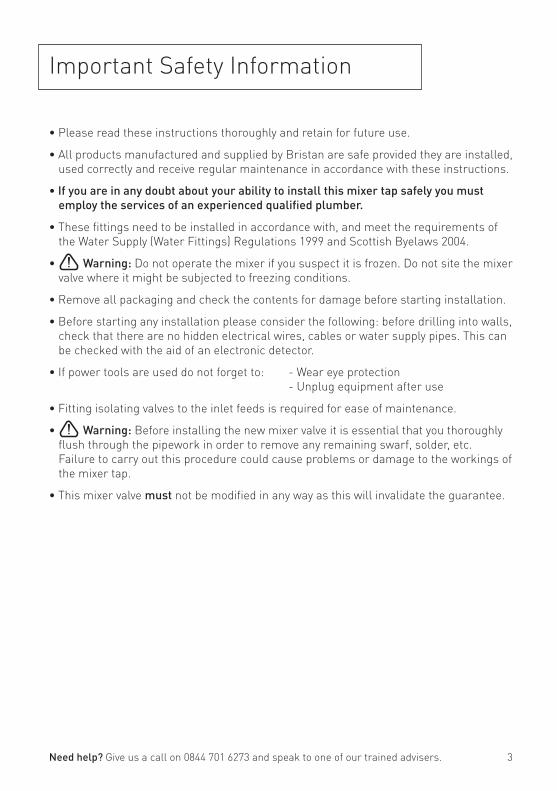
Important Safety Information
• Please read these instructions thoroughly and retain for future use.
• All products manufactured and supplied by Bristan are safe provided they are installed, used correctly and receive regular maintenance in accordance with these instructions.
• If you are in any doubt about your ability to install this mixer tap safely you must employ the services of an experienced qualified plumber.
• These fittings need to be installed in accordance with, and meet the requirements of the Water Supply (Water Fittings) Regulations 1999 and Scottish Byelaws 2004.
• Warning: Do not operate the mixer if you suspect it is frozen. Do not site the mixer valve where it might be subjected to freezing conditions.
• Remove all packaging and check the contents for damage before starting installation.
• Before starting any installation please consider the following: before drilling into walls, check that there are no hidden electrical wires, cables or water supply pipes. This can be checked with the aid of an electronic detector.
• If power tools are used do not forget to: - Wear eye protection - Unplug equipment after use
• Fitting isolating valves to the inlet feeds is required for ease of maintenance.
• Warning: Before installing the new mixer valve it is essential that you thoroughly flush through the pipework in order to remove any remaining swarf, solder, etc. Failure to carry out this procedure could cause problems or damage to the workings of the mixer tap.
• This mixer valve must not be modified in any way as this will invalidate the guarantee.
Need help? Give us a call on 0844 701 6273 and speak to one of our trained advisers.
4
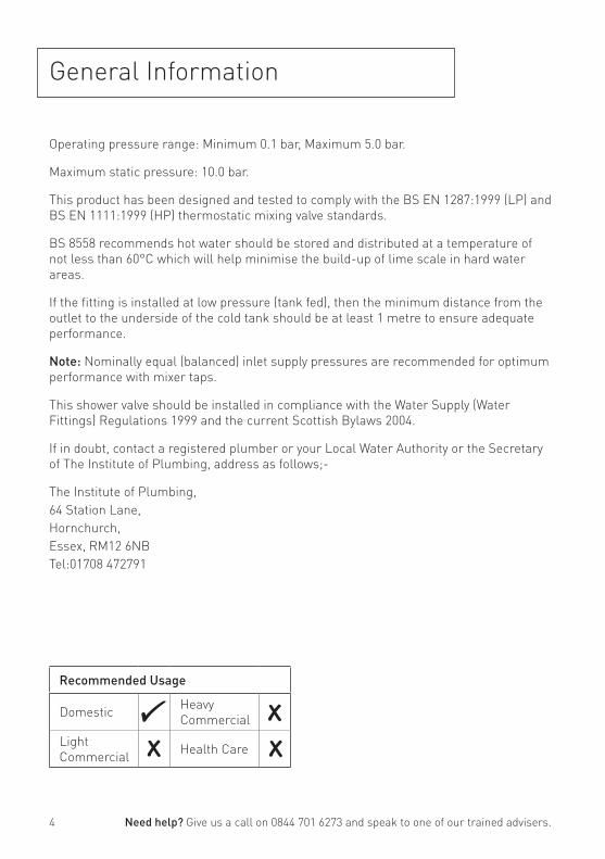
General Information
Operating pressure range: Minimum 0.1 bar, Maximum 5.0 bar.
Maximum static pressure: 10.0 bar.
This product has been designed and tested to comply with the BS EN 1287:1999 (LP) and BS EN 1111:1999 (HP) thermostatic mixing valve standards.
BS 8558 recommends hot water should be stored and distributed at a temperature of not less than 60°C which will help minimise the build-up of lime scale in hard water areas.
If the fitting is installed at low pressure (tank fed), then the minimum distance from the outlet to the underside of the cold tank should be at least 1 metre to ensure adequate performance.
Note: Nominally equal (balanced) inlet supply pressures are recommended for optimum performance with mixer taps.
This shower valve should be installed in compliance with the Water Supply (Water Fittings) Regulations 1999 and the current Scottish Bylaws 2004.
If in doubt, contact a registered plumber or your Local Water Authority or the Secretary of The Institute of Plumbing, address as follows;-
The Institute of Plumbing,64 Station Lane,Hornchurch,Essex, RM12 6NBTel:01708 472791
Recommended Usage
Domestic Heavy Commercial
Light Commercial Health Care
Need help? Give us a call on 0844 701 6273 and speak to one of our trained advisers.
5
Specifications
Need help? Give us a call on 0844 701 6273 and speak to one of our trained advisers.
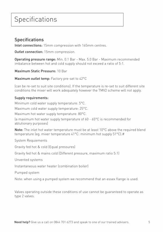
Specifications Inlet connections: 15mm compression with 165mm centres.
Outlet connection: 15mm compression.
Operating pressure range: Min. 0.1 Bar - Max. 5.0 Bar - Maximum recommended imbalance between hot and cold supply should not exceed a ratio of 5:1.
Maximum Static Pressure: 10 Bar
Maximum outlet temp: Factory pre-set to 42°C
(can be re-set to suit site conditions). If the temperature is re-set to suit different site conditions the mixer will work adequately however the TMV2 scheme will not apply.
Supply requirements: Minimum cold water supply temperature: 5°C.Maximum cold water supply temperature: 25°C.Maximum hot water supply temperature: 80°C. (a maximum hot water supply temperature of 60 - 65°C is recommended for ablutionary purposes)
Note: The inlet hot water temperature must be at least 10°C above the required blend temperature (eg. mixer temperature 41°C: minimum hot supply 51°C).#
System Requiements
Gravity fed hot & cold (Equal pressures)
Gravity fed hot & mains cold (Different pressure, maximum ratio 5:1)
Unvented systems
Instantaneous water heater (combination boiler)
Pumped system
Note: when using a pumped system we recommend that an essex flange is used.
Valves operating outside these conditions of use cannot be guaranteed to operate as type 2 valves.
6
Installation Requirements
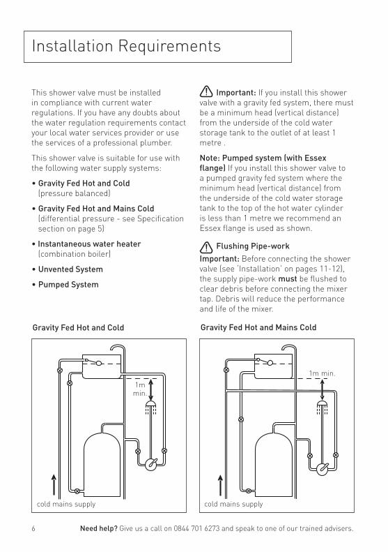
This shower valve must be installed in compliance with current water regulations. If you have any doubts about the water regulation requirements contact your local water services provider or use the services of a professional plumber.
This shower valve is suitable for use with the following water supply systems:
• Gravity Fed Hot and Cold (pressure balanced)
• Gravity Fed Hot and Mains Cold (differential pressure - see Specification section on page 5)
• Instantaneous water heater (combination boiler)
• Unvented System
• Pumped System
Gravity Fed Hot and Cold Gravity Fed Hot and Mains Cold
cold mains supply cold mains supply
Important: If you install this shower valve with a gravity fed system, there must be a minimum head (vertical distance) from the underside of the cold water storage tank to the outlet of at least 1 metre .
Note: Pumped system (with Essex flange) If you install this shower valve to a pumped gravity fed system where the minimum head (vertical distance) from the underside of the cold water storage tank to the top of the hot water cylinder is less than 1 metre we recommend an Essex flange is used as shown.
Flushing Pipe-workImportant: Before connecting the shower valve (see ‘Installation’ on pages 11-12), the supply pipe-work must be flushed to clear debris before connecting the mixer tap. Debris will reduce the performance and life of the mixer.
Need help? Give us a call on 0844 701 6273 and speak to one of our trained advisers.
1m min.1m
min.
7
Installation Requirements
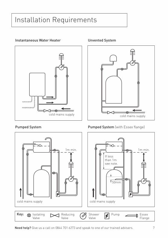
Unvented SystemInstantaneous Water Heater
Pumped System
cold mains supplycold mains supply
cold mains supply
Pumped System (with Essex flange)
cold mains supply
1m min.
Need help? Give us a call on 0844 701 6273 and speak to one of our trained advisers.
Key:
1m min.
50mm
If less than 1m see note.
Isolating Valve
Reducing Valve
Shower Valve
Pump Essex Flange

8
Installation Requirements
This fitting needs to be installed in accordance with the following Installation Requirements and Notes (IRN) to ensure they meet the requirements of the Water Supply (Water Fittings) Regulations 1999 and the Scottish Byelaws 2004.
IRN R001: See text of entry for Installation Requirements or Notes.
IRN R040 - Schedule 2-15 (1): The fitting shall be installed so that its outlet discharges above the spill-over level of any fixed appliance as indicated below:-
For backflow protection in domestic or installations up to, and including, Fluid Category 3.
If the fitting cannot be installed as indicated in the table opposite it shall be installed as either a or b below:
a: with an approved double check valve assembly or some other no less effective backflow prevention device immediately upstream of the inlet.
b: so that it draws water by gravity only from a cistern, or cylinder having a permanently open vent pipe, and the distributing pipe supplies no other fittings (other than a draining tap) at a lower level.
For backflow protection in premises or installations up to, and including Fluid Category 5.
The vertical distance of the outlet above the spill-over level shall be not less than 20mm or twice the diameter of the inlet pipe to the fitting, which ever is the greater. If the fitting cannot be installed as indicated it shall be installed with a backflow prevention arrangement suitable for the Fluid Category.
Size of tap or combination fitting
Vertical distance of outlet above spill-over level
1. Not exceeding ½” 20mm
2. Exceeding ½” but not exceeding ¾”
25mm
3. Exceeding ¾” 70mm
Need help? Give us a call on 0844 701 6273 and speak to one of our trained advisers.
9
Size of tap or combination fitting
Vertical distance of outlet above spill-over level
1. Not exceeding ½” 20mm
2. Exceeding ½” but not exceeding ¾”
25mm
3. Exceeding ¾” 70mm
Installation Requirements
Need help? Give us a call on 0844 701 6273 and speak to one of our trained advisers.
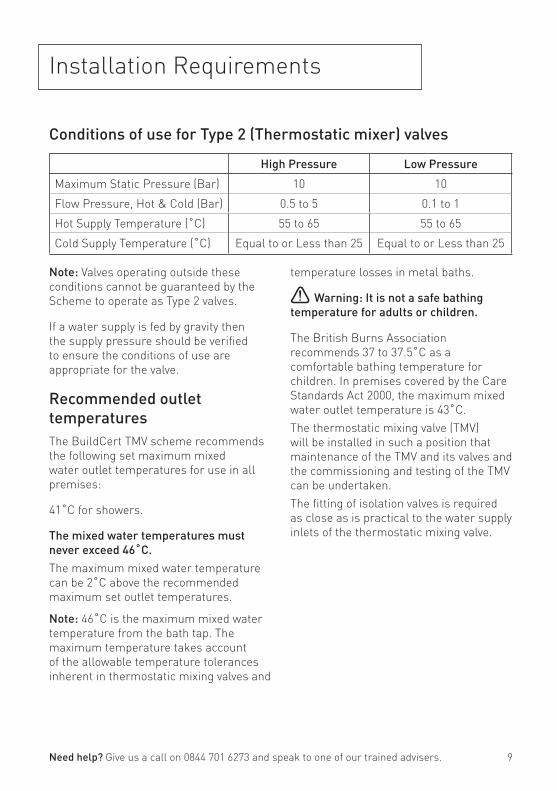
Conditions of use for Type 2 (Thermostatic mixer) valves
High Pressure Low Pressure
Maximum Static Pressure (Bar) 10 10
Flow Pressure, Hot & Cold (Bar) 0.5 to 5 0.1 to 1
Hot Supply Temperature (˚C) 55 to 65 55 to 65
Cold Supply Temperature (˚C) Equal to or Less than 25 Equal to or Less than 25
Note: Valves operating outside these conditions cannot be guaranteed by the Scheme to operate as Type 2 valves.
If a water supply is fed by gravity then the supply pressure should be verified to ensure the conditions of use are appropriate for the valve.
Recommended outlet temperaturesThe BuildCert TMV scheme recommends the following set maximum mixed water outlet temperatures for use in all premises:
41˚C for showers.
The mixed water temperatures must never exceed 46˚C.The maximum mixed water temperature can be 2˚C above the recommended maximum set outlet temperatures.
Note: 46˚C is the maximum mixed water temperature from the bath tap. The maximum temperature takes account of the allowable temperature tolerances inherent in thermostatic mixing valves and
temperature losses in metal baths.
Warning: It is not a safe bathing temperature for adults or children.
The British Burns Association recommends 37 to 37.5˚C as a comfortable bathing temperature for children. In premises covered by the Care Standards Act 2000, the maximum mixed water outlet temperature is 43˚C.The thermostatic mixing valve (TMV) will be installed in such a position that maintenance of the TMV and its valves and the commissioning and testing of the TMV can be undertaken.The fitting of isolation valves is required as close as is practical to the water supply inlets of the thermostatic mixing valve.

10
Prior to Installation
Flow Regulator removal.
This shower valve comes fitted with 2 x 8 litre per minute flow regulators fitted into each inlet elbow.
If the shower valve is installed on a low pressure system, the flow regulators may be removed.
To Remove the Flow RegulatorsUsing a suitable spanner unscrew the inlet elbows from the valve body.
Remove the flow regulators from the inlets.
Push the inserts into the inlets.
Screw the elbows onto the valve body ensuring the filter washers are fitted into the elbow fixing nuts.
Need help? Give us a call on 0844 701 6273 and speak to one of our trained advisers.
Unscrew Elbows
Tighten Elbows
Remove Flow Regulators
Fit Inserts to Inlets
11
Installation - Shower Valve
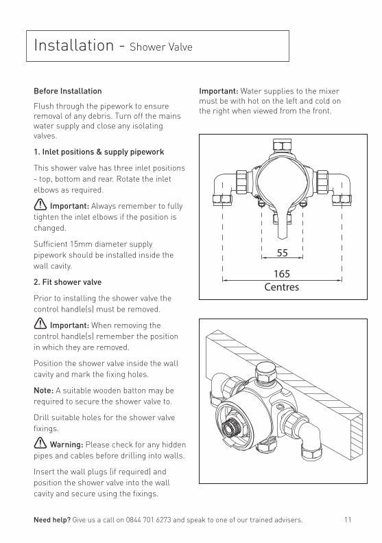
Important: Water supplies to the mixer must be with hot on the left and cold on the right when viewed from the front.
Before Installation
Flush through the pipework to ensure removal of any debris. Turn off the mains water supply and close any isolating valves.
1. Inlet positions & supply pipework
This shower valve has three inlet positions - top, bottom and rear. Rotate the inlet elbows as required.
Important: Always remember to fully tighten the inlet elbows if the position is changed.
Sufficient 15mm diameter supply pipework should be installed inside the wall cavity.
2. Fit shower valve
Prior to installing the shower valve the control handle(s) must be removed.
Important: When removing the control handle(s) remember the position in which they are removed.
Position the shower valve inside the wall cavity and mark the fixing holes.
Note: A suitable wooden batton may be required to secure the shower valve to.
Drill suitable holes for the shower valve fixings.
Warning: Please check for any hidden pipes and cables before drilling into walls.
Insert the wall plugs (if required) and position the shower valve into the wall cavity and secure using the fixings.
Need help? Give us a call on 0844 701 6273 and speak to one of our trained advisers.
55
165Centres
Unscrew Elbows
Tighten Elbows
12
Installation - Shower Valve
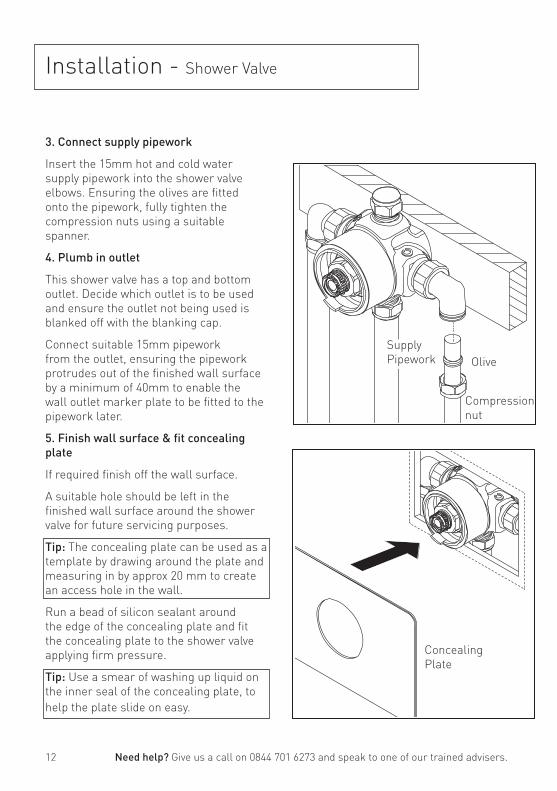
3. Connect supply pipework
Insert the 15mm hot and cold water supply pipework into the shower valve elbows. Ensuring the olives are fitted onto the pipework, fully tighten the compression nuts using a suitable spanner.
4. Plumb in outlet
This shower valve has a top and bottom outlet. Decide which outlet is to be used and ensure the outlet not being used is blanked off with the blanking cap.
Connect suitable 15mm pipework from the outlet, ensuring the pipework protrudes out of the finished wall surface by a minimum of 40mm to enable the wall outlet marker plate to be fitted to the pipework later.
5. Finish wall surface & fit concealing plate
If required finish off the wall surface.
A suitable hole should be left in the finished wall surface around the shower valve for future servicing purposes.
Tip: The concealing plate can be used as a template by drawing around the plate and measuring in by approx 20 mm to create an access hole in the wall.
Run a bead of silicon sealant around the edge of the concealing plate and fit the concealing plate to the shower valve applying firm pressure.
Tip: Use a smear of washing up liquid on the inner seal of the concealing plate, to help the plate slide on easy.
Need help? Give us a call on 0844 701 6273 and speak to one of our trained advisers.
Compression nut
OliveSupply Pipework
Concealing Plate
13
Installation - Re-fit Control Handle
Need help? Give us a call on 0844 701 6273 and speak to one of our trained advisers.
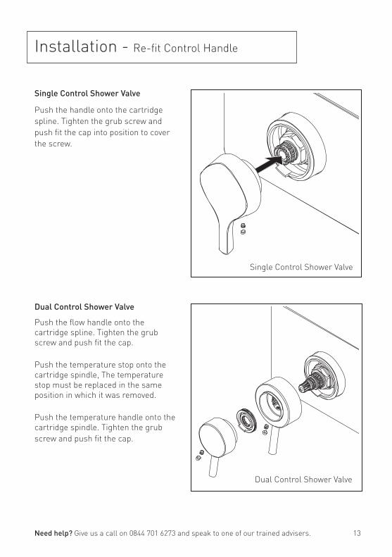
Single Control Shower Valve
Dual Control Shower Valve
Single Control Shower Valve
Push the handle onto the cartridge spline. Tighten the grub screw and push fit the cap into position to cover the screw.
Dual Control Shower Valve
Push the flow handle onto the cartridge spline. Tighten the grub screw and push fit the cap.
Push the temperature stop onto the cartridge spindle, The temperature stop must be replaced in the same position in which it was removed.
Push the temperature handle onto the cartridge spindle. Tighten the grub screw and push fit the cap.
14
Installation - Wall Outlet
Need help? Give us a call on 0844 701 6273 and speak to one of our trained advisers.
Prior to installing the wall outlet, 15mm pipework should have been installed when fitting the shower valve. Refer to pages 11-12.
Important: The pipework must be secure and rigid to ensure it does not move.
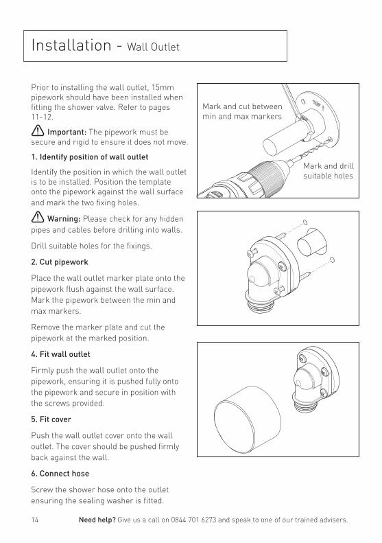
1. Identify position of wall outlet
Identify the position in which the wall outlet is to be installed. Position the template onto the pipework against the wall surface and mark the two fixing holes.
Warning: Please check for any hidden pipes and cables before drilling into walls.
Drill suitable holes for the fixings.
2. Cut pipework
Place the wall outlet marker plate onto the pipework flush against the wall surface. Mark the pipework between the min and max markers.
Remove the marker plate and cut the pipework at the marked position.
4. Fit wall outlet
Firmly push the wall outlet onto the pipework, ensuring it is pushed fully onto the pipework and secure in position with the screws provided.
5. Fit cover
Push the wall outlet cover onto the wall outlet. The cover should be pushed firmly back against the wall.
6. Connect hose
Screw the shower hose onto the outlet ensuring the sealing washer is fitted.
Mark and cut betweenmin and max markers
Mark and drill suitable holes

15
Screw the shower rose onto the arm, and the shower hose onto the diverter connection. Ensure the sealing washers are used.
3
Installation - Rigid Riser
Need help? Give us a call on 0844 701 6273 and speak to one of our trained advisers.
Fit the diverter body to the wall surface and secure in position by tightening the backnut. Connect the water supply to the diverter inlet.
1
Remove the wall bracket fixing. Secure the wall bracket to the wall surface. The bracket is adjustable to suit different wall types.
2
Positon the fixing bracket against the wall. Mark the position and remove bracket from the wall.
4
Attach the shower hose to the handset. Place the handset into the handset holder. The conical end of the hose sits into the handset holder.
To adjust the height of the handset, press in the button and slide the handset holder up or down.
5
16
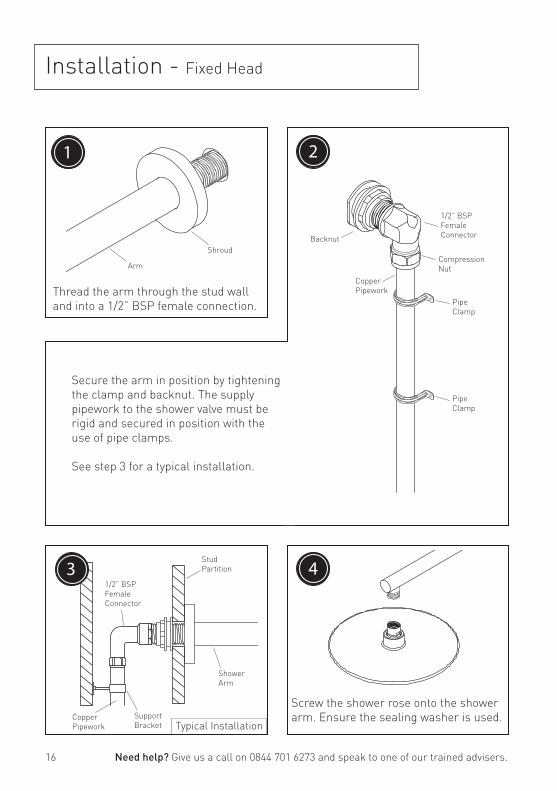
Installation - Fixed Head
Need help? Give us a call on 0844 701 6273 and speak to one of our trained advisers.
31/2” BSPFemaleConnector
StudPartition
ShowerArm
Support Bracket
Copper Pipework
1
Shroud
Arm
Thread the arm through the stud wall and into a 1/2” BSP female connection.
Screw the shower rose onto the shower arm. Ensure the sealing washer is used.
4
2
Backnut
PipeClamp
1/2” BSPFemale Connector
CompressionNut
CopperPipework
PipeClamp
Secure the arm in position by tightening the clamp and backnut. The supply pipework to the shower valve must be rigid and secured in position with the use of pipe clamps.
See step 3 for a typical installation.
Typical Installation
17
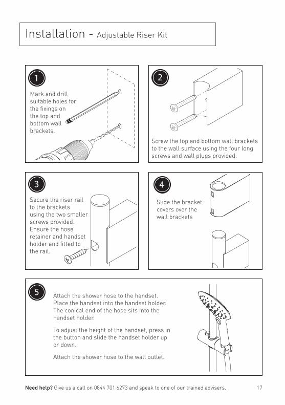
Installation - Adjustable Riser Kit
1
5
Mark and drill suitable holes for the fixings on the top and bottom wall brackets.
4
Slide the bracket covers over the wall brackets
Screw the top and bottom wall brackets to the wall surface using the four long screws and wall plugs provided.
2
Need help? Give us a call on 0844 701 6273 and speak to one of our trained advisers.
Secure the riser rail to the brackets using the two smaller screws provided.Ensure the hose retainer and handset holder and fitted to the rail.
3
Attach the shower hose to the handset. Place the handset into the handset holder. The conical end of the hose sits into the handset holder.
To adjust the height of the handset, press in the button and slide the handset holder up or down.
Attach the shower hose to the wall outlet.

18
Operating the Shower
Single Control Shower Valve
Turn the control handle clockwise to turn the flow of water on.
Continue to turn the flow lever to increase the water temperature.
Dual Control Shower Valve
Turn the flow lever clockwise to turn on the flow of water.
The further the handle is turned the greater the flow of water.
Turn the temperature lever clockwise to increase the water temperature.
The further the handle is turned the hotter the water temperature.
Need help? Give us a call on 0844 701 6273 and speak to one of our trained advisers.

19
General Cleaning Your fitting has a high quality finish and should be treated with care to preserve the visible surfaces. All surfaces will wear if not cleaned correctly, the only safe way to clean your mixer is to wipe with a soft damp cloth. Stains can be removed using washing up liquid. All bath cleaning powders and liquids will damage the surface of your fitting, even the non-scratch cleaners.
Note: Never use abrasive detergents or disinfectants or those containing alcohol, hydrochloric acid or phosphoric acid.
Commissioning
Commissioning notes for Thermostatic Mixing Valves The first step in commissioning a thermostatic mixing valve is to check the following:
1. The designation of the thermostatic mixing valve matches the application.
2. The supply pressures are within the valves operating range.
3. The supply temperatures are within the valves operating range.
4. Isolating valves (and strainers preferred) are provided.
If all these conditions are met, proceed to set the temperature as stipulated in the Maintenance section.
The mixed water temperature at the terminal fitting must never exceed 46˚C.
When commissioning / testing is due the following performance checks shall be carried out:
• Measure the mixed water temperature at the outlet.
• Carry out the cold water supply isolation test by isolating the cold water supply to the TMV, wait for five seconds, if water is still flowing check that the temperature is below 46˚C.
If there is no significant change to the set outlet temperature (+/-2˚C or less change from the original settings) and the fail-safe shut off is functioning, then the valve is working correctly and no further service work is required.
Notes: If there is a residual flow during the commissioning or the annual verification (cold water supply isolation test), then this is acceptable providing the temperature of the water seeping from the valve is no more than 2˚C above the designated maximum mixed water outlet temperature setting of the valve.
Temperature readings should be taken at the normal flow rate after allowing for the system to stabilise.
The sensing part of the thermometer probe must be fully submerged in the water that is to be tested.
Any TMV that has been adjusted or serviced must be re-commissioned and re-tested in accordance with the instructions in the Maintenance section.
The installation of thermostatic mixing valves must comply with the requirements of the Water Supply (Water Fittings) Regulations 1999.
Need help? Give us a call on 0844 701 6273 and speak to one of our trained advisers.
20
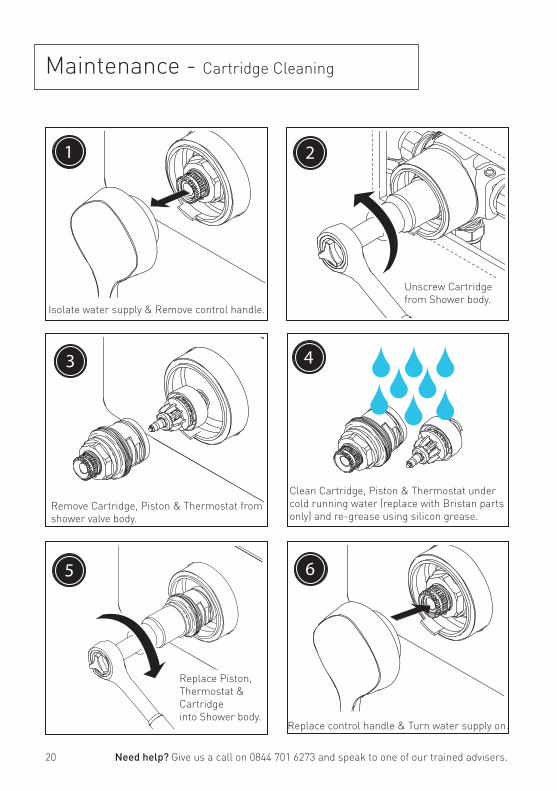
6
Replace control handle & Turn water supply on.
Maintenance - Cartridge Cleaning
Need help? Give us a call on 0844 701 6273 and speak to one of our trained advisers.
1
Isolate water supply & Remove control handle.
3
Remove Cartridge, Piston & Thermostat from shower valve body.
2
Unscrew Cartridge from Shower body.
5
Replace Piston, Thermostat & Cartridge into Shower body.
4
Clean Cartridge, Piston & Thermostat under cold running water (replace with Bristan parts only) and re-grease using silicon grease.
21
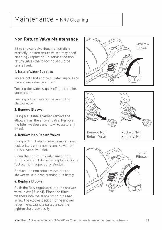
Maintenance - NRV Cleaning
Non Return Valve Maintenance
If the shower valve does not function correctly the non return valves may need cleaning / replacing. To service the non return valves the following should be carried out.
1. Isolate Water Supplies
Isolate both hot and cold water supplies to the shower valve by either;
Turning the water supply off at the mains stopcock or,
Turning off the isolation valves to the shower valve.
2. Remove Elbows
Using a suitable spanner remove the elbows from the shower valve. Remove the filter washers and flow regulators (if fitted).
3. Remove Non Return Valves
Using a thin bladed screwdriver or similar tool, prise out the non return valve from the shower valve inlet.
Clean the non return valve under cold running water. If damaged replace using a replacement supplied by Bristan.
Replace the non return valve into the shower valve elbow, pushing it in firmly.
4. Replace Elbows
Push the flow regulators into the shower valve inlets (If used). Place the filter washers into the elbow fixing nuts and screw the elbows back onto the shower valve inlets. Using a suitable spanner tighten the elbows fully.
Need help? Give us a call on 0844 701 6273 and speak to one of our trained advisers.
Unscrew Elbows
Tighten Elbows
Remove NonReturn Valve
Replace Non Return Valve
22
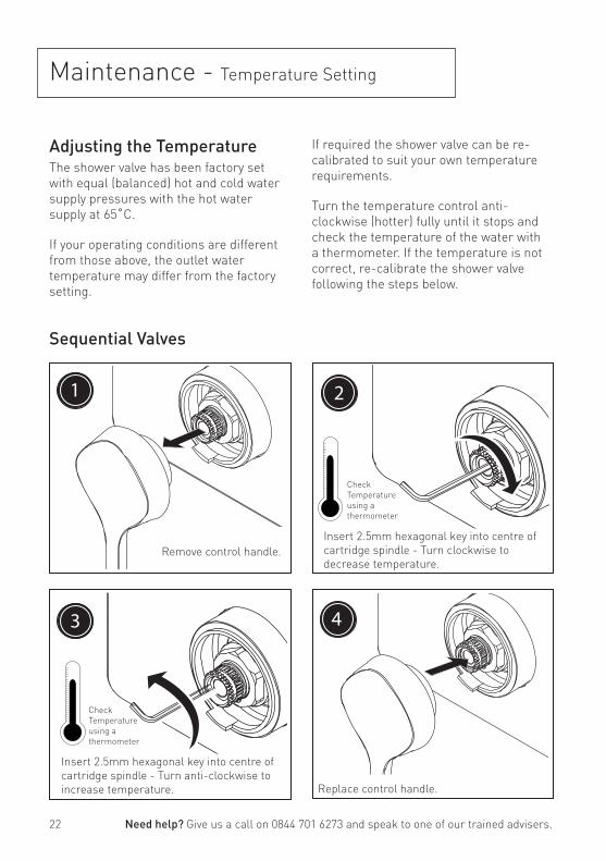
Maintenance - Temperature Setting
Adjusting the Temperature The shower valve has been factory set with equal (balanced) hot and cold water supply pressures with the hot water supply at 65˚C.
If your operating conditions are different from those above, the outlet water temperature may differ from the factory setting.
Sequential Valves
Need help? Give us a call on 0844 701 6273 and speak to one of our trained advisers.
If required the shower valve can be re-calibrated to suit your own temperature requirements.
Turn the temperature control anti-clockwise (hotter) fully until it stops and check the temperature of the water with a thermometer. If the temperature is not correct, re-calibrate the shower valve following the steps below.
1
Remove control handle.
4
Replace control handle.
3
Insert 2.5mm hexagonal key into centre of cartridge spindle - Turn anti-clockwise to increase temperature.
Check Temperatureusing a thermometer
2
Insert 2.5mm hexagonal key into centre of cartridge spindle - Turn clockwise to decrease temperature.
Check Temperatureusing a thermometer
23
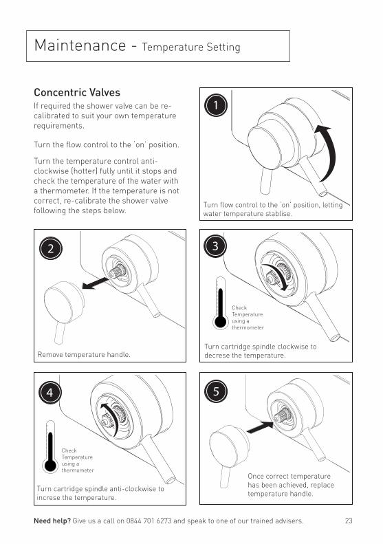
Maintenance - Temperature Setting
Need help? Give us a call on 0844 701 6273 and speak to one of our trained advisers.
5
Once correct temperature has been achieved, replace temperature handle.
Concentric ValvesIf required the shower valve can be re-calibrated to suit your own temperature requirements.
Turn the flow control to the ‘on’ position.
Turn the temperature control anti-clockwise (hotter) fully until it stops and check the temperature of the water with a thermometer. If the temperature is not correct, re-calibrate the shower valve following the steps below.
1
Turn flow control to the ‘on’ position, letting water temperature stablise.
2
Remove temperature handle.
4
Turn cartridge spindle anti-clockwise to increse the temperature.
Check Temperatureusing a thermometer
3
Turn cartridge spindle clockwise to decrese the temperature.
Check Temperatureusing a thermometer
24
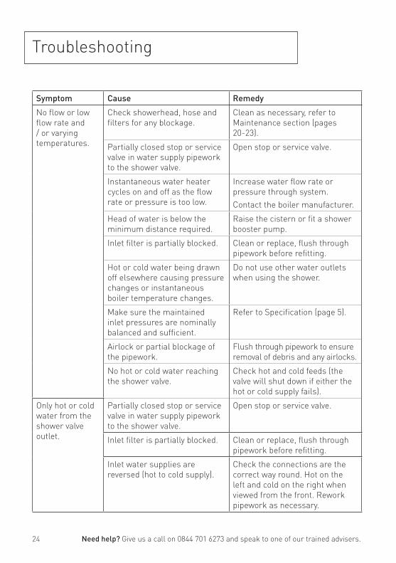
Troubleshooting
Need help? Give us a call on 0844 701 6273 and speak to one of our trained advisers.
Symptom Cause Remedy
No flow or low flow rate and / or varying temperatures.
Check showerhead, hose and filters for any blockage.
Clean as necessary, refer to Maintenance section (pages 20-23).
Partially closed stop or service valve in water supply pipework to the shower valve.
Open stop or service valve.
Instantaneous water heater cycles on and off as the flow rate or pressure is too low.
Increase water flow rate or pressure through system. Contact the boiler manufacturer.
Head of water is below the minimum distance required.
Raise the cistern or fit a shower booster pump.
Inlet filter is partially blocked. Clean or replace, flush through pipework before refitting.
Hot or cold water being drawn off elsewhere causing pressure changes or instantaneous boiler temperature changes.
Do not use other water outlets when using the shower.
Make sure the maintained inlet pressures are nominally balanced and sufficient.
Refer to Specification (page 5).
Airlock or partial blockage of the pipework.
Flush through pipework to ensure removal of debris and any airlocks.
No hot or cold water reaching the shower valve.
Check hot and cold feeds (the valve will shut down if either the hot or cold supply fails).
Only hot or cold water from the shower valve outlet.
Partially closed stop or service valve in water supply pipework to the shower valve.
Open stop or service valve.
Inlet filter is partially blocked. Clean or replace, flush through pipework before refitting.
Inlet water supplies are reversed (hot to cold supply).
Check the connections are the correct way round. Hot on the left and cold on the right when viewed from the front. Rework pipework as necessary.
25
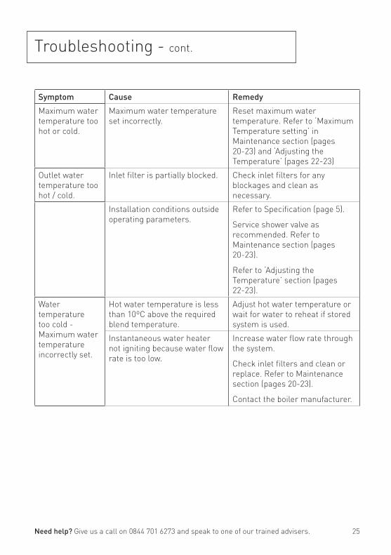
Troubleshooting - cont.
Need help? Give us a call on 0844 701 6273 and speak to one of our trained advisers.
Symptom Cause Remedy
Maximum water temperature too hot or cold.
Maximum water temperature set incorrectly.
Reset maximum water temperature. Refer to ‘Maximum Temperature setting’ in Maintenance section (pages 20-23) and ‘Adjusting the Temperature’ (pages 22-23)
Outlet water temperature too hot / cold.
Inlet filter is partially blocked. Check inlet filters for any blockages and clean as necessary.
Installation conditions outside operating parameters.
Refer to Specification (page 5).
Service shower valve as recommended. Refer to Maintenance section (pages 20-23).
Refer to ‘Adjusting the Temperature’ section (pages 22-23).
Water temperature too cold - Maximum water temperature incorrectly set.
Hot water temperature is less than 10ºC above the required blend temperature.
Adjust hot water temperature or wait for water to reheat if stored system is used.
Instantaneous water heater not igniting because water flow rate is too low.
Increase water flow rate through the system.
Check inlet filters and clean or replace. Refer to Maintenance section (pages 20-23).
Contact the boiler manufacturer.
26
Guarantee
At Bristan, we want to make things as easy as possible for our customers. That’s why we design products that are easy to fit and use, and that are quality tested to make sure they won’t let you down. It’s also why we offer solid guarantees on all products, effective from the date of purchase, to give you peace of mind.
Bristan’s shower valves are covered by a 5 year guarantee. This also includes 5 year labour cover* (subject to registration) which means that, in the unlikely event that there is a problem in the first year after purchase, we’ll send one of our expert engineers to fix it.
*Labour is provided by an approved Bristan Care engineer or appointed representative. The guarantee only applies to products with a manufacturing fault. There will be a call out charge for any incidents where no fault has been found with the product, or if the issue is due to poor installation or maintenance.
Guarantee Terms and ConditionsThis guarantee is in addition to your statutory and other legal rights and is subject to the following conditions:
• The product was purchased within the United Kingdom or Republic of Ireland.
• The guarantee applies solely to the original purchaser with proof of purchase.
• The installation must allow ready access to all products for the purpose of inspection, maintenance or replacement.
• Repair under this guarantee does not extend the original expiry date. The guarantee on any replacement parts or product ends at the original expiry date
• Any part found to be defective during the guarantee period will be replaced without charge, providing that the product has been installed in accordance with the instructions given in this guide and used as the manufacturer intended.
The guarantee does not cover
• Damage or defects caused by:
- General wear and tear (including special non-chrome finishes;
- Components such as filters, seals, ‘O’ rings and washers)
- Incorrect installation
- Repair using non-Bristan part
- Accidental or wilful misuse
- Corrosion and the use of inappropriate cleaning products.
- System debris including the build up of limescale (which can be controlled through regular servicing and maintenance)
• Compensation for loss of use of the product or consequential loss of any kind.
In the interests of continuous product improvement, Bristan reserves the right to alter product specifications without notice.
The Bristan Product Guarantee does not affect your statutory rights as a consumer.
Need help? Give us a call on 0844 701 6273 and speak to one of our trained advisers.
27
Guarantee & Service Policy
Need help?If this product does not function correctly when first used, contact Bristan Care Customer Service on 0844 701 6273 where our expert team of advisors will be able to offer you help and advice.
Problems during the guarantee periodIn the unlikely event that you encounter any problems with the product during the guarantee period, contact Bristan Care Customer Service on 0844 701 6273 with your proof of purchase and we will work to resolve the problem quickly.
Bristan Care Customer SupportBristan customers also benefit from the support of Bristan Care, our comprehensive customer support package which offers:
Technical support hotline (Tel: 0844 701 6273) with access to fully trained advisors who can offer installation advice, talk you through quick maintenance checks, or recommend the best course of action to fix any problems with a product
Expert adviceFind easy to follow ‘how to’ video guides and technical FAQs online at www.bristan.com. Our guides take you step-by-step through many product installations and you can find plenty of easy guides to quick product fixes and servicing.
Spare partsWe hold thousands of spares and we keep them for discontinued products for over seven years. Spares can easily be ordered online at www.bristan.com and are dispatched the same day.
Expert plumbing engineers If we can’t solve the problem over the ‘phone or with a spare part, then we’ll send out one of our Bristan Care engineers to take a look. Bristan Care engineers provide free support for products that are within guarantee, but are also available to service products that are out of guarantee for a small charge. For details, please call customer services on 0844 701 6273.
Need help? Give us a call on 0844 701 6273 and speak to one of our trained advisers.

28
Bristan Group Ltd. Birch Coppice Business ParkDordonTamworthStaffordshireB78 1SG Web: www.bristan.comEmail: [email protected]
A Masco Company
Part Number: FI MAXI CON
Issue: D1
Useful contact details:Customer Service:0844 7016273Customer Service Email:[email protected] Service Fax:0844 7016275Reception:0844 7016274Join us on...