INSTALLATION INSTRUCTIONS AND OWNER'S...
44
INSTALLATION INSTRUCTIONS AND OWNER'S MANUAL UNVENTED GAS FIREPLACE MODELS VFLL48SP(3,9)0L(N,P)-1 VFLZ48SP(3,9)0L(N,P)-1 GAS-FIRED UL FILE NO. MH46389 CONTEMPORARY LINEAR VENT-FREE FIREPLACE — Do not store or use gasoline or other flammable vapors and liquids in the vicinity of this or any other appliance. — WHAT TO DO IF YOU SMELL GAS • Do not try to light any appliance. • Do not touch any electrical switch; do not use any phone in your building. • Immediately call your gas supplier from a neighbor’s phone. Follow the gas supplier’s instructions. • If you cannot reach your gas supplier, call the fire department. — Installation and service must be performed by a qualified installer, service agency or the gas sup- plier. WARNING: If the information in these instructions are not followed exactly, a fire or explosion may result causing property damage, personal injury or loss of life. Installer: Leave this manual with the appliance. Consumer: Retain this manual for future reference. This appliance may be installed in an aftermarket, permanently located, manufactured (mobile) home, where not prohibited by local codes. This appliance is only for use with the type of gas indicated on the rating plate. This appliance is not convertible for use with other gases. This is an unvented gas-fired heater. It uses air (oxy- gen) from the room in which it is installed. Provisions for adequate combustion and ventilation air must be provided. Refer to pages 17 and 18. WARNING: If not installed, operated and maintained in accordance with the manufacturer's instructions, this product could expose you to substances in fuel or from fuel combustion which can cause death or serious illness. WATER VAPOR: A BY-PRODUCT OF UNVENTED ROOM HEATERS Water vapor is a by-product of gas combustion. An unvented room heater produces approximately one (1) ounce (30ml) of water for every 1,000 BTU's (.3KW's) of gas input per hour. Refer to page 17. VFLL48SP(3,9)0L(N,P)-1 VFLZ48SP(3,9)0L(N,P)-1 Page 1
Transcript of INSTALLATION INSTRUCTIONS AND OWNER'S...
INSTALLATION INSTRUCTIONSAND OWNER'S MANUAL
UNvENTEDGAS FIREpLACE
MODELSvFLL48Sp(3,9)0L(N,p)-1vFLZ48Sp(3,9)0L(N,p)-1
GAS-FIRED
UL FILE NO. MH46389
CONTEMpORARY LINEAR vENT-FREE FIREpLACE
— Donotstoreorusegasolineorotherflammablevapors and liquids in the vicinity of this or any other appliance.
— WHAT TO DO IF YOU SMELL GAS • Donottrytolightanyappliance. • Donottouchanyelectricalswitch;donotuse
anyphoneinyourbuilding. • Immediately call your gas supplier from a
neighbor’sphone.Followthegassupplier’sinstructions.
• Ifyoucannotreachyourgassupplier,callthefiredepartment.
— Installationandservicemustbeperformedbyaqualifiedinstaller,serviceagencyorthegassup-plier.
WARNING:Iftheinformationintheseinstructionsarenot followedexactly, afireorexplosionmayresult causing property damage, personal injuryor loss of life.
Installer: Leavethismanualwiththeappliance.Consumer: Retainthismanualforfuturereference.
This appliance may be installed in an aftermarket,permanently located, manufactured (mobile) home,wherenotprohibitedbylocalcodes.
This appliance is only for usewith the type of gasindicated on the rating plate. This appliance is not convertibleforusewithothergases.
Thisisanunventedgas-firedheater.Itusesair(oxy-gen)fromtheroominwhichitisinstalled.Provisionsforadequatecombustionandventilationairmustbeprovided. Refer to pages 17 and 18.
WARNING:Ifnot installed,operatedandmaintainedinaccordancewith themanufacturer's instructions,thisproductcouldexposeyoutosubstancesinfuelor from fuel combustionwhich can cause death orserious illness.
WATER vApOR: A BY-pRODUCT OF UNvENTED ROOM HEATERSWatervapor isaby-productofgascombustion.Anunventedroomheaterproducesapproximatelyone(1)ounce(30ml)ofwaterforevery1,000BTU's(.3KW's)of gas input per hour. Refer to page 17.
vFLL48Sp(3,9)0L(N,p)-1
vFLZ48Sp(3,9)0L(N,p)-1
Page 1

32925-5-0816Page 2
TABLE OF CONTENTS
IMPORTANT SAFETY INFORMATION .............................................................................3SAFETY INFORMATION FOR USERS OF LP-GAS .........................................................4IMPORTANT INSTALLATION GUIDELINES .....................................................................5INTRODUCTION ...............................................................................................................6ACCESSORIES .................................................................................................................7SPECIFICATIONS .............................................................................................................7FIREPLACE DIMENSIONS ...............................................................................................8UNPACKING THE FIREPLACE .........................................................................................8BRACKET & STANDOFF INSTALLATION ........................................................................9JUNCTION BOX WIRING INSTALLATION .................................................................10-11GAS SUPPLY ..................................................................................................................12CLEARANCES ................................................................................................................13FIREPLACE INSTALLATION ......................................................................................14-15WATER VAPOR: A BY-PRODUCT OF UNVENTED ROOM HEATERS ..........................16PROVISIONS FOR ADEQUATE COMBUSTION & VENTILATION AIR .....................16-17COMBUSTIBLE MATERIALS ..........................................................................................18CLEANING AND SERVICING .........................................................................................19MAINTENANCE ...............................................................................................................19DECORATIVE ACCESSORY INSTALLATION ...........................................................20-22MILLIVOLT CONTROL VALVE LIGHTING INSTRUCTIONS ..........................................23IP LIGHTING INSTRUCTIONS ........................................................................................24PILOT FLAME CHARACTERISTICS ...............................................................................25OPERATION INSTRUCTIONS/FLAME APPEARANCE ..................................................26MILLIVOLT WIRING ........................................................................................................27FRBC - MILLIVOLT CONTROL SYSTEM ...................................................................28-30MILLIVOLT TROUBLESHOOTING ..................................................................................31PROFLAME - IP CONTROL SYSTEM .......................................................................32-36IP OPERATING INSTRUCTIONS ....................................................................................37IP WIRING .......................................................................................................................38IP TROUBLESHOOTING ...........................................................................................39-41VFLL48SP(3,9) EXPLODED VIEW .................................................................................42VFL(L,Z)48SP(3,9) PARTS LIST .....................................................................................43WARRANTY ....................................................................................................................44MASTER PARTS DISTRIBUTOR LIST ...........................................................................45HOW TO ORDER REPAIR PARTS .................................................................................45APPLIANCE SERVICE HISTORY ..............................................................................46-47
SECTION pAGE

32925-5-0816 Page 3
IMpORTANT SAFETY INFORMATIONDANGER: Indicates a hazardous situation which, if not avoided, will
result in death or serious injury.
WARNING: Indicates a hazardous situation which, if not avoided, could result in death or serious injury.
CAUTION: Indicates a hazardous situation which, if not avoided, could result in minor or moderate injury.
NOTICE: Addresses practices not related to personal injury.• Anunventedroomheaterhavinganinputratingofmorethan
6,000Btuperhourshallnotbeinstalledinabathroom• Anunventedroomheaterhavinganinputratingofmorethan10,000
Btuperhourshallnotbeinstalledinabedroomorbathroom.• Duetohightemperatures,theapplianceshouldbelocatedoutof
trafficandawayfromfurnitureanddraperies.• Childrenandadultsshouldbealertedtothehazardofhighsurface
temperature and should stay away to avoidburnsor clothingignition.
• Youngchildrenshouldbecarefullysupervisedwhentheyareinthesameroomwiththeappliance.
• Donotplaceclothingorotherflammablematerialonorneartheappliance.
• Avoid the use of scented air fresheners (plug in type airfresheners,etc.)whilethelogsetisinoperation.Airfreshenersproducearesidueintheairsimilartocandlesandmayproduceasootlikesubstance.
• Avoidtheuseofscentedordecorativecandleswhilethelogset is in operation. Candles produce a residue in the air that createsasootlikesubstance.Burningcandleswhilethelogsetisoperatingmagnifiestheproblem.Itshouldbenotedthatcandles,ingeneral,producesoot.Theamountoftimeburnedandthequantityofcandlesburnedwilldeterminetheamountof soot produced and deposited.
• Installationandrepairshouldbedonebya qUALIFIED SERvICE pERSON. Thisapplianceshouldbeinspectedbeforeuseandatleastannuallybyaprofessionalserviceperson.Morefrequentcleaningmayberequiredduetoexcessivelintfromcarpeting,beddingmaterials,etc.Itisimperativethatcontrolcompartments,burnersandcirculatingairpassagewaysoftheappliancebekeptclean.
• DoNoTusethisroomheaterifanyparthasbeenunderwater.Immediatelycallaqualifiedservicetechniciantoinspecttheroomheaterandtoreplaceanypartofthecontrolsystemandanygascontrolwhichhasbeenunderwater.
• Youmustoperateheaterwithfireplacescreeninplace.• Donotplacetrash,logsorotherarticlesonthelogsetduring
operation.• During manufacturing, fabricating and shipping, various
componentsofthisappliancearetreatedwithcertainoils,filmsorbondingagents.Thesebondingagentsarenotharmfulbutmayproduceannoyingsmokeandsmellsastheyareburnedoffduringinitialoperationoftheappliance.Thisisanormaltemporaryoccurrence.Awindowshouldbeopenedduringtheinitialbakeoutperiod.
• Correctinstallationoftheceramicfiberlogs,properlocationofthe heater and annual cleaning are necessary to avoid potential problems with sooting. Sooting, resulting from improperinstallation or operation, can settle on surfaces outside the fireplace.Seeinstructionsforproperinstallation.
• WARNING: Do not allow fans to blow directly into thefireplace.Avoidanydraftsthatalterburnerflamepatterns.
• WARNING:Donotuseablowerinsert,heatexchangerinsertorotheraccessorynotapprovedforusewiththisheater.
• WARNING!Thisfireplaceneedsfreshairforventilationtorun properly. This fireplace has an oDS (oxygen depletionsensor)whichwillshutdowntheheaterifadequatefreshairisnotavailable.Seetroubleshootingsectionintheinstructions.
• WARNING: DO NOT operate this appliance unless all componentsincludinglogs,burners,andcontrolsareingoodworkingcondition.Neveroperatethisapplianceifanylogortwigisbroken,oroutoftheirintendedposition.RefertotheLog set placement instructions for correct log and twigpositioning. Replacement components are available through your localdealerasindicatedintheHowtoorderRepairPartssectionoftheappliancemanual.
• Keepapplianceareaclearandfreefromcombustiblematerials,gasolineandotherflammablevaporsandliquids.
• WARNING:Failuretokeeptheprimaryairopening(s)oftheburner(s)cleanmayresultinsootingandpropertydamage.
WARNINGWhenusedwithoutadequatecombustionandventilationair,heatermaygiveoffCARBoNMoNoXIDE,anodorless,poison-ous gas.
Do not install heater until all necessary provisions are madeforcombustionandventilationair.Consultthewrit-teninstructionsprovidedwiththeheaterforinformationconcerningcombustionandventilationair.Intheabsenceof instructions, refer to the National Fuel Gas Code, ANSI Z223.1/NFPA54,Air forCombustionandVentilation,orapplicablelocalcodes.
ThisheaterisequippedwithapILOT LIGHT SAFETY SYS-TEM designed to turn off the heater if not enough fresh air isavailable.
DO NOT TAMpER WITH pILOT LIGHT SAFETY SYSTEM!
If heater shuts off, do not relight until you provide fresh air.Ifheaterkeepsshuttingoff,haveitserviced.Keepburnerandcontrolcompartmentclean.
CARBoNMoNoXIDEPoISoNINGMAYLEADToDEATH.
Earlysignsofcarbonmonoxidepoisoningresembletheflu,with headache, dizziness and/or nausea. If you have thesesigns,heatermaynotbeworkingproperly.Get fresh air at once! Have heater serviced. Somepeople—pregnantwomen,personswithheartorlungdisease,anemia,thoseundertheinfluenceofalcohol,thoseat highaltitudes—aremore affectedby carbonmonoxidethan others.Thepilotlightsafetysystemsensesthedepletionofoxygenat its location. If this heater is installed in a structure having a highverticaldimension,thepossibilityexiststhattheoxygensupplyatthehigherlevelswillbelessthanthatattheheater.Inthistypeofapplication,afantocirculatethestructureairwillminimizethiseffect.Theuseofthisfanwillalsoimprovethecomfortlevelinthestructure.Whenafanisusedtocirculateair,itshouldbelocatedsothattheairflowisnotdirectedattheburner.

32925-5-0816Page 4
SAFETY INFORMATION FOR USERS OF Lp-GASPropane(LP-Gas)isaflammablegaswhichcancausefiresandexplosions.Initsnaturalstate,propaneisodorlessandcolorless.Youmaynotknowallthefollowingsafetyprecautionswhichcanprotectbothyouandyourfamilyfromanaccident.Readthemcarefullynow,thenreviewthempointbypointwiththemembersofyourhousehold.Somedaywhentheremaynotbeaminutetolose,everyone’ssafetywilldependonknowingexactlywhattodo.If,afterreadingthefollowinginformation,youfeelyoustillneedmoreinformation,pleasecontactyourgas supplier.
Lp-GAS WARNING ODOR
Ifagasleakhappens,youshouldbeabletosmellthegasbecauseoftheodorantputintheLP-Gas.
That'syoursignaltogointoimmediateaction!
• Donotoperateelectricswitches,lightmatches,useyourphone.Do not do anything that could ignite the gas.
• Geteveryoneoutofthebuilding,vehicle,trailer,orarea.Dothat IMMEDIATELY.
• Closeallgastankorcylindersupplyvalves.
• LP-Gasisheavierthanairandmaysettleinlowareassuchasbasements.Whenyouhavereasontosuspectagasleak,keepoutofbasementsandother lowareas. Stayoutuntilfirefightersdeclarethemtobesafe.
• Useyourneighbor’sphoneandcallatrainedLP-Gasservicepersonand thefiredepartment. Even thoughyoumaynotcontinue to smell gas, do not turn on the gas again. Do not re-enterthebuilding,vehicle,trailer,orarea.
• Finally, lettheservicemanandfirefighterscheckforescapedgas.Havethemairouttheareabeforeyoureturn.Properlytrained LP-Gas service people should repair the leak, thencheckandrelightthegasapplianceforyou.
NO ODOR DETECTED - ODOR FADESomepeoplecannotsmellwell.Somepeoplecannotsmelltheodorofthechemicalputintothegas.Youmustfindoutifyoucansmelltheodorantinpropane.Smokingcandecreaseyourabilitytosmell.Beingaroundanodorforatimecanaffectyoursensitivityorabilitytodetectthatodor.Sometimesotherodorsintheareamaskthegasodor.Peoplemaynotsmellthegasodorortheirmindsareonsomethingelse.Thinkingaboutsmellingagasodorcanmakeiteasiertosmell.
TheodorantinLP-gasiscolorless,anditcanfadeundersomecircumstances.Forexample,ifthereisanundergroundleak,themovementofthegasthroughsoilcanfiltertheodorant.OdorantsinLP-Gasalsoaresubjecttooxidation.Thisfadingcanoccurifthereisrustinsidethestoragetankorinirongaspipes.
The odorant in escapedgas can adsorb or absorb onto or intowalls,masonryandothermaterialsandfabricsinaroom.Thatwilltakesomeoftheodorantoutofthegas,reducingitsodorintensity.
LP-Gas may stratify in a closed area, and the odor intensity could varyatdifferentlevels.Sinceit isheavierthanair,theremaybemoreodoratlowerlevels.Alwaysbesensitivetotheslightestgasodor.Ifyoudetectanyodor,treatitasaseriousleak.Immediatelygo into action as instructed earlier.
SOME pOINTS TO REMEMBER• Learn to recognize the odor of LP-gas. Your local LP-Gas
Dealer can give you a “Scratch and Sniff” pamphlet. Use it to findoutwhatthepropaneodorsmellslike.IfyoususpectthatyourLP-Gashasaweakorabnormalodor,callyourLP-GasDealer.
• Ifyouarenotqualified,donotlightpilotlights,performservice,ormakeadjustmentstoappliancesontheLP-Gassystem.Ifyouarequalified,consciouslythinkabouttheodorofLP-Gasprior to and while lighting pilot lights or performing service or makingadjustments.
• Sometimesabasementor a closed-uphousehasamustysmell that can cover up the LP-Gas odor. Do not try to light pilotlights,performservice,ormakeadjustmentsinanareawhere the conditions are such that you may not detect the odor iftherehasbeenaleakofLP-Gas.
• Odorfade,duetooxidationbyrustoradsorptiononwallsofnewcylindersandtanks,ispossible.Therefore,peopleshouldbeparticularlyalertandcarefulwhennewtanksorcylindersareplacedinservice.Odorfadecanoccurinnewtanks,orreinstalledoldtanks,iftheyarefilledandallowedtosettoolongbeforerefilling.Cylindersandtankswhichhavebeenoutof service for a time may develop internal rust which will cause odor fade. If such conditions are suspected to exist, a periodic snifftestofthegasisadvisable. If you have any question about thegasodor, call yourLp-gas dealer. A periodic sniff test of the Lp-gasisagoodsafetymeasureunderany condition.
• If,atanytime,youdonotsmelltheLP-Gasodorantandyouthinkyoushould,assumeyouhavealeak.Thentakethesameimmediateactionrecommendedabovefortheoccasionwhenyou do detect the odorized LP-Gas.
• Ifyouexperienceacomplete“gasout,”(thecontainerisundernovaporpressure),turnthetankvalveoffimmediately.Ifthecontainer valve is left on, the container may draw in some air throughopeningssuchaspilotlightorifices.Ifthisoccurs,somenew internal rusting could occur. If the valve is left open, then treatthecontainerasanewtank.Alwaysbesureyourcon-tainerisundervaporpressurebyturningitoffatthecontainerbeforeitgoescompletelyemptyorhavingitrefilledbeforeitiscompletely empty.

32925-5-0816 Page 5
ProperPrimaryAirflowintoBurnerFor proper burner operation and flame appearance, the flow ofprimaryairintotheventuritube,locatedontherearoftheburner,mustnotbereduced.Thisflowofairisreducedifdirt,lintorotherobstructionsbuild-uparoundorinsidetheventuri.Anyobstructionintheventuritubeareamustberemoved.Theflowofairintotheventuriisalsoreducedifthegasorificeisn’tcenteredintheventuriinlet and/or is not aligned with the venturi. Any misalignment of the burnerorificemaybecorrectedbybendingtheshuttercapholdingtheorificetotheinletoftheventuritube.CeilingFans,PortableFansorLogs InstalledNearColdAirReturnsCeiling fans or oscillating floor type fans need to bemonitoredduringtheoperationofvent-freeappliance.Iftheairblowsdirectlyintotheflamecausingittodisrupttheflame,itshouldbeturnedofforredirected.Ceilingfanscouldbereversedtopossiblyeliminateflameimpingement,andthefloorfanshouldberedirected.Uponinstallation, be aware of any cold air returns or vents in theproximity of the log set. Any draft created around a vent-free log setcancausetheflametoimpingeonthelogandcreateasootingsituation.
WARNINGDonotallowfanstoblowdirectly intothefireplace.Avoidanydraftsthatalterburnerflamepatterns.
CandlesAvoidtheuseofscentedordecorativecandleswhilethefireplaceis in operation. Candles produce a residue in the air that creates a sootlikesubstance.Burningcandleswhilethelogsetisoperatingmagnifiestheproblem.Itshouldbenotedthatcandles,ingeneral,produce soot. The amount of time burned and the quantity ofcandlesburnedwilldeterminetheamountofsootproducedanddeposited.
plug-In Air FreshenersAvoid theuseofscentedair freshenerswhile thefireplace is inoperation. Air fresheners produce a residue in the air similar to candlesandmayproduceasootlikesubstance.
Television ConsiderationsInstallingatelevisionaboveafireplacehasbecomeincreasinglypopular;however,theareaaboveanyfireplacegetshotandmostTV manufacturers recommend against placing their products near a heat source.Ifyouinstallatelevisionabovethisfireplace,EmpireComfortSys-temsacceptsnoresponsibilityfordamageorinjuries.Followthetelevision manufacturer’s installation instructions, including anyrecommendations regarding proximity to heat sources.IfyouhaveaTVaboveyourfireplace, turnoff thefireplaceandletitcoolcompletelybeforeservicingortouchinganybuttonsonthe TV.
IMpORTANT INSTALLATION GUIDELINES

32925-5-0816Page 6
Notice: Duringinitialfiringofthisunit,itspaintwillbakeout,andsmokewilloccur.Topreventtriggeringofsmokealarms,ventilatethe room in which the unit is installed.Installation on Rugs and TileIf this appliance is installed directly on carpeting, tile or other combustiblematerialotherthanwoodflooringtheapplianceshallbeinstalledonametalorwoodpanelextendingthefullwidthanddepth of the appliance. Thebasereferredtoabovedoesnotmeanthefire-proofbaseasused on wood stoves. The protection is for rugs that are extremely thickandlightcoloredtile.
Solid-fuelsshallnotbeburnedinamasonryorUL 127factory-builtfireplaceinwhichanunventedroomheaterisinstalled.
QualifiedInstallingAgencyInstallationandreplacementofgaspiping,gasutilizationequipmentor accessories and repair and servicing of equipment shall beperformedonlybyaqualifiedagency.Theterm"qualifiedagency"meansanyindividual,firm,corporationorcompanywhicheitherinpersonorthrougharepresentativeisengagedinandisresponsiblefor(a)theinstallationorreplacementofgaspipingor(b)theconnection,installation,repairorservicingofequipment,whoisexperiencedinsuchwork,familiarwithallprecautionsrequiredandhascompliedwithalltherequirementsoftheauthorityhavingjurisdiction.
StateofMassachusetts:TheinstallationmustbemadebyalicensedplumberorgasfitterintheCommonwealthofMassachusetts.
Sellersofunventedpropaneornaturalgas-firedsupplementalroom heaters shall provide to each purchaser a copy of 527 CMR 30 upon sale of the unit.
In the Sate of Massachusetts, unvented propane and natural gas-firedspaceheatersshallbeprohibitedinbedroomsandbathrooms.
Theinstallationmustconformwithlocalcodesor,intheabsenceof local codes, with the National Fuel Gas Code, ANSI Z223.1.**Available from the American National Standards Institute, Inc. 1430 Broadway, New York, N.Y. 10018.
High AltitudesForaltitudes/elevationsabove2,000feet(610m),ratingsshouldbereducedattherateof4percentforeach1,000feet(305m)abovesealevel.Contactthemanufactureroryourgascompanybeforechangingspud/orificesize.
Well Head Gas InstallationsSomenaturalgasutilitiesuse"wellhead"gas.ThismayaffecttheBtu output of the unit. Contact the gas company for the heating value. Contactthemanufactureroryourgascompanybeforechangingspud/orificesize.
WARNINGThisapplianceisequippedfor(naturalgasorpropane)gas.Fieldconversion is not permitted.
Instructions to Installer1. Installer must leave instruction manual with owner after
installation.2. Installermusthaveownerfilloutandmailwarrantycardsupplied
with unvented room heater.3. Installer should show owner how to start and operate unvented
room heater.Always consult your local Building Department regarding regulations, codes or ordinances which apply to the installation of an unvented room heater.Thisappliancemaybeinstalledinanaftermarket*manufactured(mobile)home,wherenotprohibitedbystateorlocalcodes.
*Aftermarket: Completionofsale,notforpurposeofresale,fromthe manufacturer.
This appliance is only for use with the type of gas indicated on the ratingplate.Thisapplianceisnotconvertibleforusewithothergases.
WARNINGANY CHANGE TO THIS HEATER OR ITS CONTROLS CAN BE DANGEROUS. Improperinstallationoruseoftheheatercancauseseriousinjuryordeathfromfire,burns,explosionorcarbonmonoxidepoisoning.
ThisseriesisdesigncertifiedinaccordancewithAmericanNationalStandard Z21.11.2 by the Canadian Standards AssociationLaboratoriesasanUnventedRoomHeaterandshouldbeinstalledaccording to these instructions.
Any alteration of the original design, installed other than as shown in these instructions or use with a type of gas notshownontheratingplateistheresponsibilityofthepersonandcompanymakingthechange.
Millivolt 3 Series Only750MillivoltSystemWhen you ignite the pilot, the thermocouple produces millivolts (electrical current) which energizes the magnet in the gas valve. After 30 seconds to 1 minute time period you can release the gas controlknobandthepilotwillstayON.Allowyourpilotflametooperateanadditionalone(1)totwo(2)minutesbeforeyouturnthegascontrolknobfromthePILOTpositiontotheONposition.Thistimeperiodallowsthemillivolts(electricalenergy)tobuild-uptoasufficientlevelallowingthegascontroltooperateproperly.
ImportantAllcorrespondenceshouldrefertocompleteModelNumber,SerialNumberandtypeofgas.
INTRODUCTION

32925-5-0816 Page 7
Accessories for vFL(L,Z)48Sp30 (Millivolt) ModelsRemoteControl
AccessoriesDescription
FRBTC Battery Operated Remote Control with ThermostatFRBTP BatteryOperatedProgrammableRemoteControlTRW Remote Wall Thermostat (Wireless)
OpTIONAL ACCESSORIESPartNumber Description
DF48WHP Decorative Front, Tidewater - PewterDF48WBL DecorativeFront,Tidewater-BlackDF484BL DecorativeFront,4"Surround-BlackDG1AB DecorativeGlassDroplets-1/2"AquaBlue(Onekitperonesquarefoot)DG1GC DecorativeGlassDroplets-1/2"Glacier(Onekitperonesquarefoot)DG1SL DecorativeGlassDroplets-1/2"Sangria(Onekitperonesquarefoot)
DG1NXS DecorativeGlassDroplets-1"OnyxSolid(Onekitperonesquarefoot)DG1RYC DecorativeGlassDroplets-1"RubyClear(Onekitperonesquarefoot)DG1TZC DecorativeGlassDroplets-1"TopazClear(Onekitperonesquarefoot)DG1BKP DecorativeGlass,Crushed-1/4"Black(Onekitperonesquarefoot)DG1BUC DecorativeGlass,Crushed-1/4"Blue(Onekitperonesquarefoot)DG1CLF DecorativeGlass,Crushed-1/4"Clear(Onekitperonesquarefoot)DR1FMA DecorativeRock,CeramicFiber-Medium(Onekitperonesquarefoot)DRFPA DecorativeRock,CeramicFiber-Pebble(Onekitper1/2squarefoot)
LK5 120VLightingKit-RequiresSwitchorRheostat
NOTE: Thetotalburnercoverareafordecorativeglassorrocksequals2.75squarefeetforVFLL48SP,and3.00squarefeetfor VFLZ48SP.
NOTE: Neverplacedecorativeglassorrocksonornexttotheburner.Decorativeglassorrocksshouldnotbehigherthanthelipoftheburnercover.
NOTE: TheSee-Thrufireplacehasanopeningonbothsidesandtwodecorativefrontsmaybedesired.NOTE: Decorativefrontsdonotcovertheentirefaceofthefireplace.TheinstallermustfinishthewallasshowninFigure18aon
page 13.
ACCESSORIES
SpECIFICATIONSvFLL48Sp(30,90)L vFLZ48Sp(30,90)L
Lp NAT Lp NATInput Btu/hr Maximum 40,000 40,000 40,000 40,000Input Btu/hr Minimum 31,000 28,000 31,000 28,000
Orifice #49 3.00 mm #49 3.00 mmAir Shutter Opening FULL OPEN 1/8" 3/8" 1/16"
Recommended Manifold Pressure 10"w.c. 3.5"w.c. 10"w.c. 3.5"w.c.

32925-5-0816Page 8
FIREpLACE DIMENSIONS
Figure 1
Whenplanningafireplaceinsertinstallation,it’snecessarytodetermine:• Gassupplypiping(leftsideentrance).• Electricalconnections-foroptionallightkit
• Electricalsupplyrequirementsforoptionallight. (120V, 60Hz, 1 Amp) (right side entrance)
• Properopeningsizeoffireplacerequiredforinstallationofthefireplaceinsert.
vF FIREpLACE DIMENSIONS (in inches)MODEL A B C D E F G H I J K L M
VFL(L,Z)48SP 52-3/4 35 12-1/16 48 51-3/8 12-11/16 1/2 11-13/16 15/16 21-1/8 13 7-7/16 12-1/8
UNPACKINGTHEFIREPLACE1. Cutbindingstrapsandshrinkwrap.2. Remove top of carton.3. Removeglasscartonsfrombackofunitandsetaside.4. Removenon-combustibleboardsandsetaside.
5. Remove remaining carton.6. Verifythatthefireplaceandcomponentshavenotbeendam-
aged during shipping.7. Setfireplaceinalocationneartoitsfinalinstallationlocation.
Inplanningtheinstallationforthefireplace,determinewheretheunitistobeinstalledandwhetheroptionalaccessoriesaredesired.Gassupplypipingshouldalsobeplannedatthistime.Thefireplacecanbemountedonanyofthesesurfaces:1. Aflathardcombustibleornon-combustiblesurface.2. Araisedplatformofcombustibleornon-combustiblematerial.3. Fourcornersof thefireplacesocontact ismadeonall four
perimeteredgesonthebottomoftheunit.
If the fireplace is installed directly on carpeting, tile or other combustiblematerialotherthanwoodflooring,itshouldbeinstalledon a metal or wood panel extending the full width and depth of the unit.Thisunitisdesignedtobeinstalledinazero-clearanceenclosure.Thismeansthecombustiblematerialcancomeincontactwiththetopandsidestandoffspacers,andsecuredtocombustibleframingusingtheframingbracketsprovided.

32925-5-0816 Page 9
BRACKET&STANDoFFINSTALLATIoNAn optional (InnerTopDeflector)isincludedwiththefireplace.Thiscanbeusedtohelpdistributetheheatofthefireplacemoreevenlyacrossthefireplaceopening.Thisdoesnotchangetherequirementsfornon-combustiblematerialabovethefireplaceopening.
NoTE:Youmustusethestandoffsthataresuppliedwiththefireplace.Thestandoffsareshippedinaflat-stateontopofthefireplace.
1. Locatethesixsteelstandoffsundertheburnercover. See Figure 2.
Figure 2 - Standoff2. The standoffs have a perforation located on each end. Bend
them at the perforation as shown in Figure 3.
Figure3-StandoffForming4. Securethestandoffstothefireplacetopwitheightscrewsas
shown in Figure 4. The screws are located in the hardware packetinsidetheenvelopepack.Thereareholeslocatedinthetopofthefireplaceforeachtopstandoff.Theholeclosertotheedgeofthefireplaceisformountingnon-combustibleboardaroundtheopening.Theotherholesisformountingthenon-combustibleboard to thefireplace face (top,sidesandbottom).See Figures 4 and 6.
Figure4-TopofCabinet5. Onthetopandbottomofeachsidearesideframingstand-
offs.Useplierstobendthesideframingstandoffsattheper-forations90degreesawayfromthecabinet.Oncebent,thiswillleavea1/2"standoffdimension. See Figure 7.
6. Locate framing brackets in the envelope. The holes in theframing brackets allow different size boards and differentlocationsfor theboards.See Figure 5. Install eight framing bracketswithtwo10x1/2screws(each).See Figures 7 and 8.Usethefrontsetofholesifmountingaroundfireplacewin-dow.Use thebacksetofholes ifmountingaround thefire-placeface(top,sidesandbottom).See Figure 6.
NoTE:Thenon-combustibleboardprovidedis1/2"thick.Figure 5 - Nailing Flange
STANDOFF MOUNTING HOLES FOR
NON-COMUSTIBLE BOARD
AROUND WINDOW OPENING
STANDOFF MOUNTING HOLES FOR
NON-COMBUSTIBLE BOARD
AROUND OUTSIDE OF FIREPLACE
Figure6-TopofCabinet
NOTE: Bend the side standoffs at the perforations as stated in Step 5.
Figure 7
Figure 8NoTE: Additionalscrewsmadebeusedwiththeside framingbracketstogiveadditionalsupport.
(VFLL48SP shown)
(VFLL48SP shown)

32925-5-0816Page 10
JUNCTIoNBoXWIRINGINSTALLATIoNCAUTION: ALL WIRING SHOULD BE DONE BY A qUALIFIED ELECTRICIAN AND SHALL BE IN COMpLIANCE WITH ALL LoCAL,CITYANDSTATEBUILDINGCoDES.BEFoREMAK-ING THEELECTRICALCoNNECTIoN,MAKESURETHATMAIN pOWER SUppLY IS DISCONNECTED. THE AppLIANCE, WHEN INSTALLED, MUST BE ELECTRICALLY GROUNDED IN ACCORDANCE WITH LOCAL CODES OR, IN THE ABSENCE OF LOCAL CODES, WITH THE NATIONAL ELECTRICAL CODE ANSI/NFpA 70 (LATEST EDITION).
Figure 9Afactoryinstalledjunctionboxislocatedatthelowerrightcornerinsidethefireboxbottomcavity.Wiringmustbefedtothejunctionbox through the outerwrap of the fireplace, then connected asrequired inside the junctionboxasdirectedabove.Refer to theinstructionsabovetodeterminewhatwiringisneededdependingon what valve system you have, and whether or not the optional AccentLightkitwillbeinstalled.
Itisrecommendedthatapproximately6”ofwiringbeleftinthejunc-tionboxtoallowforconnections.Forwiringdetail,refertoFigure 9.
JUNCTIoNBoXWIRINGINSTALLATIoN120Voltelectricalrequirementswilldependonwhichmodelfireplaceisinstalled.ForVFL(L,Z)48SP30Lseriesmillivoltoperatedsystem: Wiring is only needed if adding the LK5 Accent Light accessory. Follow the wiring instructions included with the LK5 to connect this optional accessorythroughthejunctionboxtoawallswitch.
For VFL(L,Z)48SP90L series “IP” operated system: The suggested 120V electrical requirements include installa-tion of the electrical receptacle into the junction box lo-cated at the lower right corner inside the firebox bottom cav-ity.ThiswillbeusedtoplugintheAC/DCAdapterthatprovidespower to the electronic valve system. NOTE: IfanLK5AccentLightkitistobeinstalled,aseparate120Vlinewillbeneededtoconnectthelightkitwiringdirectlytoawallswitch. See Figure 9.Itisrecommendedtomovethefireplacetoitsfinallocationornearitbeforeinstallingelectricalwireorconnectinggaslines.
1. Toaccessand install the junctionboxandwiring,beginbyremovingtheburnercover.Liftitstraightupoffoftheburnerand set aside. See Figure 10. For VFLL48SP90 Units: Remove the heat shield and disconnect the wire to the switch on the heat shield.
2. Removethefive5/16”Hexscrewsthatholddownthecompleteburnerandvalveassembly.Therearethreescrewsonthefrontbottomflange,andtwoonthebackbottomflange,neartheends. See Figure 11.
Figure 10
Figure 11
(VFLL48SP shown)
vFLL48Sp(3,9)0L(N,p)-1
vFLZ48Sp(3,9)0L(N,p)-1

32925-5-0816 Page 11
3. Liftthecompleteburnerandvalveassemblyupward,thenturnit sideways in fireplaceopening togaineasyaccess to thejunctionbox. YoumayremovethecompleteburnerandvalveassemblyasshowninFigure 12.
Figure 12
4 Thejunctionboxislocatedontheendofthefireplace.Removethe5/16”Hexscrewthatsecuresthejunctionboxtothefirebox,andremovethejunctionbox.See Figure 13. Run romex wire throughtherightrearcornerofthefireplaceandintothefireboxarea.Securewiringwiththeromexconnectorasrequiredandinstall the duplex receptacle as shown in Figure 14. Attach the blackwiretothebrassscrewsideofthereceptacle,andthewhite wire to the opposite side. Secure the incoming ground wire under the green ground screw provided on the receptacle.
Figure 13
Figure 145. IfonlyinstallingtheLK5AccentLightkit,thenremovethe7/8”
diameterknockoutinthesideofthejunctionbox,installthe7/8” diameter protective grommet, and connect the wiring with wire nuts as shown in Figure 14.
ThereisasolidjunctionboxcoverplateincludedwiththeLK5kitthatshouldbeusedonthejunctionboxifaduplexreceptacle is not used.
6. Oncethejunctionboxwiringiscompleted,re-installthejunc-tionboxintothelowerrightcornerofthefireboxcavityusingthe screws removed in step 4 as shown in Figure 15.
USED FOR LIGHT
ACCESSORY ONLY
Figure 157. Reinstalltheburnerandvalveassemblyandreattachthescrews
removed in step 2. See Figure 11.8. For VFL(L,Z)48SP90: Reconnect the wire from the switch on
theheatshieldandputtheshieldbackinplace.
JUNCTIoNBoXWIRINGINSTALLATIoN
(VFLL48SP shown)

32925-5-0816Page 12
GAS SUppLYThegaspipelinecanbebroughtinthroughtherightorleftsideofthe appliance. The insert has a Flexline with shutoff valve located on the left side when facing the unit. See Figures 16 and 17. Consult the current National Fuel Gas Code, ANSI Z223.1 CAN/CGA-B149 (.1 or .2) installation code.
RecommendedGasPipeDiameter
pipe Length Schedule 40 pipe InsideDiameter
Tubing,TypeLoutsideDiameter
Nat. L.P. Nat. L.P.
0-10ft0-3m
1/2"12.7mm
3/8"9.5mm
1/2"12.7mm
3/8"9.5mm
11-40ft4-12m
1/2"12.7mm
1/2"12.7mm
5/8"15.9mm
1/2"12.7mm
41-100ft13-30m
1/2"12.7mm
1/2"12.7mm
3/4"19mm
1/2"12.7mm
101-150ft31-46m
3/4"19mm
1/2"12.7mm
7/8"22.2mm
3/4"1.9 mm
Caution:Neveruseplasticpipe.Checktoconfirmwhetheryourlocalcodesallowcoppertubingorgalvanized.Notice: Since some municipalities have additional local codes, it isalwaysbesttoconsultyourlocalauthorityandinstallationcode.The use of the following gas connectors is recommended:— ANSZ21.24ApplianceConnectorsofCorrugatedMetalTubing
and Fittings.— ANSZ21.45AssembledFlexibleApplianceConnectorsofOther
Than All-Metal ConstructionTheaboveconnectorsmaybeusedifacceptablebytheauthorityhaving jurisdiction. The state of Massachusetts requires that aflexibleapplianceconnectorcannotexceedthreefeetinlength.
Figure 16
InstallingtheMainGasCockEachapplianceshouldhaveitsownmanualgascock.Amanualmaingascockshouldbelocatedinthevicinityoftheunitandcanbeeasilyaccessedafterassembly.Wherenoneexists,orwhere its sizeor location isnotadequate, contact your localauthorized installer for installation or relocation.Compoundsusedonthreadedjointsofgaspipingshallberesistanttotheactionofliquefiedpetroleumgases.Thegaslinesmustbecheckedforleaksbytheinstaller.Thisshouldbedonewithasoapsolutionwatchingforbubblesonallexposedconnections,andifunexposed,apressuretestshouldbemade.Neveruseanexposedflametocheckforleaks.Appliancemustbedisconnectedfrompipingatinletofcontrolvalveandpipecappedorpluggedforpressuretest.Neverpressuretestwithapplianceconnected;controlvalvewillsustaindamage!Notice: Themillivoltgascontrolsareequippedwithacapturedscrewtype pressure test point, therefore it is not necessary to provide a 1/8"testpointupstreamofthecontrol.
Whenusingcopperorflexconnectoruseonlyapprovedfittings.Theapplianceandit’sindividualshutoffvalvemustbedisconnectedfrom supply piping system during any pressure testing of that system attestpressuresinexcessof1/2psig(3.5kPa).Theappliancemustbeisolatedfromthegassupplypipingsystembyclosingitsindividualmanualshutoffvalveduringanypressuretestingofthegassupplypipingsystemattestpressuresequaltoorlessthan1/2psig(3.5kPa).Attention! If one of the procedures results in pressures in excess of 1/2psig(14"w.c.)(3.5kPa)onthefireplacegasvalve,itwillresultin a hazardous condition.
Figure 17Shutoffvalvemustbeaccessibleafterinstallation.
CheckingManifoldPressureMILLIvOLT vALvES (vFL(L,Z)48Sp30)Natural gaswillhaveamanifoldpressureofapproximately3.5"w.c.formaximuminputor1.6"w.c.forminimuminputatthepressureregulator outlet with the inlet pressure to the pressure regulator fromaminimumof4.5"w.c.forthepurposeofinputadjustmenttoamaximumof10.5"w.c.propane gas willhaveamanifoldpressureapproximately10.0"w.c.(2.49kPa)formaximuminputor6.3"w.c.forminimuminputatthepressure regulator outlet with the inlet pressure to the pressure regulator from aminimum of 11.0"w.c. for the purpose of inputadjustmenttoamaximumof13.0"w.c.
INTERMITTENT pILOT vALvES (vFL(L,Z)48Sp90)Natural gaswillhaveamanifoldpressureofapproximately3.5"w.c. at the pressure regulator outlet with the inlet pressure to the pressureregulatorfromaminimumof7.0"w.c.forthepurposeofinputadjustmenttoamaximumof10.5"w.c.propane gas willhaveamanifoldpressureapproximately10.0"w.c.at the pressure regulator outlet with the inlet pressure to the pressure regulator from aminimum of 11.0"w.c. for the purpose of inputadjustmenttoamaximumof13.0"w.c.A test gage connection is located downstream of the gas appliance pressure regulator for measuring gas pressure. The connection is a 1/8 inch N.P.T. plugged tapping.
Millivolt Control valveThevalveregulatorcontrolstheburnerpressurewhichshouldbecheckedatthepressuretestpoint.Turncapturedscrewcounterclockwise2or3turnsandthenplacetubingtopressuregaugeovertestpoint(Usetestpoint“A”closesttocontrolknob).See Figure 42.After taking pressure reading,besure and turn capturedscrewclockwisefirmly to re-seal.Donotover torque.Checkforgasleaks.
32925-5-0816 Page 13
CLEARANCES
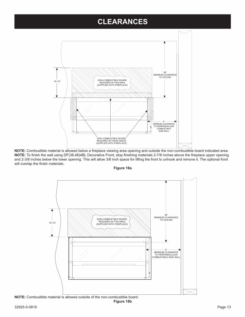
NOTE: Combustiblematerialisallowedbelowafireplaceviewingareaopeningandoutsidethenon-combustibleboardindicatedarea.NOTE: TofinishthewallusingDF(38,48)4BLDecorativeFront,stopfinishingmaterials2-7/8inchesabovethefireplaceupperopeningand2-3/8inchesbelowtheloweropening.Thiswillallow3/8inchspaceforliftingthefronttounhookandremoveit.Theoptionalfrontwilloverlapthefinishmaterials.
Figure 18a
NOTE: Combustiblematerialisallowedoutsideofthenon-combustibleboard.Figure18b

32925-5-0816Page 14
Figure 19
DIMENSION (IN INCHES)MODEL A B C D E FvFL(L,Z)48 21 23 25 27 29 31
Television ConsiderationsInstallingatelevisionaboveafireplacehasbecomeincreasinglypopular;however,theareaaboveanyfireplacegetshotandmostTV manufacturers recommend against placing their products near a heat source.Ifyouinstallatelevisionabovethisfireplace,EmpireComfortSys-temsacceptsnoresponsibilityfordamageorinjuries.Followthetelevision manufacturer’s installation instructions, including anyrecommendations regarding proximity to heat sources.IfyouhaveaTVaboveyourfireplace, turnoff thefireplaceandletitcoolcompletelybeforeservicingortouchinganybuttonsonthe TV.
CLEARANCES

32925-5-0816 Page 15
WallThermostatConsiderationsForoptimalperformance,thethermostatshouldbeinstalledintheroom with the appliance and the highest ceiling.
Built-In Fireplace InstallationBuilt-ininstallationofthisfireplaceinvolvesinstallingthefireplaceintoa framed-inenclosure.Thismakesthefrontof thefireplaceflushwithawallorthefrontofthefireplacewindowflushwithawall.
Frame in rough opening. Use dimensions shown in Figure 22 for a conventional rough opening. Use Figure 23 for an elevated instal-lation.Besure toprovidesupport to thebottomof thefireplace.Besuretoprovidegas lineforfireplaceandelectricalpowerforoptional lightassembly.Refer toJunctionBoxWiringsectiononpages10and11fordetailsonelectricalrequirements.1. Verifygasandelectricallinesarereadyforfireplaceinstalla-
tion.See"GasSupply"page12.See"JunctionBox"pages10and11.Ifnoelectricalpoweristobeused,placeasolidcover(provided)over the junctionboxopening.SeeJunctionBoxWiring section in this manual.
2. Insertfireplaceintoenclosure.3. Levelfirebox.4. Securesixframingbracketswithdrywallscrewstotheframed
openingabovethefireplaceasshown inFigures 20 to 23. Topbracketsshouldbe installed tosupport theendsof thenon-combustibleboard.Note:Thedrywallscrewsarelocatedin the instructionenvelopepacket.Secure the leftandrightstandoffs to the side framing as shown in Figure 20. Secure thefireplaceontheleftandrightthroughtheframingbrack-ets.
5a. Toinstallthefireplacecabinetfaceflushwiththewall-board,securetheframingbracketsatthetopandsidesofthefire-placewitha1/2"setback.Thisallowsyoutousethesuppliednon-combustibleboardabovethefireplace.Note:Thistypeofinstallationwillallowyoutoapplytile,marble,stoneorothernon-combustiblematerialoverthefaceofthefireplacecabi-net,uptotheflangeopening.SeeFigure18b.Note: Decora-tive fronts do not cover the entire face of the unit.
NOTE: Decorative fronts do not cover the entire face of thefireplace.The installermustfinishthewallasshowninFigure 18a on page 13.5b. To install the fireplace so that non-combustible board is in-
stalledoverthefireplacecabinetface(uptotheopeningwin-dow),securethetopandsideframingbracketsflushwiththefaceofthefireplacecabinet.Note:Withthisoptionadditionalnon-combustiblematerialswillbeneededtoextendoverthefaceof thefireplacecabinet,aboveandbeside theflangedopening.Non-combustibleboardhasbeensentwiththeunit.Attach these pieces to the face of the unit with high tempera-ture silicone adhesive or with screws. If putting screws into the face of the unit, avoid the area around the outer glass. See Figure 18a.
FIREpLACE INSTALLATIONNotice for Finishing Materials
Thewall above thefireplacewill becomehot. Install thenon-combustible board supplied with the fireplace before addingpaint,tileorstone.Attachtileorothernon-combustibleproductstothefireplacefaceandtothenon-combustiblearea(Figures18a and 18b) using adhesives designed for high-temperatureapplications. Follow the manufacturer's instructions for applica-tionandcuringtimes.Heatfromthefireplacemaycauseincor-rectly installedmaterials to fail. If you are painting above thefireplace,useacoatingdesignedforhightemperatureenviron-ments and follow the manufacturer's instructions for surface prep,applicationandcuring.Heatfromthefireplacemaycauseincorrectly applied coatings to fail or discolor.
6. Checkgaslinesforleaks.7. ForVFL(L,Z)48SP90plugpoweradaptertojunctionbox.8. Placebatteriesinreceiverboxesandremotesusinginstruc-
tions provided. Verify remotes are communicating with receiv-ers.
9. Install optional liners using their instructions.10a.ForVF(L,Z)48SP30fireplaces:Connecttheremotereceiver
to the valve as indicated in the instructions included with the remote and receiver. Light the pilot (see page 23) and turn the valve to the "ON"position.Set "Hi"or "Lo" forflameheightasdesired.Thefireplacewillnotlighttheburneruntilthere-mote's"ON"buttonispressed.
10b.ForVF(L,Z)48SP90fireplaces,setreceiverfor"remote".Seepage 30. Set switch on heat shield to standing pilot or inter-mediate pilot. See Figure 62. Verify that the heat shield is backinplace. See Figure 10.
11. Replaceburnercover.See Figure 10.12. Retrieveshorterglassandinstallonbothsidesofburner.See
Figure 20.13. Place optional decorative glass or rocks according to their
instruction. See Figure 34. Glass and rockmust not beplacedontopofornexttoburner.
14. Retrieve larger glass panel and install in slots on the left and rightoffireplace.See Figures 35 - 37.
15. Installoptionaldecorativesurroundpanelassembly.Refertoinstructionsincludedwiththesurroundpanelkit.
16. Testfireplaceusingremoteandshowownerhowtousetheremote. Show owner lighting instructions in this manual.
17. Installationofbuilt-infireplaceiscomplete.Leavethismanualwith the owner.
Figure 20
32925-5-0816Page 16
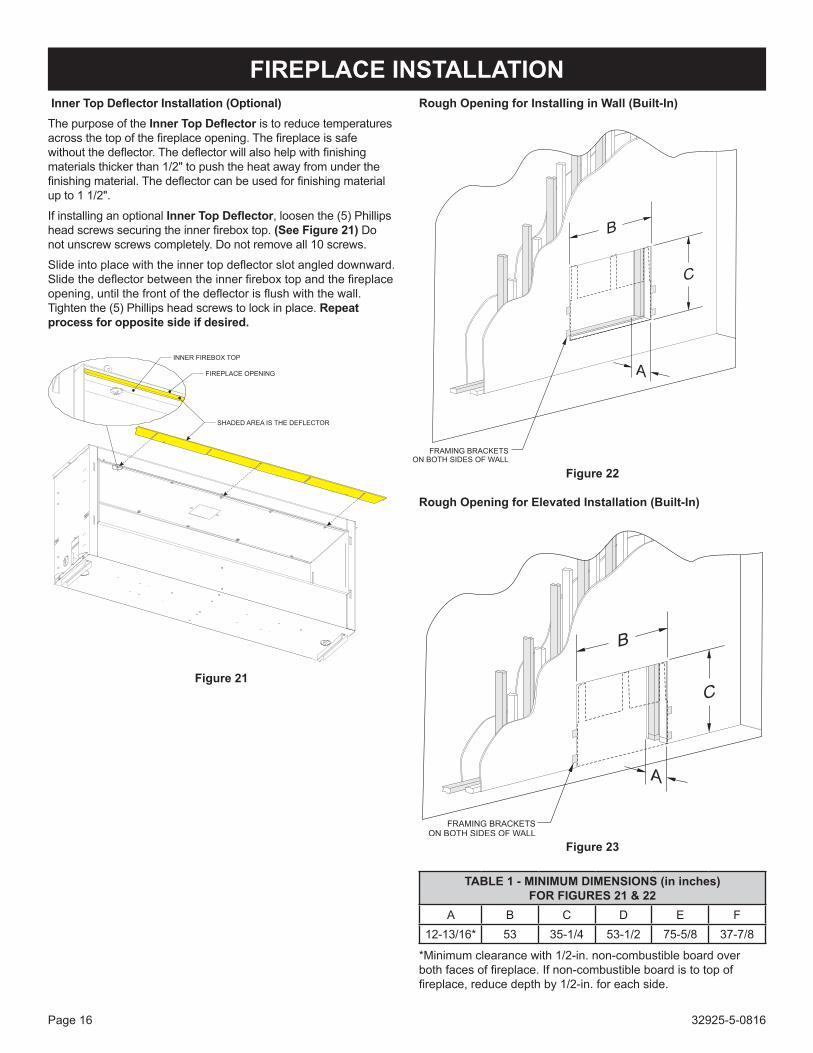
FIREpLACE INSTALLATION InnerTopDeflectorInstallation(optional)The purpose of the InnerTopDeflector is to reduce temperatures acrossthetopofthefireplaceopening.Thefireplaceissafewithoutthedeflector.Thedeflectorwillalsohelpwithfinishingmaterialsthickerthan1/2"topushtheheatawayfromunderthefinishingmaterial.Thedeflectorcanbeusedforfinishingmaterialupto11/2".
If installing an optional InnerTopDeflector, loosen the (5) Phillips headscrewssecuringtheinnerfireboxtop.(See Figure 21) Do not unscrew screws completely. Do not remove all 10 screws.
Slideintoplacewiththeinnertopdeflectorslotangleddownward.Slidethedeflectorbetweentheinnerfireboxtopandthefireplaceopening,untilthefrontofthedeflectorisflushwiththewall.Tightenthe(5)Phillipsheadscrewstolockinplace.Repeat process for opposite side if desired.
SHADED AREA IS THE DEFLECTOR
INNER FIREBOX TOP
FIREPLACE OPENING
Figure 21
Rough Opening for Installing in Wall (Built-In)
Figure 22
Rough Opening for Elevated Installation (Built-In)
Figure 23
TABLE 1 - MINIMUM DIMENSIONS (in inches) FoRFIGURES21&22
A B C D E F12-13/16* 53 35-1/4 53-1/2 75-5/8 37-7/8
*Minimumclearancewith1/2-in.non-combustibleboardoverbothfacesoffireplace.Ifnon-combustibleboardistotopoffireplace,reducedepthby1/2-in.foreachside.

32925-5-0816 Page 17
Watervaporisaby-productofgascombustion.Anunventedroomheater produces approximately one (1) ounce (30ml) of water for every 1,000 BTU's (.3KW's) of gas input per hour. Unvented room heaters are recommended as supplemental heat (a room) rather than a primary heat source (an entire house). In most supplemental heat applications, the water vapor does not create a problem.Inmostapplications,thewatervaporenhancesthelowhumidity atmosphere experienced during cold weather.
The following steps will help insure that water vapor does not becomeaproblem.1. Be sure the heater is sized properly for the application, including
amplecombustionairandcirculationair.2. Ifhighhumidityisexperienced,adehumidifiermaybeusedto
help lower the water vapor content of the air.3. Do not use an unvented room heater as the primary heat
source.
Thisheatershallnotbeinstalledinaconfinedspaceorunusuallytight construction unless provisions are provided for adequatecombustionandventilationair.
InstallationinaConfinedSpaceAconfinedspaceisanareawithvolumelessthan50cubicfeetper1,000Btuhofthecombinedinputratesofallappliancesdrawingcombustionair fromthatspace.Smallareassuchasequipmentroomsareconfinedspaces.Furnacesinstalledinaconfinedspacewhich supply heated air to areas outside the space must draw return air from outside the space through tightly sealed return air ducts. A confinedspacemusthave2openingsintothespaceforcombustionair.Oneopeningmustbewithin12inchesoftheceilingandtheothermustbewithin12inchesofthefloor.Therequiredsizingoftheseopeningsisdeterminedbywhetherinsideoroutsideair isusedtosupportcombustion,themethodbywhichtheairisbroughttothespace(verticalorhorizontalduct)andbythetotalinputrateof all appliances in the space.
Unusually Tight ConstructionTheairthatleaksarounddoorsandwindowsmayprovideenoughfreshairforcombustionandventilation.However,inbuildingsofunusually tight construction, you must provide additional fresh air. Unusually tight construction is defined as construction
where:a. Walls and ceilings exposed to the outside atmosphere have
a continuous water vapor retarder with a rating of one perm orlesswithopeningsgasketedorsealed,and
b. Weather-strippinghasbeenaddedonopenablewindowsand doors, and
c. Caulking or sealants are applied to areas such as jointsaroundwindowanddoorframes,betweensoleplatesandfloors,betweenwall-ceilingjoints,betweenwallpanels,atpenetrationsforplumbing,electrical,andgaslines,andatother openings.
Ifyourhomemeetsallofthethreecriteriaabove,youmustprovide additional fresh air. See “Ventilation Air FromOutdoors,” page 18.
DeterminingifYouHaveaConfinedorUnconfinedSpaceUsethisworksheettodetermineifyouhaveaconfinedorunconfinedspace.Space: Includes the room in which you will install heater plus any adjoining rooms with doorless passageways or ventilation grills betweentherooms.
1. Determine the volume of the space (length x width x height). Length x Width x Height = cu. ft. (volume of
space)Example: Space size 16 ft. (length) x 10 ft. (width) x 8 ft. (ceiling
height) = 1,280 cu. ft. (volume of space) If additional ventilation to adjoining room is supplied with grills
or openings, add the volume of these rooms to the total volume of the space.
2. Divide thespacevolumeby50cubic feet todetermine themaximum BTU/Hr the space can support.
(volume of space) ÷ 50 cu. ft. = (maximum BTU/Hr the space can support)
Example: 1,280 cu. ft. (volume of space) ÷ 50 cu. ft. = 25.6 or 25,600 (maximum BTU/Hr the space can support)
3. AddtheBTU/Hrofallfuelburningappliancesinthespace. Vent-free heater BTU/Hr Gas water heater BTU/Hr Gas furnace BTU/Hr Vented gas heater BTU/HrGasfireplacelogs BTU/Hr Other gas appliances* + BTU/Hr Total = BTU/Hr
Example: Vented gas heater 20,000 BTU/Hr Vent-free heater + 18,000 BTU/Hr Total = 38,000 BTU/Hr*Do not include direct-vent gas appliances. Direct vent draws combustionairfromtheoutdoorsandventstotheoutdoors.
4. Compare the maximum BTU/Hr the space can support with the actual amount of BTU/Hr used.
BTU/Hr (maximum the space can support) BTU/Hr (actual amount of BTU/Hr used) Example: 25,600 BTU/Hr (maximum the space can support) 38,000 BTU/Hr (actual amount of BTU/Hr used)
WARNINGIftheareainwhichtheheatermaybeoperatedissmallerthanthatdefinedasanunconfinedspaceorifthebuildingisofunusuallytightconstruction,provideadequatecombustionandventilationairbyoneof themethodsdescribed in theNational Fuel Gas Code, ANSI Z223.1/NFPA 54, Air for Combustion and Ventilation, orapplicablelocalcodes.
WATER vApOR: A BY-pRODUCT OF UNvENTED ROOM HEATERS
PRoVISIoNSFoRADEQUATECoMBUSTIoN&VENTILATIoNAIR

32925-5-0816Page 18
PRoVISIoNSFoRADEQUATECoMBUSTIoN&VENTILATIoNAIR(continued)
Thespaceintheaboveexampleisaconfinedspacebecausetheactual BTU/Hr used is more than the maximum BTU/HR the space can support. You must provide additional fresh air. Your options are as follows:A. Reworkworksheet,addingthespaceofanadjoiningroom.If
theextraspaceprovidesanunconfinedspace,removedoortoadjoiningroomoraddventilationgrillsbetweenrooms.SeeVentilationAirFromInsideBuilding.
B. Vent room directly to the outdoors. See VentilationAirFromOutdoors.
C. InstallalowerBTU/Hrheater,iflowerBTU/Hrsizemakesroomunconfined.
If the actual BTU/Hr used is less than the maximum BTU/Hr the spacecansupport,thespaceisanunconfinedspace.Youwillneedno additional fresh air ventilation.
WARNINGYoumustprovideadditionalventilationairinaconfinedspace.
ventilation AirVentilationAirFromInsideBuildingThisfreshairwouldcomefromanadjoiningunconfinedspace.Whenventilatingtoanadjoiningunconfinedspace,youmustprovidetwopermanentopenings:onewithin12"oftheceilingandonewithin12"oftheflooronthewallconnectingthetwospaces(See Options 1 and 2, Figure 24). You can also remove door into adjoining room (see option 3, Figure 24). Each ventilation grill or opening shall haveaminimumfreeareaofonesquareinchper1,000BTUHofthetotalinputratingofthegasequipmentintheconfinedspace.
Figure 24
WARNINGRework worksheet, adding the space of the adjoiningunconfinedspace.Thecombinedspacesmusthaveenoughfreshairtosupplyallappliancesinbothspaces.
VentilationAirFromoutdoorsProvideextrafreshairbyusingventilationgrillsorducts.Youmustprovidetwopermanentopenings:onewithin12"oftheceilingandonewith12"ofthefloor.Connecttheseitemsdirectlytotheoutdoorsor spaces open to the outdoors. These spaces include attics and crawl spaces. In most cases for direct communication with the outdoors or direct communication through a vertical duct a free areaopeningofonesquareinchper4,000BTU/Hrofheaterinputrating for each grill. If a horizontal duct is used, a grill free area or ductopeningshallhaveafreeareaopeningofonesquareinchper2,000 BTU/Hr for each grill. Follow the National Fuel Code ANSI Z223.1/NFPA54, Air for Combustion and Ventilation for requiredsize of ventilation grills or ducts.IMPORTANT: Do not provide openings for inlet or outlet air into attic if attic has a thermostat-controlled power vent. Heated air entering the attic will activate the power vent.
Figure 25
A1 A2
B1 B2
A1 x B1 = C1A2 x B2 = C2C1+C2=Sq.In.Required
Example:Fora30,000BTUHeater,1sqinper1,000BTUequals30sq.in.ofopening.
(A1) 5in2 x (B1) 3in2 = (C1) 15in2
(A2) 5in2 x (B2) 3in2 = (C2) 15in2
(C1) 15in2 + (C2) 15in2 = 30in2
Figure 26
32925-5-0816 Page 19
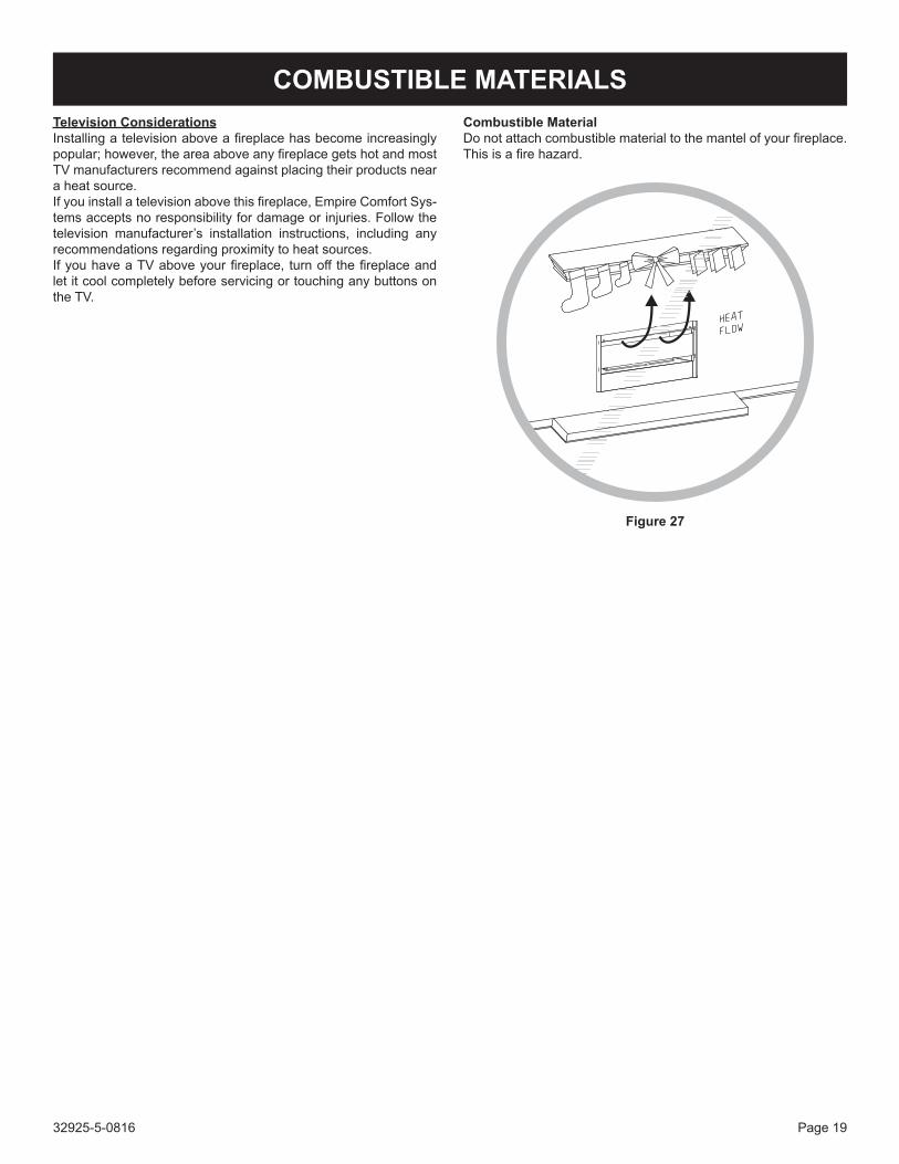
COMBUSTIBLE MATERIALSTelevision ConsiderationsInstallingatelevisionaboveafireplacehasbecomeincreasinglypopular;however,theareaaboveanyfireplacegetshotandmostTV manufacturers recommend against placing their products near a heat source.Ifyouinstallatelevisionabovethisfireplace,EmpireComfortSys-temsacceptsnoresponsibilityfordamageorinjuries.Followthetelevision manufacturer’s installation instructions, including anyrecommendations regarding proximity to heat sources.IfyouhaveaTVaboveyourfireplace, turnoff thefireplaceandletitcoolcompletelybeforeservicingortouchinganybuttonsonthe TV.
CombustibleMaterialDonotattachcombustiblematerialtothemantelofyourfireplace.Thisisafirehazard.
Figure 27

32925-5-0816Page 20
Keepthecontrolcompartmentandburnerareacleanbyvacuumingorbrushingareaatleasttwiceayear.THE FIREpLACE CAN GET vERY HOT – HANDLE ONLY WHEN COOL.Alwaysturnoffgastothepilotbeforecleaning.Forrelighting,refertolightinginstructionslocatedontheratingplateofthefireplace.Neverobstructtheflowofthecombustionandventilationair.Keepthefrontofthefireplaceclearofallobstaclesandmaterials.Anintermittentpilotmayrequiremorefrequentbatterychangesthanamillivoltpilot.Toreplacethebatteriesinanintermittentunit, follow these steps:1. Remove the outer glass. See Figures 31 - 33.2. Remotetheoptionalglassmediafrominsidethefireplace.3. Liftandsetasidetheburnercover.4. Lift the heat shield that is in front of the valve.NOTE:Thebatterybackupandremotereceiverarelocated
under the heat shield.5. ReplacethefourAAbatteriesineach.6. Replace the items removed in steps 1 through 3.
MAINTENANCE
CLEANING AND SERvICINGAnnual inspectionandcleaningbyyourdealerorqualifiedservice technician is recommended topreventmalfunctionand/or sooting.TURN OFF HEATER AND ALLOW TO COOL BEFORE CLEANING.Remove any optional decorative covers or decorative glass material. Gloves are recommended.
PERIoDICCLEANING-Refertopartsdiagramforlocationofitemsdiscussedbelow.• Donotusecleaningfluidtocleananypartofheater.
• Glassshouldbecleanedwithammonia-freecleaner.Ammoniawill etch or stain glass when heated.
• Removelooseparticlesanddustfromtheburner,controlsandgrate.
• Inspectandcleanburnerairintakehole.Removelintorparticleswithbrush.Failuretokeepairintakeholecleanwillresultinsootingandpoorcombustion.
ANNUALCLEANING/INSPECTIoN-Refertopartsdiagramforlocationofitemsdiscussedbelow.• Inspectandcleanburnerairintakehole.Removelintorparticles
withvacuumorbrush.Failuretokeepairintakeholecleanwillresultinsootingandpoorcombustion.
• Inspectandcleanallburnerports.• InspectODSpilotforoperationandaccumulationoflintatair
intakeholes.• Verifyflamepatternforproperoperation.• Verifysmoothandresponsiveignitionofmainburner.
Cleaning and pilot MaintenanceoxygenDepletionSensorPilotWhen the pilot has a large yellow tip flame, clean theOxygenDepletion Sensor as follows:
1. CleantheODSpilotbylooseningnutBfromthepilottubing.Whenthisprocedureisrequired,graspnutAwithanopenendwrench.
2. Use canned air to blow through the holes indicated by thearrows.Thiswillblowoutforeignmaterialssuchasdust,lintandspiderwebs.UseawrenchtoholdNutAasyoutightenNut B.
Millivolt pilotFigure 28
IntermittentPilotFigure 29
WARNINGNeveruseneedles,wires,orsimilarcylindricalobjectstocleanthepilottoavoiddamagingthecalibratedrubythatcontrolsthegasflow.
3. Ifintermittentpilotstopsworking,cleanflamesensorC (Figure 29) with a damp cloth.
4. Ifintermittentpilotignitordoesnotspark,cleanignitorelec-trode D (Figure 29) with a damp cloth.
Figure 30

32925-5-0816 Page 21
DECORATIvE ACCESSORY INSTALLATION
WARNINGFailure to position the parts in accordance with the dia-gramsand instructionsbelowor failure touseonlypartsspecificallyapprovedforusewiththisheatermayresultinpropertydamageorpersonalinjury.
Notice: TheburnermaybeoperatedwithorwithouttheDec-orativeaccessoryoptions.Followthedirectionsbe-lowshouldyouchoosetoenhanceyourburnerwithanyoneoftheavailabledecorativeoptions.
NOTE: VFLL48SP burner pan will accept 2.75 square feet ofDecorativeGlass.VFLZ48SPburnerpanwillaccept3.00squarefeet of Decorative glass.DECoRATIVE GLASS AND RoCKS ACCESSoRY PLACE-MENT
CAUTIONDonotusemoreglassthanrecommended.
CAUTIONGlassorrocksmustnotbemorethanasinglelayer.
CAUTIONNeverplacemediamaterialsonornexttotheburner.
TheDecorativeGlassoptionsareavailableinvariouscolorsandpackage sizes.Choose the sizeappropriate for your fireplaces.See list on page 7.
CAUTIONUseofglovesandeyeprotectionisrequiredwhileapplyingthedecorativeglassorrocks.
ApplicationoftheDecorativeGlassorRocksshouldonlybeperformedaftertheburnerhasbeenfullyinstalled,securedand tested for leaks. Ifoperating theburnerwithaRemoteControl, make sure all batteries are installed and that theburneroperateswiththeremotecorrectly.
CAUTIONDonotuserealrocksorglass.Usedecorativerocksanddecorativeglassfromtheaccessorieslistedonpage7.
INSTALLATION1. Removeglassfrontfromfireplacebyliftingtheglassfront
up, sliding it to the right, and then carefully angle left side out of the slots. See Figures 31 - 33 (VFLL48SP shown).
Figure 31
Figure 32
Figure 33

32925-5-0816Page 22
2. Applytheaccessorydecorativeglassorrockstotheshadedareaonly.Useenoughtocoverthefloorofthefireplace,butdonotallowthedecorativeglassorrockstoreachhigherthanthe flange surrounding the burner. Never place decorativeglassormediainsidetheflangesurroundingtheburneritself.
SeeFigures34a&34b. Thisfireplacecanusecrushedglass,glassdroplets(1/2inch),glassdrops(1inch),orceramicfiberrocksandpebbles.Mixcolorsandglasstypes,butdonotexceedtherecommendedamountofdecorativeglassorrocks.
CAUTIONGlassorrocksmustnotbeplacedaroundtheendsoftheburnerassemblythatwouldrestrictairflow.
Figure 34a - vFLL48Sp
Figure34b-VFLZ48SP
3. Replacetheglassfrontintothefireplacebyplacingtherightsideintotheslotsinthefirebox.Carefullyangleintheleftsideof the glass and then slide the glass to the left. Settle the glass intotheslotsbygentlyloweringit.See Figures 35 - 37.
Figure 35
Figure 36
Figure 37
DECORATIvE ACCESSORY INSTALLATION

32925-5-0816 Page 23
A. This appliance has a pilot which must be lighted byhand.Whenlightingthepilot,followtheseinstructionsexactly.
B. BEFORE LIGHTING smellallaroundtheapplianceareaforgas.Besuretosmellnexttothefloorbecausesomegasisheavierthanairandwillsettleonthefloor.
WHAT TO DO IF YOU SMELL GAS• Donottrytolightanyappliance.• Donottouchanyelectricalswitch; Donotuseanyphoneinyourbuilding.• Immediatelycallyourgassupplierfromaneighbor's
phone.Followthegassupplier'sinstructions.• Ifyoucannotreachyourgassupplier,call thefire
department.
C. Use only your hand to push in or turn the gas control knob.Never use tools. If the knobwill not push in orturnbyhand,don'ttrytorepairit;callaqualifiedservicetechnician.Forceorattemptedrepairmayresultinafireorexplosion.
D. Donotusethisapplianceifanyparthasbeenunderwater.Immediatelycallaqualifiedservicetechniciantoinspecttheapplianceandtoreplaceanypartofthecontrolsystemandanygascontrolwhichhasbeenunderwater.
1. Openbottomlouverassembly(ifapplicable).2. SetREMOTE/OFF/ONswitchto"OFF."3. Turnoffallelectricpowertotheapplianceifserviceistobe
performed(ifapplicable).
4. Pushingascontrolknobslightlyandturnclockwise to"OFF."Donotforce.
5. Closebottomlouverassembly(ifapplicable).
1. STOP!Readthesafetyinformationlabel.2. Open bottom louver assembly (if
applicable).3. Set REMOTE/OFF/ON switch to
"OFF."4. Turn off all electric power to the ap-
pliance(ifapplicable).5. Pushingascontrolknobslightlyand
turnclockwise to"OFF."NOTE:Knobcannotbeturnedfrom"PILOT"to"OFF"un-lessknobispushedinslightly.Donotforce.
6. Wait ten (10) minutes to clear out any gas. Then smell for gas,includingnearthefloor.Ifyousmellgas,STOP!Follow"B"inthesafetyinformationabove.If you do not smell gas, go to the next step.
7. Findpilot-Followmetaltubefromgas control. The pilot is in front of theburnerontherightside.
8. Turn gas control knob counter-clockwise to"PILOT."
9. Push in control knoball thewayand hold in. Repeatedly push the Piezo Ignitor Button until the pilot is lit. Continue to hold the
controlknobinforaboutone(1)minuteafterthepilotislit.Releaseknob,anditwillpopbackup.Pilotshouldremainlit. If it goes out, repeat steps 5 through 9.• Ifknobdoesnotpopupwhen released,STOPand
IMMEDIATELYcall a qualified service technicianorgas supplier.
• Ifthepilotwillnotstaylitafterseveraltries,turnthegascontrolknobto"OFF"andcallyourservicetechnicianor gas supplier.
10. Turn gas control knob counterclockwise to "ON."
11. Set REMOTE/OFF/ON switch to desired setting. 12. Turnonallelectricpowertotheappliance(ifapplicable).13. Closebottomlouverassembly(ifapplicable).
GAS CONTROL KNOB
SHOWN IN "OFF" POSITION.
THERMOCOUPLE(NATURAL)
ELECTRODE
PILOT
THERMOPILE
REMOTE
OFF
ON
THERMOCOUPLE(LPG)
GAS CONTROL KNOB
SHOWN IN "OFF" POSITION.
THERMOCOUPLE(NATURAL)
ELECTRODE
PILOT
THERMOPILE
REMOTE
OFF
ON
THERMOCOUPLE(LPG)
MILLIvOLT CONTROL vALvE LIGHTING INSTRUCTIONS
FOR YOUR SAFETY READ BEFORE LIGHTING
LIGHTING INSTRUCTIONS
TO TURN OFF GAS TO APPLIANCE
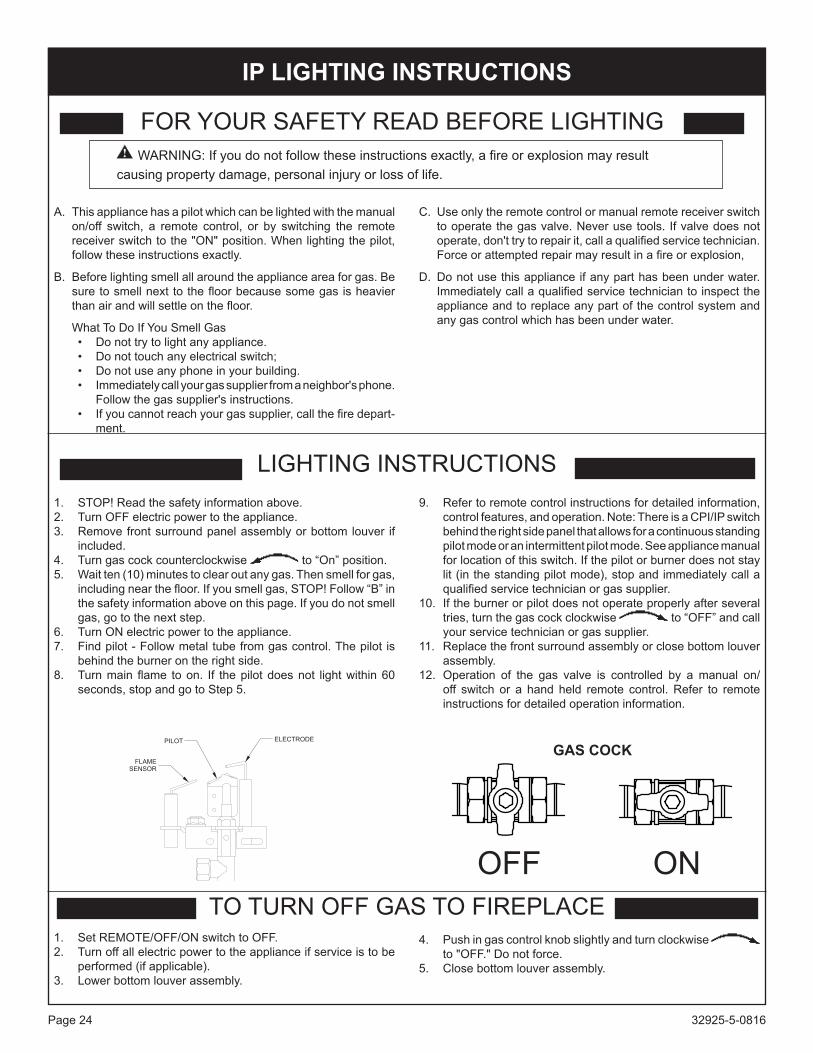
WARNING:Ifyoudonotfollowtheseinstructionsexactly,afireorexplosionmayresultcausingpropertydamage,personalinjuryorlossoflife.
32925-5-0816Page 24
TO TURN OFF GAS TO FIREPLACE
1. STOP!Readthesafetyinformationabove.2. Turn OFF electric power to the appliance.3. Removefrontsurroundpanelassemblyorbottomlouver if
included.4. Turngascockcounterclockwise to “On” position.5. Wait ten (10) minutes to clear out any gas. Then smell for gas,
includingnearthefloor.Ifyousmellgas,STOP!Follow“B”inthesafetyinformationaboveonthispage.Ifyoudonotsmellgas, go to the next step.
6. Turn ON electric power to the appliance.7. Findpilot-Followmetaltubefromgascontrol.Thepilot is
behindtheburnerontherightside.8. Turnmainflame toon. If thepilotdoesnot lightwithin60
seconds, stop and go to Step 5.
9. Refer to remote control instructions for detailed information, control features, and operation. Note: There is a CPI/IP switch behindtherightsidepanelthatallowsforacontinuousstandingpilot mode or an intermittent pilot mode. See appliance manual forlocationofthisswitch.Ifthepilotorburnerdoesnotstaylit (in the standing pilot mode), stop and immediately call a qualifiedservicetechnicianorgassupplier.
10. Iftheburnerorpilotdoesnotoperateproperlyafterseveraltries,turnthegascockclockwise to “OFF” and call your service technician or gas supplier.
11. Replacethefrontsurroundassemblyorclosebottomlouverassembly.
12. Operation of the gas valve is controlled by a manual on/off switch or a hand held remote control. Refer to remote instructions for detailed operation information.
FOR YOUR SAFETY READ BEFORE LIGHTINGWARNING:Ifyoudonotfollowtheseinstructionsexactly,afireorexplosionmayresult
causing property damage, personal injury or loss of life.
A.Thisappliancehasapilotwhichcanbelightedwiththemanualon/off switch, a remote control, or by switching the remotereceiverswitchtothe"ON"position.Whenlightingthepilot,follow these instructions exactly.
B. Before lighting smell all around the appliance area for gas. Be suretosmellnexttothefloorbecausesomegasisheavierthanairandwillsettleonthefloor.
What To Do If You Smell Gas• Donottrytolightanyappliance.• Donottouchanyelectricalswitch;• Donotuseanyphoneinyourbuilding.• Immediatelycallyourgassupplierfromaneighbor'sphone.
Follow the gas supplier's instructions.• Ifyoucannotreachyourgassupplier,callthefiredepart-
ment.
C. Use only the remote control or manual remote receiver switch to operate the gas valve. Never use tools. If valve does not operate,don'ttrytorepairit,callaqualifiedservicetechnician.Forceorattemptedrepairmayresultinafireorexplosion,
D.Donotusethisapplianceifanyparthasbeenunderwater.Immediatelycallaqualifiedservicetechniciantoinspecttheappliance and to replace any part of the control system and anygascontrolwhichhasbeenunderwater.
LIGHTING INSTRUCTIONS
1. Set REMOTE/OFF/ON switch to OFF.2. Turnoffallelectricpowertotheapplianceifserviceistobe
performed(ifapplicable).3. Lowerbottomlouverassembly.
4. Pushingascontrolknobslightlyandturnclockwise to"OFF."Donotforce.
5. Closebottomlouverassembly.
Ip LIGHTING INSTRUCTIONS
OFF ON
GASCoCKPILOT ELECTRODE
FLAME
SENSOR

32925-5-0816 Page 25
Figures 38 and 40 showacorrectpilotflamepattern.Thecorrectflamewillbeblueandwillextendbeyondthethermocouple.Theflamewill surround the thermocouple justbelow the tip.Aslightyellowflamemayoccurwherethepilotflameandmainburnerflamemeet. Figures 39 and 41showan incorrectpilotflamepattern.Theincorrectpilotflameisnottouchingthethermocouple.Thiswillcause the thermocouple to cool. When the thermocouple cools, the heater will shut down.
THERMOPILE PILOT
THERMOCOUPLE
(LPG)
THERMOCOUPLE
(NATURAL)
CorrectPilotFlamePatternforMILLIVoLTFigure 38
THERMOPILE PILOT
THERMOCOUPLE
(LPG)
THERMOCOUPLE
(NATURAL)
IncorrectPilotFlamePatternforMILLIVoLTFigure 39
Ifpilotflamepatternisincorrect,asshownin Figure 39:• SeeMillivoltTroubleshooting,page30.
pILOT FLAME CHARACTERISTICS
PILOT
SENSOR
IGNITOR
CorrectPilotFlamePatternforIPFigure 40
PILOT
SENSOR
IGNITOR
IncorrectPilotFlamePatternforIPFigure 41
Ifpilotflamepatternisincorrect,asshowninFigure 41:• SeeIPTroubleshooting,pages38-40.
Flamesfromthepilot(frontcenterofburner)aswellasthemainflameshouldbevisuallycheckedasthefireplaceisinstalled.Innormaloperationat fullrateafter10to15minutes,theflameappearanceshouldbesetsofyellowflames.Notice:Allflameswillberandombydesign,flameheightwillgoup and down.Avoidanydraftsthatalterburnerflamepatterns.Donotallowfanstoblowdirectlyintofireplace.Donotplaceablowerinsidetheburnerareaofthefirebox.Ceilingfansmaycreatedraftsthatalterflamepatterns.Sootingandimproperburningwillresult.
Duringmanufacturing,fabricatingandshipping,variouscomponentsofthisappliancearetreatedwithcertainoils,filmsorbondingagents.Thesechemicalsarenotharmful,butmayproduceannoyingsmokeandsmellsastheyareburnedoffduringtheinitialoperationoftheappliance,possiblycausingheadachesoreyeorlungirritation.Thisis a normal and temporary occurrence.Theinitialbreak-inoperationshouldlast2-3hourswiththeburnerat thehighest setting.Providemaximumventilationby openingwindows or doors to allow odors to dissipate. Any odors remaining after this initial break-inwill be slight andwill disappear withcontinued use.
Oncethebreakinoperationhasbeencompleted,adjusttheheaterto the desired output and then replace the surround.
OpERATION INSTRUCTIONS/FLAME AppEARANCE

32925-5-0816Page 26
Labelallwirespriortodisconnectionwhenservicingcontrols.Wiringerrors can cause improper and dangerous operation. Verify proper operation after servicing.Millivoltthermopileisselfpowered,gasvalvedoesnotrequire110volts. Maximum length of 20 feet of 16 AWG to conductor wires is tobeusedwithalloptionalswitches.Check750MillivoltSystemoperationMillivoltsystemandallindividualcomponentsmaybecheckedwitha millivolt meter 0-1000 MV range. The thermopile reading needs tobebetween325and400millivolts.
RemoteReceiverUse the following steps to place the remote receiver adjacent to the gas valve.Attention: The remote receiver bracket is not used in thisinstallation.1. Theremotereceivercannotbeplacedbesidethegasvalve
andburnerassembly.2. Whenfacingtheappliance,theremotereceivermustbeplaced
to the left of the gas valve.Refer to remote control installation and operating instructions for more details on remote control.
Figure 42
H N
REMOTE CONTROL RECEIVER/
THERMOSTAT/CONTROLE E
DISTANCE DU RECEPTEUR
GAS VALVE
VALVE DE GAZ
(OPTIONAL) REMOTE/OFF/ON SWITCH
A DISTANCE/OUVERT/
FERME INTERRUPTEUR (FACULATIVE)
IF ANY OF THE ORIGINAL WIRE
AS SUPPLIED WITH THIS UNIT
MUST BE REPLACED, IT MUST BE
REPLACED WITH NUMBER 18, 150 C
WIRE OR ITS EQUIVALENT.
o
SI UN DES FILS ELECTRIQUES
ORIGINAUX, VENANT DU FABRICANT
AVEC CETTE UNITE, DOIT ETRE
REMPLACE, VOUS DEVEZ LE
REMPLACER AVEC UN FIL
ELECTRIQUE DE NUMERO 18,
150 C DU L’EQUIVALENT.o
WIRING DIAGRAM
REMOTE CONTROL RECEIVER
(FACULTATIVE) CONTROLE E DISTANCE
DU RECEPTEUR
(OPTIONAL) WALL SWITCH
INTERRUPTEUR MURAL
(FACULTATIVE)
(OPTIONAL) THERMOSTAT
(FACULATIVE) THERMOSTAT
GAS VALVE
THERMOCOUPLE
(NATURAL)
THERMOCOUPLE
(LPG)
PILOT
VEILLEUSE
THERMOPILE
PRESSURE TAP
MILLIvOLT WIRING

32925-5-0816 Page 27
FRBC - MILLIvOLT CONTROL SYSTEM
INSTALLATION AND OpERATING INSTRUCTIONS
IF YOU CANNOT READ OR UNDERSTAND THESE INSTALLATION INSTRUCTIONS DO NOT ATTEMpT TO INSTALL OR OpERATE
INTRODUCTIONThis remote control system was developed to provide safe, reli-able,anduser-friendlyremotecontrolsystemforgasheatingap-pliances.Thesystemcanbeoperatedmanually fromthetransmitter.Thesystem operates on one of 255 security codes that are pro-grammed into the transmitter at the factory.Thetransmitteroperatesona12Vbattery(included)madespe-cificallyforremotecontrolsandelectroniclighters.Installthe12Vbatterysuppliedwiththeunitintothebatterycompartment.
TRANSMITTER
Figure 43Alwaysusealkalinebatteries.Theyperformbetterandlastlonger.ThetransmitterhasONandOFFfunctionsthatareactivatedbypressingeitherbuttononthefaceofthetransmitter.Whenabut-ton on the transmitter is pressed, a signal light on the transmitter illuminatesbrieflytoverifythatasignalhasbeensent.Uponinitialuse, theremay be a delay of three seconds before the remotereceiverwillrespondtothetransmitter.Thisispartofthesystem’sdesign.Ifthesignallightdoesnotilluminate,checkthepositionofthetransmitter’sbattery.
REMOTE RECEIvER
Figure 44The remote receiver operates on 4AA-size 1.5Vbatteries. It isrecommended thatALKALINE batteries be used for longer bat-tery life and maximum microprocessor performance. IMPORTANT: Neworfullychargedbatteriesareessentialforproperoperationofthe remote receiver.
The remote receiver houses the microprocessor that responds to commands from the transmitter to control system operation. The remote receiver has a 3-position slide switch for selecting the MODE of operation: ON/REMOTE/OFF
• WiththeslideswitchintheONposition(towardtheLEARNbutton), the system will remain on until the slide switch isplaced in the OFF or REMOTE position.
• WiththeslideswitchintheREMOTEposition(centered),thesystem will only operate if the remote receiver receives com-mands from the transmitter.
• With the slide switch in the OFF position (away from theLEARNbutton),thesystemisoff.
• Itissuggestedthattheslideswitchbeplacedintheoffposition if youwillbeaway fromyourhome foranex-tendedperiodoftime.Iftheremotereceiverismountedout of children’s reach, placing the slide switch in theoFF position also functions as a safety “lock-out” bybothturningthesystemoffandrenderingtheremotere-ceiver inoperative.

32925-5-0816Page 28
FRBC - MILLIvOLT CONTROL SYSTEMINSTALLATION
WARNINGThisremotecontrolsystemmustbeinstalledexactlyasoutlinedintheseinstructions.Readallinstructionscompletelybeforeat-tempting installation. Follow instructions carefully during instal-lation.AnymodificationsoftheECSremotecontroloranyofitscomponentswillvoidthewarrantandmaybeposeafirehazard.
Do not connect any gas valve or electronic module directly to 110-120VACpower.Consult gasappliancemanufacturer’s in-structions and wiring schematics for proper placement of all wires.Allelectronicmodulesaretobewiredtomanufacturer’sspecifications.
The following wiring diagrams are for illustration purpose only. Follow instructions from manufacturer of gas valve and/or elec-tronic module for correct wiring procedures. Improper instal-lation of electric components can cause damage to electronic module, gas valve and remote receiver.
The remote receiver can be either wall-mounted in a standardplasticswitchboxorplacedonornearthefireplacehearth.Pref-erably, the remote receiver should bewall-mounted in a plasticswitchbox,asthiswillprotectitselectroniccomponentsfromboththeheatproducedbythegasapplianceandpotentialdamageorabusethatcanoccurifitisleftexposedonthehearth.PROTEC-TIONFROMEXTREMEHEAT ISVERY IMPORTANT.Likeanypieceofelectronicequipment,theremotereceivershouldbekeptaway from temperatures exceeding 130° F inside the receiver case.Batterylifeisalsosignificantlyshortenedifbatteriesareex-posed to high temperatures.MakesuretheremotereceiverswitchisintheOFFposition.Itisrecommended that 18 gauge solid or stranded wires (not included) beusedtomakeconnectionsbetweentheterminalwiringblockonthe millivolt gas valve or electronic module and the wire terminals ontheremotereceiver.Forthebestresults,use18gaugesolidorstranded wire, with no splices and measuring no longer than 20 ft.
WIRING INSTRUCTIONSAqualifiedelectricianoragastechnicianwhoisfamiliarwiththegasapplianceandgasvalvesthatwillbeoperatedbythisremoteshould install the remote control system. Incorrect wiring connec-tions WILL cause damage to the gas valve or electronic module operating the gas appliance and may also damage the remote receiver.
WIRING MILLIvOLT vALvESThe remote receiver is connected to the millivolt valve using the TH(thermostat)terminalsontheterminalblockonthemillivoltgas valve.Connect 18 gauge solid or stranded wires from the remote re-ceiver to the gas valve.
Operation of the remote receiver is similar to that of a thermostat inthatbothturnthegasvalveonandoffbasedoninputsignals.Athermostat’sinputsignalsaredifferenttemperatures.There-motereceiver’sinputsignalscomefromthetransmitter.
Connect each of the two wires leading from the TH terminals on the millivolt gas valve to either of the two wire terminals on the remote receiver. Normally it does not matter which wires go to which terminal.
Figure 45
SYSTEMCHECKMILLIvOLT vALvESLight your gas appliance following the lighting instructions that camewiththeappliance.Confirmthatthepilotflameison;itmustbeinoperationforthemaingasvalvetooperate.• Slidethe3-positionbuttonontheremotereceivertotheON
position.Themaingasflame(i.e.,thefire)shouldignite.• SlidethebuttontoOFF.Theflameshouldextinguish(the
pilotflamewillremainon).• SlidethebuttontoREMOTE(thecenterposition),thenpress
theONbuttononthetransmittertochangethesystemtoON.Themaingasflameshouldignite.

32925-5-0816 Page 29
GENERAL INFORMATIONMATCHING SECURITY CODESEachtransmittercanuseoneof255uniquesecuritycodes.ItmaybenecessarytoprogramtheremotereceivertoLEARNthesecuritycodeofthetransmitteruponinitialuse,ifbatteriesarereplaced, or if a replacement transmitter is purchased from your dealerorthefactory.Whenmatchingsecuritycodes,besureslidebuttononthereceiverisintheREMOTEposition;thecodewill NOT “LEARN” if the slide switch is in the ON or OFF posi-tion. Program the remote receiver to LEARN a new security code bypushingandreleasingthelearnbutton.Asingle"beep"willsound.Pressthe"ON"buttonontheremotecontrol,untilthree"beeps"sound.Thethree"beeps"arethesignalthatthereceiverhas learned the new code. When an existing receiver is matched to a new transmitter, the new security code will override the old one.The microprocessor that controls the security code matching pro-cedureiscontrolledbyatimingfunction.Ifyouareunsuccessfulinmatchingthesecuritycodeonthefirstattempt,wait1-2min-utesbeforetryingagain–thisdelayallowsthemicroprocessortoresetitstimercircuitry–andtryuptotwoorthreemoretimes.
BATTERY LIFELifeexpectancyofthealkalinebatteriesislongerandtheperformbetterthanotherbatteries.Checkandreplaceallbatteriesannu-ally. When the transmitter no longer operates the remote receiver fromadistanceitdidpreviously(i.e.,thetransmitter’srangehasdecreased)ortheremotereceiverdoesnotfunctionatall,thebat-teriesshouldbechecked.Itisimportantthattheremotereceiverbatteriesarefullychargedandprovidescontinuousoutputvoltageof a least 5.3 volts.The lengthof thewire between the remotereceiver and gas valve directly affects the operating performance oftheremotesystem.Thelongerthewire,themorebatterypowerisrequiredtodeliversignalsbetweentheremotereceiverandthegas valve. Recommended length is no longer than 20 feet. The transmittershouldoperatewithaslittleas5.0voltsbatterypower.
TROUBLE SHOOTINGIfyouencounterproblemswithyourfireplacesystem,theproblemmaybewiththefireplaceitselforitcouldbewiththeECSremote.Review the fireplacemanufacturer’s operationmanual tomakesureallconnectionsareproperlymade.Thenchecktheoperationof the ECS remote in the following manner:• MakesurethebatteriesarecorrectlyinstalledintheRECEIV-
ER.One reversedbatterywill keep receiver fromoperatingproperly.
• CheckbatteryinTransmittertomakesurecontactsaretouch-ing(+)and(-)endsofbattery.Bendmetalcontactsinfortight-erfit.
• BesureRECEIVERandTransmitterarewithin20’-25’operat-ing range.
• KeepRECEIVERfromtemperaturesexceeding130° F. Bat-tery life shortened when ambient temperatures are above130° F.
• IfRECEIVERisinstalledintightlyenclosedmetalsurround,theoperatingdistancewillbeshortened.
RECEIvER ADJUSTMENT – RECOMMENDED ADJUSTMENT NOTE:Theslidebutton,WhiteorBlack,coverstheADJaccess hole when installed.A. To adjust at the receiver, use a small slotted screwdriver. Turn
theadjustmentscrewcounter-clockwiseabout5degreesoramaximumof1/8turn.Thisshouldcorrectthedistanceprob-lem.
B. Ifthatdoesnotcorrecttheproblem,returnadjustmentscrewtooriginalpositionandthenturnadjustmentscrewclockwise.
Thisadjustment is liketuningyourradio.Ifyoukeepturningtheadjustment screw, in either direction, you will go past the proper setting (tuning).
Figure 46
SpECIFICATIONSBATTERIES:Transmitter 12V (A23)Remote Receiver 6V-4ea.AA1.5Alkaline
FCCIDNo.’s:transmitter-K9L1002TX;Receiver - K9L3001RX
OperatingFrequency:303.875MHZ
CanadianISCIDNo.’s:transmitter-2439102728;
Receiver - 2439 102 728A
FCC REQUIREMENTSNOTE: THE MANUFACTURER IS NOT RESPONSIBLE FOR ANY RADIO OR TV INTERFERENCE CAUSED BY UNAU-THORIZED MODIFICATIONS TO THIS EQUIPMENT. SUCH MODIFICATIONSCOULDVOIDTHEUSER’SAUTHORITYTO OPERATE THE EQUIPMENT.
FRBC - MILLIvOLT CONTROL SYSTEM

32925-5-0816Page 30
Ifthegasqualityisbad,yourpilotmaynotstaylit,theburnersmayproducesootandtheheatermaybackfirewhenlit.Ifthegasqualityorpressureislow,contactyourlocalgassupplierimmediately.
1. Whenignitorbuttonispressed,thereisnosparkatoDS/pilot. a. Ignitor electrode positioned wrong - Replace pilot.b. Ignitorelectrodeisbroken-Replacepilot.c. Ignitorelectrodenotconnectedtoignitorcable-Reconnect
ignitorcable.d. Ignitorcablepinchedorwet.Keepignitorcabledry-Free
ignitorcableifpinchedbyanymetalortubing.e. Brokenignitorcable-Replaceignitorcable.f. Bad piezo ignitor - Replace piezo ignitor.
2. Applianceproducesunwantedodors.a. Applianceburningvaporsfrompaint,hairspray,glues,etc.
- Ventilate room. Stop using odor causing products while heater is running.
b. Gasleak-Locateandcorrectallleaks. 3. Applianceshutsoffduringuse.(Pilotandmainburnerare
off.)a. NotenoughfreshairisavailableforODS/pilottooperate-
Open window and/or door for ventilation.b. Lowlinepressure-Contactlocalgascompany.c. ODS/pilot is partially clogged - Clean ODS/pilot.d. Defective thermocouple - Replace pilot.
4. Appliance shuts off during use. (pilot stays on.)a. Lowlinepressure-Checklinepressuretothevalve.b. Defective thermopile - Check pilot flame, check wire
connections,outputshouldbeaminimumof325millivoltsacross. TH/TP and TP terminals with REMOTE/OFF/ON switch off.
5. GasodorevenwhencontrolknobisinoFFposition.a. Gasleak-Locateandcorrectallleaks.b. Controlvalvedefective-Replacecontrolvalve.
6. Whenignitorbuttonispressed,thereissparkatoDS/pilot,butnoignition.a. Gas supply turned off or manual shutoff valve closed - Turn
on gas supply or open manual shutoff valve.b. ControlknobnotinPILOTposition-Turncontrolknobto
PILOT position.c. ControlknobnotpressedinwhileinPILOTposition-Press
incontrolknobwhileinPILOTposition.d. Air in gas lines when installed - Continue holding down control
knob.Repeatignitingoperationuntilairisremoved.e. ODS/pilotisclogged-ReplaceODS/pilotassemblyorget
it serviced.f. Gas regulator setting is not correct - Replace gas
regulator.
7.oDS/pilot lightsbutflamegoesoutwhencontrol knob isreleased.a. Controlknobnot fullypressed in-Press incontrolknob
fully.b. Controlknobnotpressedinlongenough-AfterODS/pilot
lights,keepcontrolknobpressedin30seconds.c. Manual Shutoff valve not fully open - Fully open manual
shutoff valve.d. Thermocouple connection loose at control valve - Hand
tighten until snug, then tighten 1/4 turn more.e. Pilot flame not touching thermocouple, which allows
thermocoupletocool,causingpilotflametogoout.Thisproblemcouldbecausedbyeitherlowgaspressureordirtyorpartially clogged ODS/pilot - Contact local gas company.
f. Thermocouple damaged - Replace thermocouple.g. Control valve damaged - Replace control valve.
8. Burner does not light after ODS/pilot is lit.a. Burnerorificeclogged-Cleanburnerorreplacemainburner
orifice.b. Burner orifice diameter is too small - Replace burner
orifice.c. Inlet gas pressure is too low -Contact qualified service
person. 9. Ifburningatmainburnerorificeoccurs(aloud,roaring
blowtorchnoise).a. Youmustturnoffburnerassemblyandcontactaqualified
service person.b. Manifoldpressureistoolow-Contactlocalgascompany.c. Burner orifice clogged -Clean burner or replace burner
orifice.10. Heaterproducesawhistlingnoisewhenmainburneris
lit.a. TurningcontrolknobtoHIGHpositionwhenmainburneris
cold-TurncontrolknobtoLOWpositionandletwarmupfor a minute.
b. Airingasline-Operateburneruntilair isremovedfromline.Havegaslinecheckedbylocalgascompany.
c. Dirtyorpartiallycloggedburnerorifice-Cleanburnerorreplaceburnerorifice.
MILLIvOLT TROUBLESHOOTINGSYMpTOMS, pOSSIBLE CAUSES AND CORRECTIONS

32925-5-0816 Page 31
pROFLAME - Ip CONTROL SYSTEMTechnical Data
RemoteControlSupply voltage 4.5V(three1.5VAAAbatteries)Ambienttemperatureratings 0-50°C (32 - 122°F)
Radiofrequency 315 MHz
ReceiverSupply voltage 6.0V(four1.5VAAbatteries)Ambienttemperatureratings 0-60°C (32 - 140°F)
Radiofrequency 315MHZ
TRANSMITTER (REMOTE CONTROL WITH LCD DISpLAY)TheProflameTransmitterusesastreamlinedesignwithasimplebuttonlayoutandinformativeLCDdisplay(Figure 47).TheTransmitterispoweredby3AAAtypebatteries.AModeBut-ton isprovidedtoIndexbetweenthefeaturesandaThermostatButton is used to turn on/off or index through thermostat functions (Figures 47 and 48).
Figure47-ProflameTransmitter
Low battery alarm
Child safety lock-out
Room
Temperature
Set Point
Temperature/Level/State
Flame ON
Thermostat
OFF/ON/SMART
Transmission
Figure48-TransmitterLCDdisplay
WARNINGTHE TRANSMITTER AND RECEIVER ARE RADIO FRE-QUENCY DEVICES. PLACING THE RECEIVER IN OR NEAR METAL MAY SEVERELY REDUCE THE SIGNAL RANGE.
WARNINGFIRE HAZARD. CAN CAUSE SEvERE INJURY OR DEATH.THE RECEIVER CAUSES IGNITION OF THE APPLIANCE. THE APPLIANCE CAN TURN ON SUDDENLY. KEEP AWAY FROM THE APPLIANCE BURNER WHEN OPERATING THE REMOTE SYSTEM OR ACTIVATING MANUAL BYPASS OF THE REMOTE SYSTEM.
CAUTIONpROpERTY DAMAGE HAZARD.EXCESSIVEHEATCANCAUSEPRoPERTYDAMAGE.THE APPLIANCE CAN STAY LIT FOR MANY HOURS. TURN OFF THE APPLIANCE IF IT IS NOT GOING TO BE AT-TENDED FOR ANY LENGTH OF TIME. ALWAYS PLACE THE TRANSMITTER WHERE CHILDREN CAN NOT REACH IT.
ATTENTION• TURN“OFF”THEMAINGASSUPPLYOFTHEAPPLI-
ANCE DURING INSTALLATION OR MAINTENANCE OF THE RECEIVER.
• PLACETHERECEIVER’S3POSITIONSLIDERSWITCHIN THE “OFF” POSITION DURING INSTALLATION OR MAINTENANCE.
• TURN“OFF”MAINGASSUPPLYTOTHEAPPLIANCEPRIOR TO REMOVING OR REINSERTING THE BAT-TERIES IN THE RECEIVER.

32925-5-0816Page 32
pROFLAME - Ip CONTROL SYSTEMRECEIvERTheProflameReceiver(Figures49aand49b) connects directly to the gas valve and stepper motor with a wiring harness. The Receiverispoweredby4AAtypebatteries.TheReceiveracceptscommandsviaradiofrequencyfromtheTransmittertooperatetheapplianceinaccordancewiththeparticularProflamesystemcon-figuration.TheReceiverthreepositionsliderswitchcanbesettoone of three positions: ON (Manual Override), Remote (Remote control) or Off.
3 Positions Slider
PRG Key
Figure49a-ProflameReceiverBodyFront
14 PIN terminal
Figure49b-ProflameReceiverBodyBack
OpERATING pROCEDUREInitializingtheSystemforthefirsttimeInstall the4AAbatteries into the receiverbatterybay.Note thepolarityofbatteryandinsertintothebatterybayasindicatedonthe Battery cover (+/-). Place the 3 position slider switch in the “Remote” position.Usingtheendofapaperclip,orothersimilarobject,inserttheendofthepaperclipintotheholemarked“PRG”ontheReceiverfrontcover.TheReceiverwill “beep”three(3)timesto indicatethat itis ready to synchronize with a Transmitter. Install the 3 AAA type batteriesintheTransmitterbatterybay,locatedonthebaseoftheTransmitter.WiththebatteriesalreadyinstalledintheTransmitter,pushtheOnbutton.TheReceiverwill“beep”fourtimestoindicatetheTransmitter’scommandisacceptedandsetstotheparticularcode of that Transmitter. The system is now initialized.
TemperatureindicationDisplayWith the system in the “OFF” position, press the Thermostat But-tonandtheModeButtonatthesametime.LookattheLCDscreenontheTransmittertoverifythataCorFisvisibletotherightoftheRoom Temperature display. (Figures 50 and 51)
Figure 50 - Fahrenheit
Figure 51 - Celsius
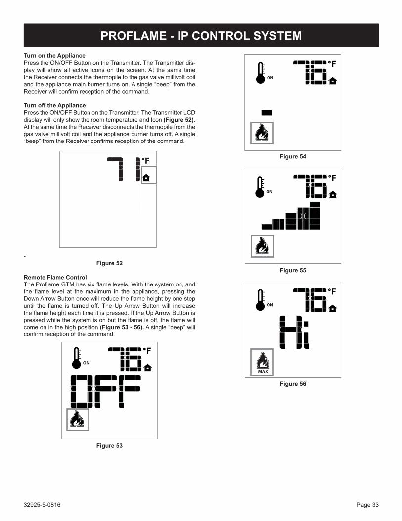
32925-5-0816 Page 33
pROFLAME - Ip CONTROL SYSTEMTurn on the AppliancePress the ON/OFF Button on the Transmitter. The Transmitter dis-play will show all active Icons on the screen. At the same time the Receiver connects the thermopile to the gas valve millivolt coil andtheappliancemainburnerturnson.Asingle“beep”fromtheReceiverwillconfirmreceptionofthecommand.
Turn off the AppliancePress the ON/OFF Button on the Transmitter. The Transmitter LCD display will only show the room temperature and Icon (Figure 52). At the same time the Receiver disconnects the thermopile from the gasvalvemillivoltcoilandtheapplianceburnerturnsoff.Asingle“beep”fromtheReceiverconfirmsreceptionofthecommand.
-Figure 52
RemoteFlameControlTheProflameGTMhassixflamelevels.Withthesystemon,andthe flame level at the maximum in the appliance, pressing theDownArrowButtononcewillreducetheflameheightbyonestepuntil the flame is turned off. TheUpArrowButtonwill increasetheflameheighteachtimeitispressed.IftheUpArrowButtonispressedwhilethesystemisonbuttheflameisoff,theflamewillcome on in the high position (Figure 53 - 56).Asingle“beep”willconfirmreceptionofthecommand.
Figure 53
Figure 54
Figure 55
Figure 56

32925-5-0816Page 34
pROFLAME - Ip CONTROL SYSTEMRooMTHERMoSTAT(Transmitteroperation)The Remote Control can operate as a room thermostat. The ther-mostatcanbesettoadesiredtemperaturetocontrolthecomfortlevel in a room.To activate this function, press the Thermostat Button (Figure 47). The LCD display on the Transmitter will change to show that the room thermostat is “ON” and the set temperature is now displayed (Figures57aand57b). To adjust the set temperature, press the Up or Down Arrow Buttons until the desired set temperature is displayed on the LCD screen of the Transmitter.
SET TEMPERATURE
ROOM TEMPERATURE
Figure 57a
Figure57b
SmartThermostat(Transmitteroperation)TheSmartThermostatfunctionadjuststheflameheightinaccor-dancetothedifferencebetweenthesetpointtemperatureandtheactual room temperatures. As the room temperature gets closer tothesetpointtheSmartFunctionwillmodulatetheflamedown.To activate this function, press the Thermostat Button (Figure 47) until theword "SMART"appears to the rightof the temperaturebulbgraphic(Figure 58). To adjust the set temperature, press the Up or Down arrow Buttons until the desired set point temperature is displayed on the LCD screen of the Transmitter (Figure 59).
Figure 58
Figure 59

32925-5-0816 Page 35
pROFLAME - Ip CONTROL SYSTEMBUTToNLoCKThisfunctionwilllockthebuttonstoavoidunsupervisedoperation.To activate this function, press the MODE and the UP Arrow But-ton at the same time (Figure 60).To de-activate this function, press the MODE and the UP Arrow Button at the same time.
Figure 60
LOW BATTERY pOWER DETECTIONTransmitterThelifespanoftheremotecontrolbatteriesdependsonvariousfactors: quality of the batteries used, the number of ignitions oftheappliance,thenumberofchangestotheroomthermostatsetpoint, etc.WhentheTransmitterbatteriesarelow,aBatteryIconwillappearon the LCD display of the Transmitter (Figure 61)beforeallbat-terypower is lost.Whenthebatteriesarereplacedthis Iconwilldisappear.
Figure 61
ReceiverThelifespanoftheReceiverbatteriesdependsonvariousfactors:qualityofthebatteriesused,thenumberofignitionsoftheappli-ance,thenumberofchangestotheroomthermostatsetpoint,etc.When theReceiverbatteriesare low,No “beep”will beemittedfrom the Receiver when it receives an On/Off command from the Transmitter.ThisisanalertforalowbatteryconditionfortheRe-ceiver.Whenthebatteriesarereplacedthe“beep”willbeemittedfrom the Receiver when the ON/OFF Button is pressed (See Ini-tialization of The System).
MANUAL BYpASS OF THE REMOTE SYSTEMIfthebatteriesoftheReceiverorTransmitterarelowordepleted,theappliancecanbeturnedonmanuallybyslidingthethreeposi-tion slider switch on the Receiver to the ON position.Thiswillbypasstheremotecontrolfeatureofthesystemandtheappliancemainburnerwillcomeonifthegasvalveisinthe“On”position.

32925-5-0816Page 36
Ip OpERATING INSTRUCTIONS5.25 vDC ELECTRONIC CONTROL vALvE
Theelectroniccontrolvalvesystemincludestheabilitytoswitchthe pilot from a standing pilot mode to an intermittent pilot mode.
• Ip Mode - In the Intermittent Pilot mode, when the unit is turnedON,itwillcausesparktothepilot,lightthepilot,thenallowtheburnertolight.WhentheunitisturnedtoOFF,boththeburnerandpilotwillbeOFF.
• CpI Mode - In the Continuous Pilot mode, the pilot re-mainsONcontinuouslyevenwhentheburneristurnedOFF.
NOTE:Asmalltoggleswitchislocatedonabracketthatisusedto switch from IP (upward position) to the CPI (downward position). See Figure 62.
When the unit is turned to ON, the electrical current will energize asparktothepilotigniter.Oncethepilotsensorheatsup(afterafewseconds),thevalvewillbeenergized,allowinggastoflowtotheburner.
1. Follow the SAFETY and LIGHTING INSTRUCTIONS for In-termittentPilotcontrols found in thismanual,andon labelsfound in the control compartment located in the lower cavity of the appliance.
2. During the operating season (or in power outage periods), it is recommended that the pilot remain in the CPI (standing pilot mode) to reduce cold start issues, and/or conserve batterybackuppowerduringapoweroutage.
3. The gas valve has inlet and outlet pressure taps as shown in Figure 62.Refertopage12forgaspressurerequirements.
DFC
ELECTRONIC
CONTROL
MODULE
REMOTE
CONTROL
RECEIVER
AA (4)
BATTERY
BACKUP
IPI
CPI
PILOT SELECTOR SWITCH
IPI - INTERMITANT PILOT (UP)
CPI - CONTINUOUS PILOT (DOWN)
SPARK ROD
GROUND
9 PIN CONNECTOR
PILOT
SENSOR
STEPPER
MOTOR
REGULATOR
GAS VALVE
OUTLET
PRESSURE
TAP
INLET
PRESSURE
TAP
IGNITORSENSOR
PILOT
ASSEMBLY
Figure 62

32925-5-0816 Page 37
Ip WIRING
Ifanyoftheoriginalwireassuppliedwiththisunitmustbereplaced,itmustbereplacedwithequivalentgaugeandtemperaturerated wire.
Thisapplianceisonlyforusewiththetypeofgasindicatedontheratingplateandmaybeinstalledinanaftermarket,permanentlylocated,manufactured(mobile)homewherenotprohibitedbylocalcodes.Thisapplianceisnotconvertibleforusewithothergases.
WARNING: Improper installation, adjustment, alteration, service or maintenance can cause property damage, personal injury or loss oflife.Installationandservicemustbeperformedbyaqualifiedinstaller,serviceagencyorthegassupplier.
Figure 63
The wire connections in Figure 63 are not used.

32925-5-0816Page 38
Ip TROUBLESHOOTINGBriefDescriptionoftheComponentsThe Digital Fireplace Control (DFC) is an automatic gas ignition systembasedonasinglemicro-controllercore.Thiscontrolman-agesall functionsrelatedto ignition,flamesensingandsupervi-sion for atmospheric applications. TheDFCcanbesettoprovidecontinuousorintermittentignitioncontrolsequencesandflamemonitoringwithsafetyshutdownincase of failure.TheDFCissetupasastandalone(ACpoweredsystemwithbat-terybackup.SeeIPLightingInstructionsonpage24andWiringDiagram on page 37.
TroubleshootingBefore proceedingwith the procedures in the following trouble-shooting table, verify that the power supply (AC/DCadapter) ispresentandthatthebatteriesinsidethereceiverand/oroptionalbatterypackarefreshandinstalledwithcorrectpolarity.Makesureall theconnectionsbetween thewireharnessesandsystem components are proper and positive.Verifythatthestaticinletpressuremeetsthemanufacturer’srec-ommended inlet pressure. If necessary adjust the line pressure regulator.Iftherecommendedactionsforthefollowingtroubleshootingchartdonothelptoaddresstheproblemconsiderreplacingwiringhar-nesses.
WARNINGAnyactionsperformedonthegasvalvemustbeperformedinaccordancewiththis instructionmanual.Likewise,anyactionsperformedontheDFCorothersystemcomponentsmustbedoneinaccordancewiththeindividualcomponentinstructions. Replacementofcomponentsmustbeperformedinaccor-dancewiththisinstructionsmanual.

32925-5-0816 Page 39
Ip TROUBLESHOOTING1
If the DFC giving signal lock out:
The board should be unlocked to
reinitiate a pilot flame ignition (for
the correct unlock sequence refer
to the DFC Use and Installation
Instructions).
Is the DFC board in
lock out?
1. Verify the electrical connections’ integrity and
make sure they are in accordance with the relevant
system wiring diagram. If necessary replace the
wire harness.
2. Replace the DFC board.
Was observed spark
at the Pilot Hood
before the DFC
board locked out?
1. Check the spark electrode positioning - adjust
as necessary.
2. Replace the pilot assembly.
3. Verify the electrical connections’ integrity and
make sure they are in accordance with the
relevant system wiring diagram. If necessary
replace the wire harness.
4. Replace the DFC board.
1. Verify the electrical connections’ integrity and
make sure they are in accordance with the
relevant system wiring diagram. If necessary
replace the wire harness.
2. If pilot flow adjuster screw is not sealed:
Check if pilot flow adjust screw is set correctly in
accordance with the appliance manufacturer
instructions. If necessary correct it.
3. Replace pilot tube or complete pilot
assembly.
4. Replace the pilot orifice with a new orifice of
correct size, and type, or replace the pilot
assembly. Under all circumstances follow the
appliance manufacturer’s service instructions.
5. Remove the provided wiring harnesses from
Ev1 of gas valve (red base), and verify voltage at
ignition between the Ev1 terminal and the ground
connection on teh valve body. If the voltage is
greater than 0 then Replace Valve. Otherwise
Replace DFC.
Spark continues
while the pilot is ON.
2
1. Replace the pilot assembly.
2. Replace the DFC board.
NO NO
YES
NO
YES
YES
YES
NO

32925-5-0816Page 40
Ip TROUBLESHOOTING2
Main burner lights
when the pilot only
should light.
Pilot holds the flame?.
Main burner ignites?
Main burner remains
ON
1. Replace DFC board.
2. Replace the gas valve.
1. Verify the pilot flame fully engulfs the tip of the sense electrode. If not replace the pilot
assembly.
2. Replace the pilot assembly.
3. Carefully clean the electrical connections of the sense cable, and the DFC board sense
cable connection.
4. Replace the sense cable, or the cable-sense electrode assembly, or the pilot assembly.
5. Verify the pilot is properly grounded.
6. Replace the pilot orifice with a new orifice of correct size, and type, or replace the pilot
assembly.
7. If pilot flow adjuster screw is not sealed, correct it.
1. Verify the electrical connections’ integrity and make sure they are in accordance with the
relevant system wiring diagram. If necessary replace the wire harness.
2. Check if the optional remote transmitter is in “thermostat” or “on” mode and verifyt there is a
call for heat (f using a thermostat remote). Adjust the setting for heat.
3. Verify that the pilot hood is properly fitted and a pilot flame is directed to properly ignite the
main appliance burner.
4. Replace the main burner orifice with a new orifice of correct size and type, or replace the
pilot assembly. Under all circumstances follow the service instructions.
5. Remove the provided wiring harnesses from EV2 of gas valve (red base), and verify voltage
at ignition between the EV1 terminal and the ground connection on the valve body.
5.1 If the voltage is greater than 0 then Replace Valve.
5.2 Or Replace DFC.
6. Check the pressure at the outlet pressure test point out according to the manufacturer’s
instruction. If not in accordance, replace the gas valve.
1. Verify the electrical connections’ integrity and make sure they are in accordance with the
relevant system wiring diagram. If necessary replace the wire harness.
2. Check the pressure at the outlet pressure test point out according the manufacturer’s
instruction. If not in accordance replace the gas valve.
3. With the system in the OFF position, connect the voltmeter between the EV2 terminal
(green base) on the valve, and the ground on the valve body.
Turn the system ON, let pilot light, and observe the following voltage sequence: once the pilot
flame is proved, the voltage on EV2 should spike to approx. 5 VdC for approx. 2 sec and then
drop to approx. 0.6 VdC continuously.
3.1 If the sequence is respected, replace the gas valve.
3.2 If the sequence is not respected, replace the DFC board.
YES
YES
YES
NO
NO
NO
NO
Main burner
modulates
properly?
1. Replace the main burner orifice with a new orifice of correct size (partial blockage possible).
Verify that the main burner flame modulates. If it does not modulate replace the gas valve.
2. Verify that the gas valve outlet pressure limits are in accordance with the manufacturer
specifications. If not replace the gas valve.
3. Verify the flame changes while rotating the HI/LO knob on the front of the gas valve. If there
is no change replace the gas valve.
FOR MANUAL HI/LO VERSION
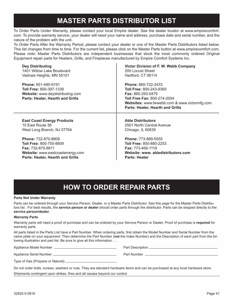
32925-5-0816 Page 41
To Order Parts Under Warranty, please contact your local Empire dealer. See the dealer locator at www.empirecomfort.com.Toprovidewarrantyservice,yourdealerwillneedyournameandaddress,purchasedateandserialnumber,andthenatureoftheproblemwiththeunit.ToOrderPartsAftertheWarrantyPeriod,pleasecontactyourdealeroroneoftheMasterPartsDistributorslistedbelow.Thislistchangesfromtimetotime.Forthecurrentlist,pleaseclickontheMasterPartsbuttonatwww.empirecomfort.com.Please note: Master Parts Distributors are independent businesses that stock the most commonly ordered OriginalEquipmentrepairpartsforHeaters,Grills,andFireplacesmanufacturedbyEmpireComfortSystemsInc.
MASTER pARTS DISTRIBUTOR LIST
parts Not Under WarrantyPartscanbeorderedthroughyourServicePerson,Dealer,oraMasterPartsDistributor.SeethispagefortheMasterPartsDistribu-torslist.Forbestresults,theservice person or dealershouldorderpartsthroughthedistributor.Partscanbeshippeddirectlytotheservice person/dealer.Warranty partsWarrantypartswillneedaproofofpurchaseandcanbeorderedbyyourServicePersonorDealer.Proofofpurchaseisrequired for warranty parts.AllpartslistedinthePartsListhaveaPartNumber.Whenorderingparts,firstobtaintheModelNumberandSerialNumberfromthenameplateonyourequipment.ThendeterminethePartNumber(nottheIndexNumber)andtheDescriptionofeachpartfromthefol-lowing illustration and part list. Be sure to give all this information . . .
ApplianceModelNumber Part Description
ApplianceSerialNumber PartNumber
Type of Gas (Propane or Natural)
Donotorderbolts,screws,washersornuts.Theyarestandardhardwareitemsandcanbepurchasedatanylocalhardwarestore.Shipmentscontingentuponstrikes,firesandallcausesbeyondourcontrol.
HOW TO ORDER REpAIR pARTS
DeyDistributing1401WillowLakeBoulevardVadnais Heights, MN 55101
phone: 651-490-9191Toll Free: 800-397-1339Website:www.deydistributing.comparts: Heater, Hearth and Grills
VictorDivisionofF.W.WebbCompany200 Locust StreetHartford, CT 06114
phone: 860-722-2433Toll Free: 800-243-9360Fax:860-293-0479TollFreeFax: 800-274-2004Websites:www.fwwebb.com&www.victormfg.comparts: Heater, Hearth and Grills
East Coast Energy products10 East Route 36West Long Branch, NJ 07764
phone: 732-870-8809Toll Free: 800-755-8809Fax:732-870-8811Website:www.eastcoastenergy.comparts: Heater, Hearth and Grills
AbleDistributors2501 North Central AvenueChicago, IL 60639
phone: 773-889-5555Toll Free: 800-880-2253Fax: 773-466-1118Website:www.abledistributors.comparts: Heater

32925-5-0816Page 42
VFLL48SP(3,9)EXPLoDEDVIEW
31
31
30
1
4
7
6
12 11 10
18
8
5
24
9
13
14
1920 15
17
16
MILLIVOLT VALVE SYSTEM
2627
2425
23
13
9
22
14
17
16 15
32
29
28
IP VALVE SYSTEM
4
30
2
3
2
5
6
8
18
33
34
Actual parts may vary from those shown.

32925-5-0816 Page 43
vFL(L,Z)48Sp(3,9) pARTS LISTINDEX
NO.Mv pART NO. (Sp3) DESCRIpTIONvFLL48 vFLZ48
1 32901 32901 INNER FIREBOX TOP AS-SEMBLY
2 DV612 DV612 BRACKET (USED AS GLASS RETAINER)
3 30291 30291 ACCENT LIGHT COVER PLATE
4 R11746 R11746 GLASS
5 32914 33362 BURNER COVER ASSEM-BLY
6 32908 33364 BURNER BOX BACK7 R11747 N/A GLASS8 R11745 R11799 BURNER, TUBE9 R3623 R3623 PILOT ASSEMBLY - LPG9 R3624 R3624 PILOT ASSEMBLY - NAT
10 P302 P302 ORIFICE 3.00mm - NAT10 P265 P265 ORIFICE #49 - LPG11 R7624 R7624 AIR SHUTTER12 P313 P313 ORIFICE HOLDER13 R3625 R3625 VALVE - LPG13 R3626 R3626 VALVE - NAT
14 29461 33373 TUBING ASSEMBLY, PILOT (LP)
15 29464 33375 TUBING ASSEMBLY, REGU-LATOR TO PILOT (NAT)
16 R7063 R7063 REGULATOR, PILOT (NAT)
17 29463 33374 TUBING ASSEMBLY, VALVE TO REGULATOR (NAT)
18 32682 33363 BURNER BOX FRONT19 R9761 R9761 PIEZO IGNITOR20 26304 26304 IGNITOR BRACKET24 FRBC FRBC TRANSMITTER & RECEIVER
30 32675 32675 BOARD, NON-COMBUSTI-BLE (2 REQ'D)
31 33014 33014 BOARD, NON-COMBUSTI-BLE (4 REQ'D)
33 33553 33553 STANDOFF SUPPORT
34 37435 37435 INNER TOP DEFLECTOR (OPTIONAL INSTALLATION)
N/S 33554 33554 HARDWARE KIT (2 REQ'D)
N/A - NOT APPLICABLE
N/S - NOT SHOWN
INDEXNO.
Ip pART NO. (Sp9) DESCRIpTIONvFLL48 vFLZ48
1 32901 32901 INNER FIREBOX TOP ASSEMBLY
2 DV612 DV612 BRACKET (USED AS GLASS RETAINER)
3 30291 30291 ACCENT LIGHT COVER PLATE
4 R11746 R11746 GLASS5 32914 33362 BURNER COVER ASSEMBLY6 32908 33364 BURNER BOX BACK7 R11747 N/A GLASS8 R11745 R11799 BURNER, TUBE9 R11327 R11327 PILOT ASSEMBLY - LPG9 R11328 R11328 PILOT ASSEMBLY - NAT10 P302 P302 ORIFICE 3.00mm - NAT10 P265 P265 ORIFICE #49 - LPG11 R7624 R7624 AIR SHUTTER12 P313 P313 ORIFICE HOLDER13 R11234 R11234 VALVE - LPG13 R11233 R11233 VALVE - NAT
14 32680 33377 TUBING ASSEMBLY, PILOT (LP)
15 32678 33376 TUBING ASSEMBLY, REGULA-TOR TO PILOT (NAT)
16 R7063 R7063 REGULATOR, PILOT (NAT)
17 29497 33374 TUBING ASSEMBLY, VALVE TO REGULATOR (NAT)
18 32690 33366 BURNER BOX FRONT - LPG18 32689 33365 BURNER BOX FRONT - NAT22 32822 32822 PILOT BRACKET - LPG22 32673 32673 PILOT BRACKET - NAT
23 R11127 R11127 CONTROL BOARD, PROFLAME
24 R11236 R11236 TRANSMITTER25 R11235 R11235 RECEIVER26 R11128 R11128 POWER ADAPTOR, 7.0 VDC
27 R11122 R11122 BATTERY HOLDER, AA WITH SNAP-ON
28 R11123 R11123 WIRE HARNESS, PROFLAME DFC
29 R11237 R11237 WIRE HARNESS, RECEIVER
30 32675 32675 BOARD, NON-COMBUSTIBLE (2 REQ'D)
31 33014 33014 BOARD, NON-COMBUSTIBLE (4 REQ'D)
32 29520 29520 HEAT SHIELD33 33553 33553 STANDOFF SUPPORT
34 37435 37435 INNER TOP DEFLECTOR (OPTIONAL INSTALLATION)
N/S 33554 33554 HARDWARE KIT (2 REQ'D)
N/A - NOT APPLICABLE
N/S - NOT SHOWN

32925-5-0816Page 44
EmpireComfortSystemsInc.warrantiesthishearthproducttobefreefromdefectsatthetimeofpurchaseandfortheperiodsspeci-fiedbelow.Hearthproductsmustbeinstalledbyaqualifiedtechnicianandmustbemaintainedandoperatedsafely,inaccordancewiththeinstructionsintheowner’smanual.EmpirewillnotwarrantyanyBoulevardfireplacethatisnotinstalledbythesellingdealerorthatdealer’sdirectcontractagents.Thiswarrantyappliestotheoriginalpurchaseronlyandisnottransferable.Allwarrantyrepairsmustbeaccomplishedbyaqualifiedgas appliance technician.
Limited Lifetime Parts Warranty with a Five-Year Limited Labor Warranty – Combustion Chamber and Heat Exchanger Ifthecombustionchamberorheatexchanger(seepartslist)failsbecauseofdefectiveworkmanshipormaterial,Empire willrepairorreplaceatEmpire’soption.Withinfiveyearsfromthedateofpurchase,Empirewillpayreasonablelaborto havethedefectivepartrepairedorreplacedatEmpire’soption.
Limited Five-Year Parts & Labor Warranty – All Other Components (Except Remote Controls, Thermostats, Accessories and Replacement Parts) Shouldanypartfailbecauseofdefectiveworkmanshipormaterialwithinfiveyearsfromthedateofpurchase,Empirewill repairorreplaceatEmpire’soption.Withinfiveyearsfromthedateofpurchase,Empirewillpayreasonablelabortohave thatdefectrepairedatEmpire’soption.
Limited One-Year Parts Warranty – Remote Controls, Thermostats, Accessories, and Parts Shouldanyremotecontrol,thermostat,accessory,orotherpartfailbecauseofdefectiveworkmanshipwithinoneyear fromthedateofpurchase,EmpirewillrepairorreplaceatEmpire’soption.
Duties Of The Owner Theappliancemustbeinstalledbyaqualifiedinstallerandoperatedinaccordancewiththeinstructionsfurnishedwith the appliance. Abillofsale,cancelledcheck,orpaymentrecordshouldbekepttoverifypurchasedateandestablishwarrantyperiod. Ready access to the appliance for service.
What Is Not Covered Damages that might result from the use, misuse, or improper installation of this appliance. Travel, diagnostic costs and freight charges on warranted parts to and from the factory. Claimsthatdonotinvolvedefectiveworkmanshipormaterials. Unauthorized service or parts replacements. Removal and reinstallation cost. Inoperableduetoimproperorlackofmaintenance.
How To Get Service Tomakeaclaimunderthiswarranty,pleasehaveyourreceiptavailableandcontactyourinstallingdealer.Providethedealer withthemodelnumber,serialnumber,typeofgas,andpurchaseverification.Theinstallingdealerisresponsibleforproviding serviceandwillcontactthefactorytoinitiateanywarrantedpartsreplacements.Empirewillmakereplacementpartsavailable at the factory. Shipping expenses are not covered. If,aftercontactingyourEmpiredealer,servicereceivedhasnotbeensatisfactory,contact:ConsumerRelationsDepartment, Empire Comfort Systems Inc., PO Box 529, Belleville, Illinois 62222, or send an e-mail to [email protected] with “ConsumerRelations”inthesubjectline.
Your Rights Under State Law Thiswarrantygivesyouspecificlegalrights,andyoumayalsohaveotherrights,whichvaryfromstatetostate.
WARRANTY
EMPIREEMPIREComfort Systems
EmpireComfortSystemsInc.Belleville, IllinoisIfyouhaveageneralquestionaboutourproducts,pleasee-mailus at [email protected]. If you have a service or repair question,pleasecontactyourdealer.
www.empirecomfort.com