Installation instructions, accessories - Park Assist, cameraftp.clubvolvo.ru/CARS DOCS AND...
35
XC90 Section Group Weight(Kg/Pounds) Year Month 3 366 1 (2.1) 2007 05 XC90 2003, XC90 2004, XC90 2005, XC90 2006, XC90 2007, XC90 2008, XC90 2008, XC90 2009, XC90 2009, XC90 2010 IMG-242200 XC90 Section Group Weight(Kg/Pounds) Year Month 3 366 1 (2.1) 2007 05 XC90 2003, XC90 2004, XC90 2005, XC90 2006, XC90 2007, XC90 2008, XC90 2008, XC90 2009, XC90 2009, XC90 2010 IMG-242200 Installation instructions, accessories - Park Assist, camera Volvo Car Corporation Göteborg, Sweden Installation instructions, accessories - Park Assist, camera Volvo Car Corporation Göteborg, Sweden © VolvoCar Corporation, 2007 Printed in Sweden 31260504 © VolvoCar Corporation, 2007 Printed in Sweden 31260504 Page 1 of 35
Transcript of Installation instructions, accessories - Park Assist, cameraftp.clubvolvo.ru/CARS DOCS AND...

XC90Section Group Weight(Kg/Pounds) Year Month
3 366 1 (2.1) 2007 05
XC90 2003, XC90 2004, XC90 2005, XC90 2006, XC90 2007, XC90 2008, XC90 2008, XC90 2009, XC90 2009, XC90 2010
IMG-242200
XC90Section Group Weight(Kg/Pounds) Year Month
3 366 1 (2.1) 2007 05
XC90 2003, XC90 2004, XC90 2005, XC90 2006, XC90 2007, XC90 2008, XC90 2008, XC90 2009, XC90 2009, XC90 2010
IMG-242200
Installation instructions, accessories - Park Assist, camera Volvo Car Corporation Göteborg, Sweden
Installation instructions, accessories - Park Assist, camera Volvo Car Corporation Göteborg, Sweden
© VolvoCar Corporation, 2007 Printed in Sweden 31260504© VolvoCar Corporation, 2007 Printed in Sweden 31260504
Page 1 of 35
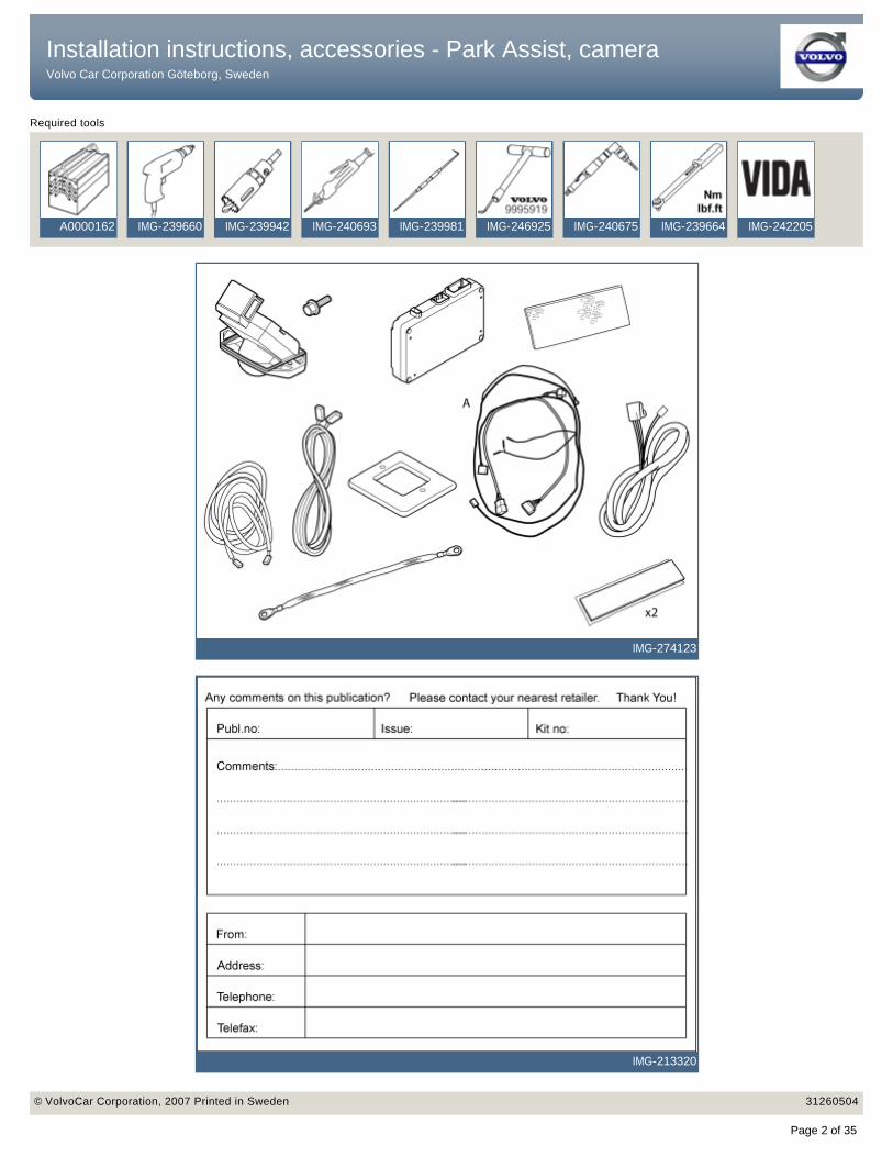
Required tools
A0000162 IMG-239660 IMG-239942 IMG-240693 IMG-239981 IMG-246925 IMG-240675 IMG-239664 IMG-242205
IMG-274123
IMG-213320
Installation instructions, accessories - Park Assist, camera Volvo Car Corporation Göteborg, Sweden
Installation instructions, accessories - Park Assist, camera Volvo Car Corporation Göteborg, Sweden
© VolvoCar Corporation, 2007 Printed in Sweden 31260504© VolvoCar Corporation, 2007 Printed in Sweden 31260504
Page 2 of 35
Installation instructions, accessories - Park Assist, camera Volvo Car Corporation Göteborg, Sweden
Installation instructions, accessories - Park Assist, camera Volvo Car Corporation Göteborg, Sweden
© VolvoCar Corporation, 2007 Printed in Sweden 31260504© VolvoCar Corporation, 2007 Printed in Sweden 31260504
Page 3 of 35
INTRODUCTION
● NOTE! Read through the entire text before carrying out any work.
● The front page gives the date of this edition and the edition it replaces
● The second page shows the tools needed for the installation and the contents of the installation kit
● The illustrations display the procedure in order of operation. The order of operation is repeated in the text section
● Cut out the text page in order to follow the illustrations and text at the same time.
Park Assist, camera
Note!
For cars with an accessory electronic module (AEM), the existing cable harness between the accessory electronic module (AEM) and the rear electronic module (REM) must be replaced (steps 51-66). The new cable harness is marked (A) in the kit image.
Installation instructions, accessories - Park Assist, camera Volvo Car Corporation Göteborg, Sweden
Installation instructions, accessories - Park Assist, camera Volvo Car Corporation Göteborg, Sweden
© VolvoCar Corporation, 2007 Printed in Sweden 31260504© VolvoCar Corporation, 2007 Printed in Sweden 31260504
Page 4 of 35

1
IMG-242207
Installing the camera
● Remove the number plate and holder.
2
IMG-242208
Installing the camera
● Apply tape to the boot lid to protect the finish.
3
IMG-242209
Installing the camera
● Position the template as illustrated.
4
IMG-242210
Installing the camera
● Make a mark according to the template's inner rectangle.
Installation instructions, accessories - Park Assist, camera Volvo Car Corporation Göteborg, Sweden
Installation instructions, accessories - Park Assist, camera Volvo Car Corporation Göteborg, Sweden
© VolvoCar Corporation, 2007 Printed in Sweden 31260504© VolvoCar Corporation, 2007 Printed in Sweden 31260504
Page 5 of 35
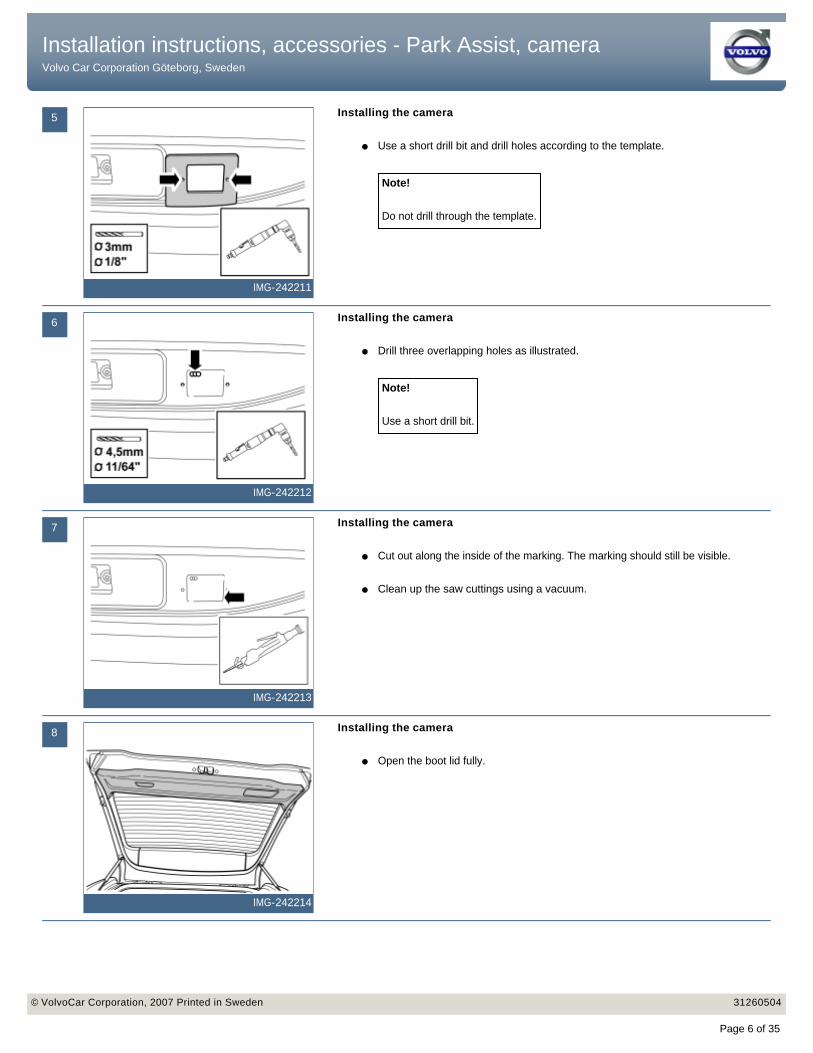
5
IMG-242211
Installing the camera
● Use a short drill bit and drill holes according to the template.
Note!
Do not drill through the template.
6
IMG-242212
Installing the camera
● Drill three overlapping holes as illustrated.
Note!
Use a short drill bit.
7
IMG-242213
Installing the camera
● Cut out along the inside of the marking. The marking should still be visible.
● Clean up the saw cuttings using a vacuum.
8
IMG-242214
Installing the camera
● Open the boot lid fully.
Installation instructions, accessories - Park Assist, camera Volvo Car Corporation Göteborg, Sweden
Installation instructions, accessories - Park Assist, camera Volvo Car Corporation Göteborg, Sweden
© VolvoCar Corporation, 2007 Printed in Sweden 31260504© VolvoCar Corporation, 2007 Printed in Sweden 31260504
Page 6 of 35
9
IMG-242215
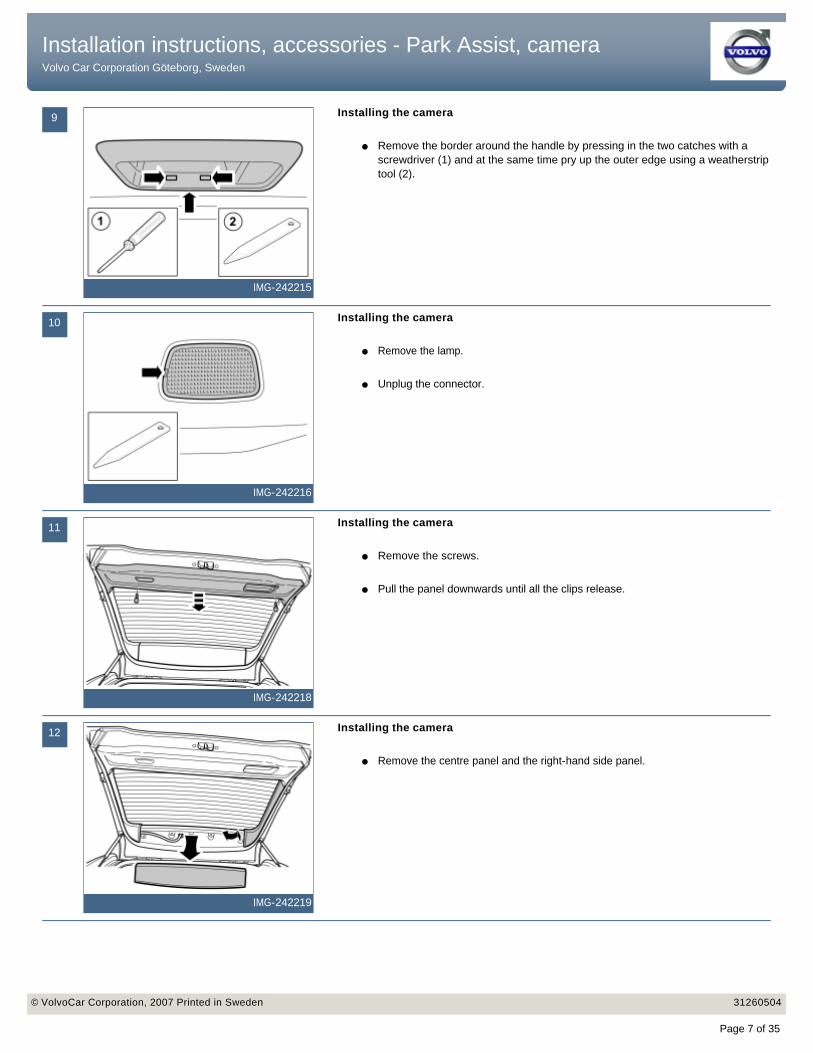
Installing the camera
● Remove the border around the handle by pressing in the two catches with a screwdriver (1) and at the same time pry up the outer edge using a weatherstrip tool (2).
10
IMG-242216
Installing the camera
● Remove the lamp.
● Unplug the connector.
11
IMG-242218
Installing the camera
● Remove the screws.
● Pull the panel downwards until all the clips release.
12
IMG-242219
Installing the camera
● Remove the centre panel and the right-hand side panel.
Installation instructions, accessories - Park Assist, camera Volvo Car Corporation Göteborg, Sweden
Installation instructions, accessories - Park Assist, camera Volvo Car Corporation Göteborg, Sweden
© VolvoCar Corporation, 2007 Printed in Sweden 31260504© VolvoCar Corporation, 2007 Printed in Sweden 31260504
Page 7 of 35
13
IMG-242220
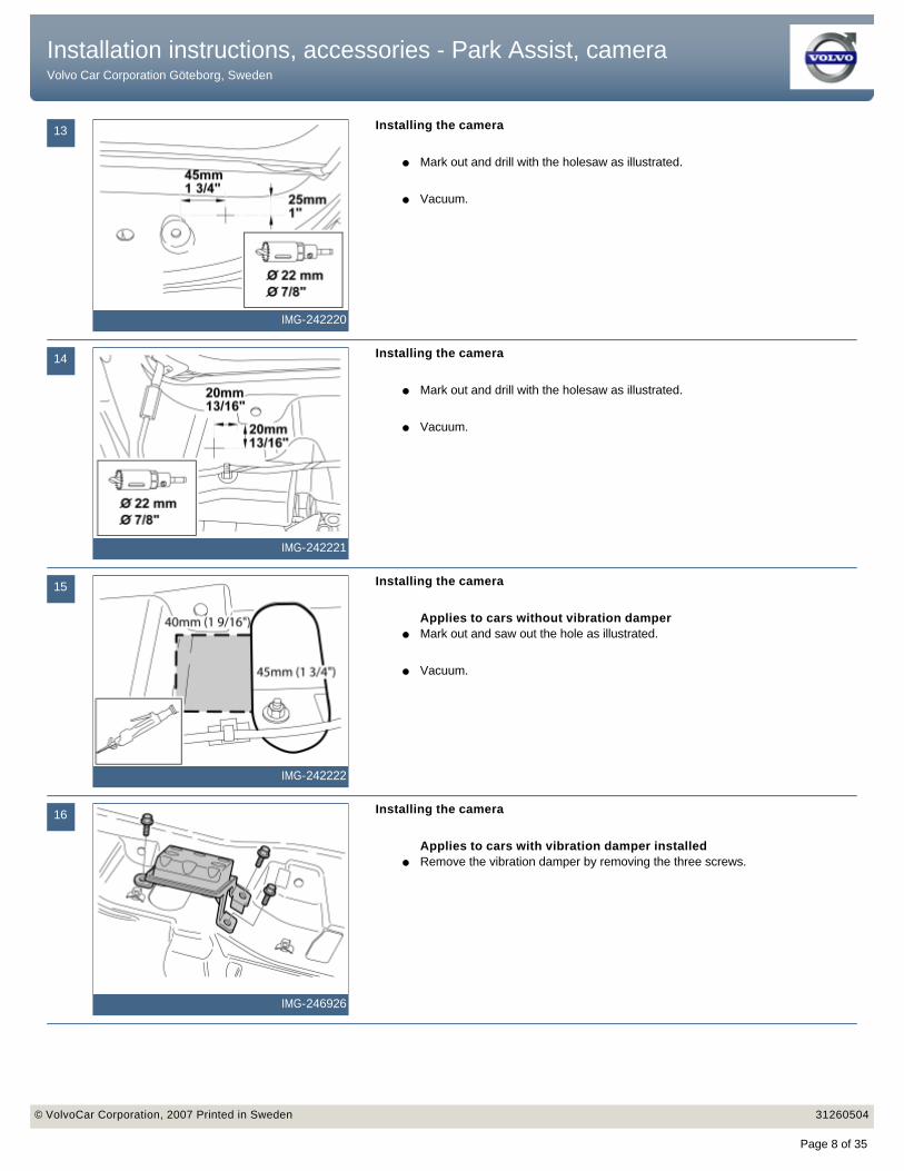
Installing the camera
● Mark out and drill with the holesaw as illustrated.
● Vacuum.
14
IMG-242221
Installing the camera
● Mark out and drill with the holesaw as illustrated.
● Vacuum.
15
IMG-242222
Installing the camera
Applies to cars without vibration damper● Mark out and saw out the hole as illustrated.
● Vacuum.
16
IMG-246926
Installing the camera
Applies to cars with vibration damper installed● Remove the vibration damper by removing the three screws.
Installation instructions, accessories - Park Assist, camera Volvo Car Corporation Göteborg, Sweden
Installation instructions, accessories - Park Assist, camera Volvo Car Corporation Göteborg, Sweden
© VolvoCar Corporation, 2007 Printed in Sweden 31260504© VolvoCar Corporation, 2007 Printed in Sweden 31260504
Page 8 of 35

17
R8504201
Installing the camera
● Remove the rear roof panel covers and the screws beneath them.
● Carefully pry off the panel at the rear edge. Use a plastic weatherstrip tool.
● Pull the rear edge of the panel downwards until the four clips on the top release.
● If the car is equipped with lighting in the panel, unplug the connector from the panel.
● Pull the panel backwards to release it.
18
IMG-242224
Installing the camera
● Disconnect the washer hose.
19
IMG-242225
Installing the camera
● Loosen the rubber pass-through and pull out the washer hose.
20
IMG-242226
Installing the camera
● Take the tail that is foam-covered about 100 mm on the cable to camera lens and thread through the hole.
Installation instructions, accessories - Park Assist, camera Volvo Car Corporation Göteborg, Sweden
Installation instructions, accessories - Park Assist, camera Volvo Car Corporation Göteborg, Sweden
© VolvoCar Corporation, 2007 Printed in Sweden 31260504© VolvoCar Corporation, 2007 Printed in Sweden 31260504
Page 9 of 35
21
IMG-242227
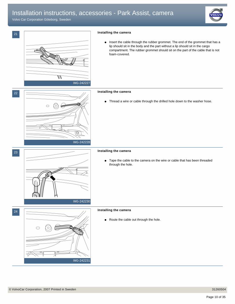
Installing the camera
● Insert the cable through the rubber grommet. The end of the grommet that has a lip should sit in the body and the part without a lip should sit in the cargo compartment. The rubber grommet should sit on the part of the cable that is not foam-covered.
22
IMG-242228
Installing the camera
● Thread a wire or cable through the drilled hole down to the washer hose.
23
IMG-242230
Installing the camera
● Tape the cable to the camera on the wire or cable that has been threaded through the hole.
24
IMG-242231
Installing the camera
● Route the cable out through the hole.
Installation instructions, accessories - Park Assist, camera Volvo Car Corporation Göteborg, Sweden
Installation instructions, accessories - Park Assist, camera Volvo Car Corporation Göteborg, Sweden
© VolvoCar Corporation, 2007 Printed in Sweden 31260504© VolvoCar Corporation, 2007 Printed in Sweden 31260504
Page 10 of 35
25
IMG-242232
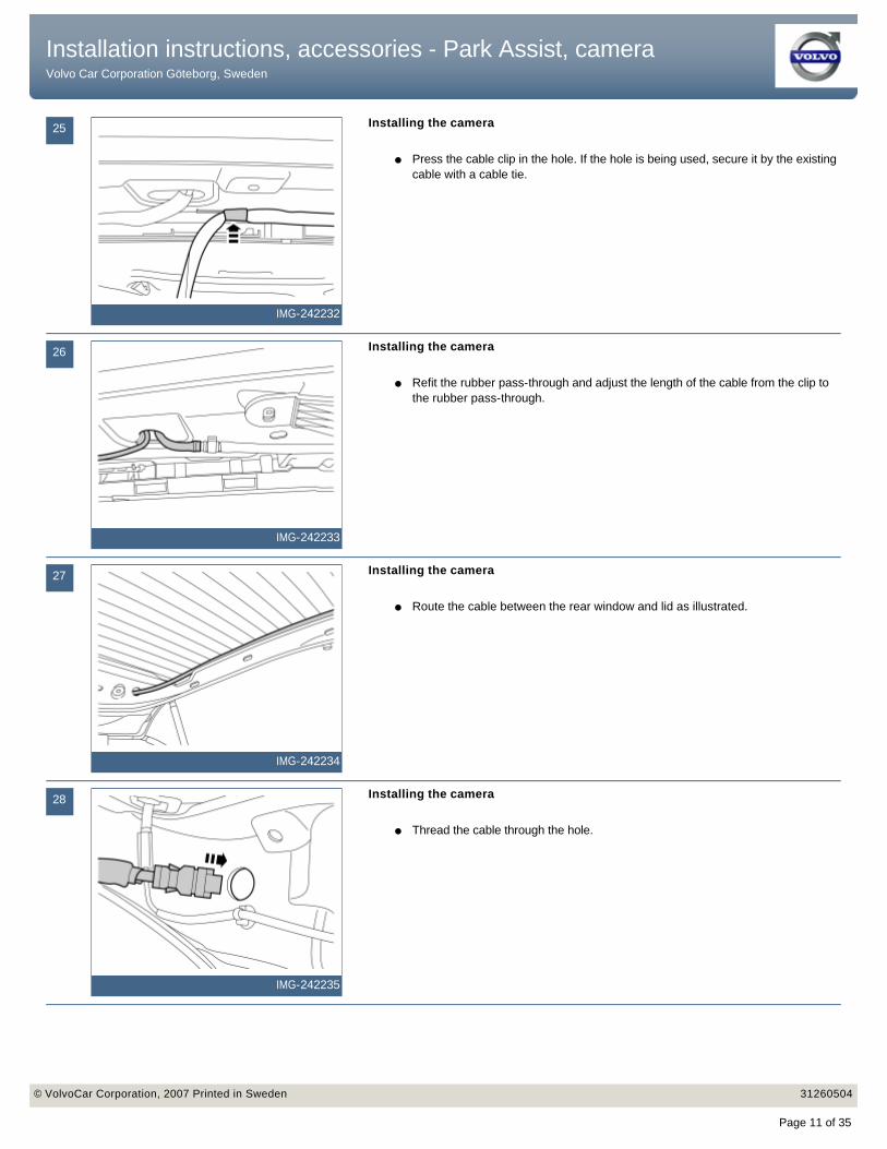
Installing the camera
● Press the cable clip in the hole. If the hole is being used, secure it by the existing cable with a cable tie.
26
IMG-242233
Installing the camera
● Refit the rubber pass-through and adjust the length of the cable from the clip to the rubber pass-through.
27
IMG-242234
Installing the camera
● Route the cable between the rear window and lid as illustrated.
28
IMG-242235
Installing the camera
● Thread the cable through the hole.
Installation instructions, accessories - Park Assist, camera Volvo Car Corporation Göteborg, Sweden
Installation instructions, accessories - Park Assist, camera Volvo Car Corporation Göteborg, Sweden
© VolvoCar Corporation, 2007 Printed in Sweden 31260504© VolvoCar Corporation, 2007 Printed in Sweden 31260504
Page 11 of 35
29
IMG-242236
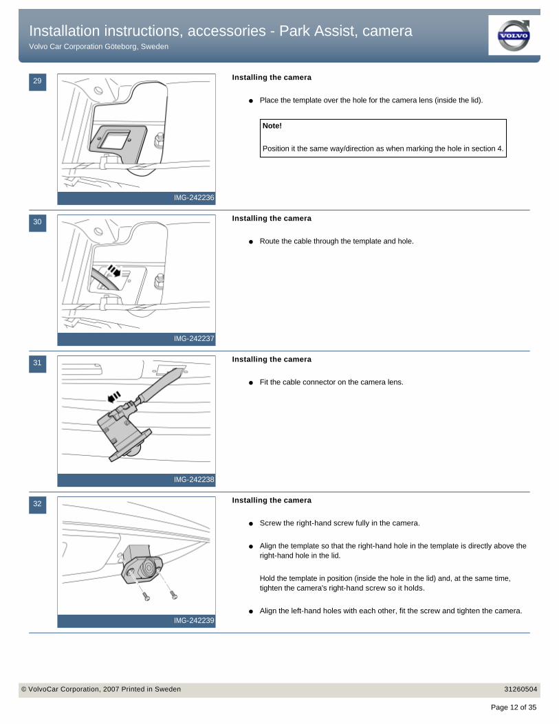
Installing the camera
● Place the template over the hole for the camera lens (inside the lid).
Note!
Position it the same way/direction as when marking the hole in section 4.
30
IMG-242237
Installing the camera
● Route the cable through the template and hole.
31
IMG-242238
Installing the camera
● Fit the cable connector on the camera lens.
32
IMG-242239
Installing the camera
● Screw the right-hand screw fully in the camera.
● Align the template so that the right-hand hole in the template is directly above the right-hand hole in the lid.
Hold the template in position (inside the hole in the lid) and, at the same time, tighten the camera's right-hand screw so it holds.
● Align the left-hand holes with each other, fit the screw and tighten the camera.
Installation instructions, accessories - Park Assist, camera Volvo Car Corporation Göteborg, Sweden
Installation instructions, accessories - Park Assist, camera Volvo Car Corporation Göteborg, Sweden
© VolvoCar Corporation, 2007 Printed in Sweden 31260504© VolvoCar Corporation, 2007 Printed in Sweden 31260504
Page 12 of 35

33
IMG-242240
Cargo compartment, preparations
Applies to cars with two rows of seats● Fold up the floor hatch (1). If the floor hatch is equipped with a grocery bag
holder, the holder is secured with a strap on both ends of the storage compartment. Detach the straps.
● Remove the storage compartment under the floor hatch.
● Remove the floor hatch by folding it almost completely closed and pulling it backwards from the mountings until it releases.
Applies to cars with three rows of seats and integrated carrier bag holder on the underside of the floor hatch
● Fold up the floor hatch (1).
● Detach the two straps on the panel under this. Lift up the rear edge of the panel, fold the floor hatch back towards the panel and lift out the floor hatch with the panel.
Applies to cars with three rows of seats without an integrated carrier bag holder
● Fold up the floor hatch (1) at the rear edge and lift it out.
34
R3100130
Cargo compartment, preparations
● Slide the driver's seat fully forwards and then fully upwards from the rear edge.
● Turn the ignition key to position 0.
● Remove the three screws in the battery holder. Lift the battery holder out.
● Remove the battery cover.
● Disconnect the battery negative lead.
35
IMG-242241
Cargo compartment, preparations
● Remove the hatch on the left-hand side of the cargo compartment.
Installation instructions, accessories - Park Assist, camera Volvo Car Corporation Göteborg, Sweden
Installation instructions, accessories - Park Assist, camera Volvo Car Corporation Göteborg, Sweden
© VolvoCar Corporation, 2007 Printed in Sweden 31260504© VolvoCar Corporation, 2007 Printed in Sweden 31260504
Page 13 of 35

36
IMG-242242
Cargo compartment, preparations
● Remove the panel.
37
R3903738
● Pull off the rubber strip on the rear edge of the door opening for the left-hand rear door opposite the left C-post panel.
● Carefully pry off the left-hand C-post panel sides at the top. Use a plastic weatherstrip tool. Then pull until the three clips on the inside release. Do not damage the headlining or the panel.
● If a headphone socket is mounted, disconnect the connector to such.
● Remove the panel by pulling upwards slightly and unhooking it from the side panel.
38
R8504123
● Carefully loosen the D-post panel. Start from the top and continue downwards until the three clips on the inside have released.
● Disconnect the connector on the D-post panel (if the car has a loudspeaker in the D-post, the connector is on the loudspeaker).
● Remove the panel by pulling upwards slightly and unhooking it from the side panel.
39
R8504313
● Fold out the load securing eyelet.
● Take a scriber or special tool part no.9995919 and insert the angled tip in the hole in the top edge of the cover.
● Twist the scriber so it grips the rear of the cover (1) and pull it loose. This should be carried out on both the front and rear load securing eyelets.
Installation instructions, accessories - Park Assist, camera Volvo Car Corporation Göteborg, Sweden
Installation instructions, accessories - Park Assist, camera Volvo Car Corporation Göteborg, Sweden
© VolvoCar Corporation, 2007 Printed in Sweden 31260504© VolvoCar Corporation, 2007 Printed in Sweden 31260504
Page 14 of 35
40
R8504315
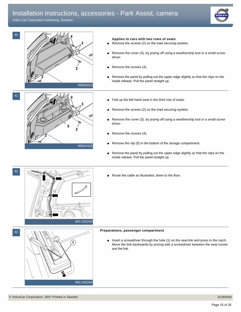
Applies to cars with two rows of seats● Remove the screws (2) on the load securing eyelets.
● Remove the cover (3), by prying off using a weatherstrip tool or a small screw driver.
● Remove the screws (4).
● Remove the panel by pulling out the upper edge slightly so that the clips on the inside release. Pull the panel straight up.
41
R8504316
● Fold up the left-hand seat in the third row of seats.
● Remove the screws (2) on the load securing eyelets.
● Remove the cover (3), by prying off using a weatherstrip tool or a small screw driver.
● Remove the screws (4).
● Remove the clip (5) in the bottom of the storage compartment.
● Remove the panel by pulling out the upper edge slightly so that the clips on the inside release. Pull the panel straight up.
42
IMG-242243
● Route the cable as illustrated, down to the floor.
43
IMG-242244
Preparations, passenger compartment
● Insert a screwdriver through the hole (1) on the seat link and press in the catch. Move the link backwards by prizing with a screwdriver between the seat runner and the link.
Installation instructions, accessories - Park Assist, camera Volvo Car Corporation Göteborg, Sweden
Installation instructions, accessories - Park Assist, camera Volvo Car Corporation Göteborg, Sweden
© VolvoCar Corporation, 2007 Printed in Sweden 31260504© VolvoCar Corporation, 2007 Printed in Sweden 31260504
Page 15 of 35

44
IMG-242245
Preparations, passenger compartment
● Carefully prise loose and remove the panel over the joint between the door sills.
45
IMG-242246
Preparations, passenger compartment
● Pull loose the sill molding on the front edge then straight up. Angle out the sill molding from the B-post panel.
46
R8504309
Preparations, passenger compartment
● Press the catch (1) in and remove the front seat link.
● Remove the screw.
47
R8504310
Preparations, passenger compartment
● Press in the catches (1) and remove the seat link as illustrated.
● Remove the screw.
Installation instructions, accessories - Park Assist, camera Volvo Car Corporation Göteborg, Sweden
Installation instructions, accessories - Park Assist, camera Volvo Car Corporation Göteborg, Sweden
© VolvoCar Corporation, 2007 Printed in Sweden 31260504© VolvoCar Corporation, 2007 Printed in Sweden 31260504
Page 16 of 35
48
IMG-242247
Preparations, passenger compartment
● Fold down the backrest.
● Remove the seat links and bolts.
● Lift out the seat.
Caution!
Exercise care when doing this so that the trim or door panels are not damaged.
49
IMG-245600
Preparations, passenger compartment
● Loosen the upper part of the sill moulding on the rear edge and loosen the seat belt from the end fitting. The belt is loosened by carefully pressing with a weatherstrip tool on the lock lug so that the seat belt releases from the end fitting.
50
IMG-242248
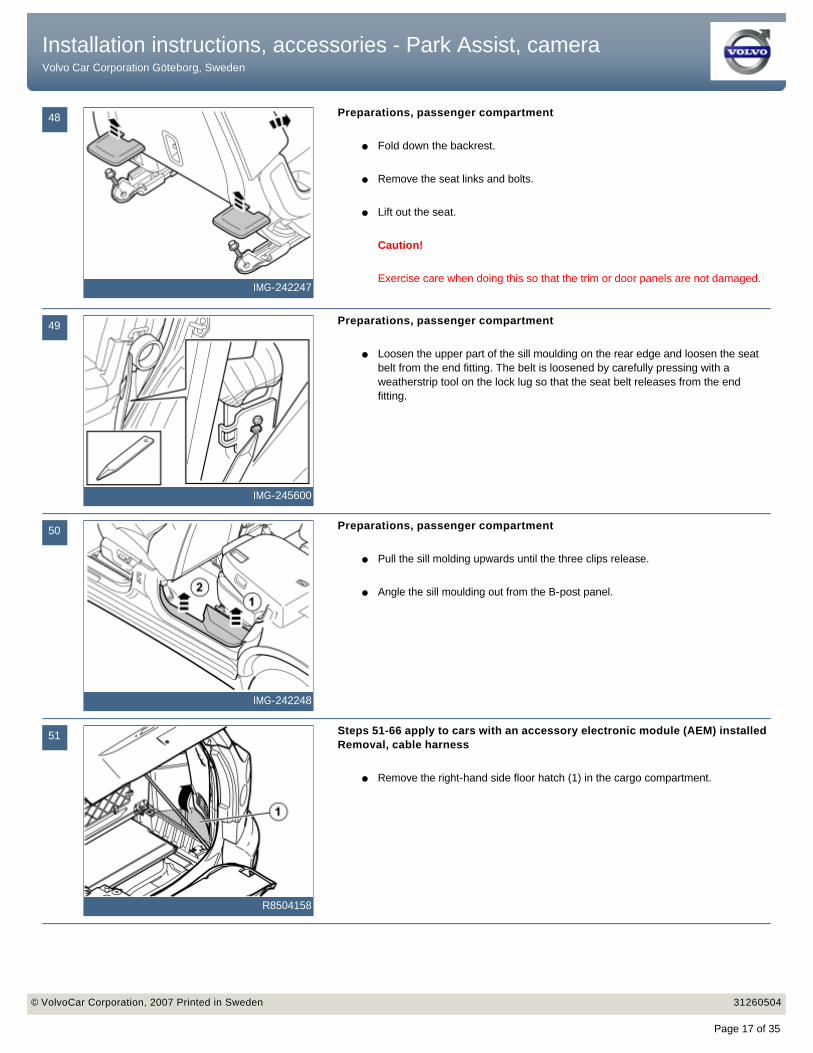
Preparations, passenger compartment
● Pull the sill molding upwards until the three clips release.
● Angle the sill moulding out from the B-post panel.
51
R8504158
Steps 51-66 apply to cars with an accessory electronic module (AEM) installed Removal, cable harness
● Remove the right-hand side floor hatch (1) in the cargo compartment.
Installation instructions, accessories - Park Assist, camera Volvo Car Corporation Göteborg, Sweden
Installation instructions, accessories - Park Assist, camera Volvo Car Corporation Göteborg, Sweden
© VolvoCar Corporation, 2007 Printed in Sweden 31260504© VolvoCar Corporation, 2007 Printed in Sweden 31260504
Page 17 of 35
52
IMG-273225
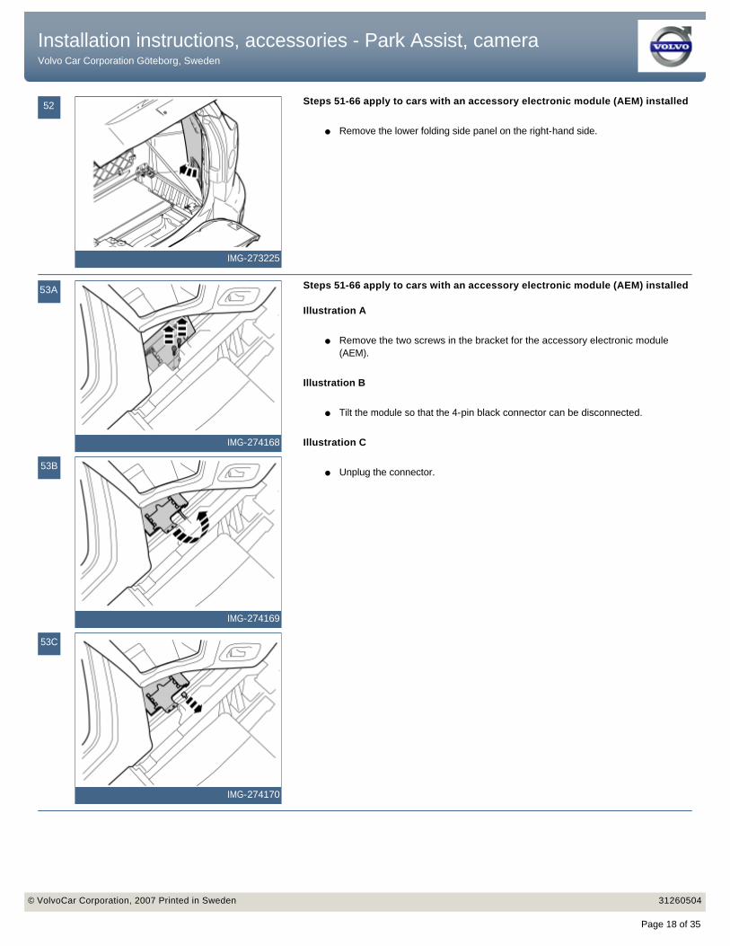
Steps 51-66 apply to cars with an accessory electronic module (AEM) installed
● Remove the lower folding side panel on the right-hand side.
53A
IMG-274168
53B
IMG-274169
53C
IMG-274170
Steps 51-66 apply to cars with an accessory electronic module (AEM) installed
Illustration A
● Remove the two screws in the bracket for the accessory electronic module (AEM).
Illustration B
● Tilt the module so that the 4-pin black connector can be disconnected.
Illustration C
● Unplug the connector.
Installation instructions, accessories - Park Assist, camera Volvo Car Corporation Göteborg, Sweden
Installation instructions, accessories - Park Assist, camera Volvo Car Corporation Göteborg, Sweden
© VolvoCar Corporation, 2007 Printed in Sweden 31260504© VolvoCar Corporation, 2007 Printed in Sweden 31260504
Page 18 of 35
54
IMG-274171
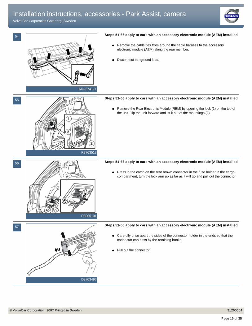
Steps 51-66 apply to cars with an accessory electronic module (AEM) installed
● Remove the cable ties from around the cable harness to the accessory electronic module (AEM) along the rear member.
● Disconnect the ground lead.
55
R3703513
Steps 51-66 apply to cars with an accessory electronic module (AEM) installed
● Remove the Rear Electronic Module (REM) by opening the lock (1) on the top of the unit. Tip the unit forward and lift it out of the mountings (2).
56
R3905101
Steps 51-66 apply to cars with an accessory electronic module (AEM) installed
● Press in the catch on the rear brown connector in the fuse holder in the cargo compartment, turn the lock arm up as far as it will go and pull out the connector.
57
D3703496
Steps 51-66 apply to cars with an accessory electronic module (AEM) installed
● Carefully prise apart the sides of the connector holder in the ends so that the connector can pass by the retaining hooks.
● Pull out the connector.
Installation instructions, accessories - Park Assist, camera Volvo Car Corporation Göteborg, Sweden
Installation instructions, accessories - Park Assist, camera Volvo Car Corporation Göteborg, Sweden
© VolvoCar Corporation, 2007 Printed in Sweden 31260504© VolvoCar Corporation, 2007 Printed in Sweden 31260504
Page 19 of 35

58
R3703512
Steps 51-66 apply to cars with an accessory electronic module (AEM) installed
● Remove the red (R) cable from terminal 22.
59
M3904942
Steps 51-66 apply to cars with an accessory electronic module (AEM) installed
● Press in the catch on the gray connector on the rear of the fuse holder in the cargo compartment. Turn the lock arm up as far as it will go and pull out the connector.
60
M3703366
Steps 51-66 apply to cars with an accessory electronic module (AEM) installed
● Carefully prise apart the sides of the connector holder in the ends so that the connector can pass by the retaining hooks.
● Pull out the connector.
61
R3703511
Steps 51-66 apply to cars with an accessory electronic module (AEM) installed
● Remove the green (GN) cable from terminal 19 and white (W) from terminal 30 in the connector.
● Remove the entire cable harness and place to one side. This will not be reused.
Installation instructions, accessories - Park Assist, camera Volvo Car Corporation Göteborg, Sweden
Installation instructions, accessories - Park Assist, camera Volvo Car Corporation Göteborg, Sweden
© VolvoCar Corporation, 2007 Printed in Sweden 31260504© VolvoCar Corporation, 2007 Printed in Sweden 31260504
Page 20 of 35

62
R3603578
Installing the cable harness
● Take the new cable harness (purchased separately), marked A in the kit image and place it behind the battery.
● Pull the cable end with black 4-pin connector through the hole in the rear edge of the right-hand cargo floor support, up to the accessory electronic module (AEM). Route the other end in a corresponding way to the fuse holder on the left-hand side.
63A
IMG-274224
63B
IMG-274225
63C
IMG-274226
Illustration A
● Connect the black 4-pin connector to the accessory electronic module (AEM).
Illustration BIllustration C
● Reinstall the module and tighten using the two screws.
Installation instructions, accessories - Park Assist, camera Volvo Car Corporation Göteborg, Sweden
Installation instructions, accessories - Park Assist, camera Volvo Car Corporation Göteborg, Sweden
© VolvoCar Corporation, 2007 Printed in Sweden 31260504© VolvoCar Corporation, 2007 Printed in Sweden 31260504
Page 21 of 35
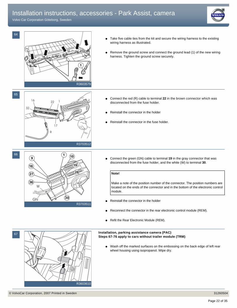
64
R3603579
● Take five cable ties from the kit and secure the wiring harness to the existing wiring harness as illustrated.
● Remove the ground screw and connect the ground lead (1) of the new wiring harness. Tighten the ground screw securely.
65
R3703512
● Connect the red (R) cable to terminal 22 in the brown connector which was disconnected from the fuse holder.
● Reinstall the connector in the holder
● Reinstall the connector in the fuse holder.
66
R3703511
● Connect the green (GN) cable to terminal 19 in the gray connector that was disconnected from the fuse holder, and the white (W) to terminal 30.
● Reinstall the connector in the holder
● Reconnect the connector in the rear electronic control module (REM).
● Refit the Rear Electronic Module (REM).
Note!
Make a note of the position number of the connector. The position numbers are located on the ends of the connector and in the bottom of the electronic control module.
67
R3603610
Installation, parking assistance camera (PAC)Steps 67-76 apply to cars without trailer module (TRM)
● Wash off the marked surfaces on the embossing on the back edge of left rear wheel housing using isopropanol. Wipe dry.
Installation instructions, accessories - Park Assist, camera Volvo Car Corporation Göteborg, Sweden
Installation instructions, accessories - Park Assist, camera Volvo Car Corporation Göteborg, Sweden
© VolvoCar Corporation, 2007 Printed in Sweden 31260504© VolvoCar Corporation, 2007 Printed in Sweden 31260504
Page 22 of 35
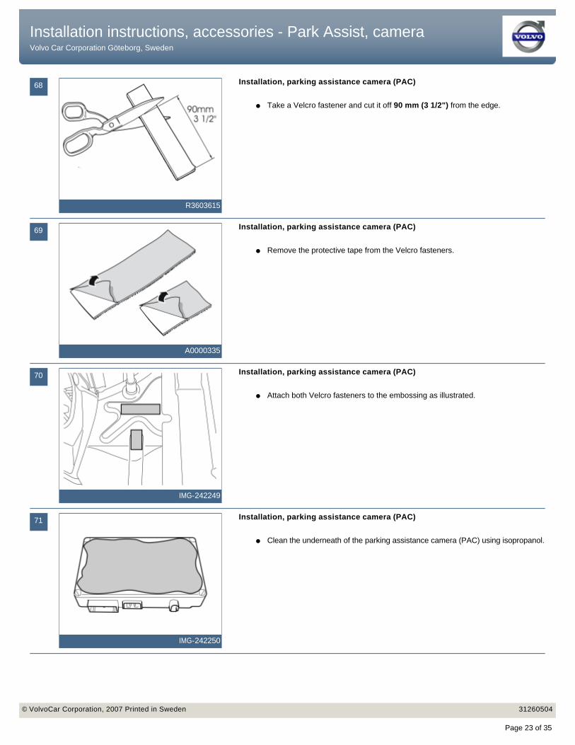
68
R3603615
Installation, parking assistance camera (PAC)
● Take a Velcro fastener and cut it off 90 mm (3 1/2") from the edge.
69
A0000335
Installation, parking assistance camera (PAC)
● Remove the protective tape from the Velcro fasteners.
70
IMG-242249
Installation, parking assistance camera (PAC)
● Attach both Velcro fasteners to the embossing as illustrated.
71
IMG-242250
Installation, parking assistance camera (PAC)
● Clean the underneath of the parking assistance camera (PAC) using isopropanol.
Installation instructions, accessories - Park Assist, camera Volvo Car Corporation Göteborg, Sweden
Installation instructions, accessories - Park Assist, camera Volvo Car Corporation Göteborg, Sweden
© VolvoCar Corporation, 2007 Printed in Sweden 31260504© VolvoCar Corporation, 2007 Printed in Sweden 31260504
Page 23 of 35

72
R3603612
Installation, parking assistance camera (PAC)
● Take a Velcro fastener and cut it off 75 mm (3) from the edge.
73
R3603616
Installation, parking assistance camera (PAC)
● Remove the protective tape from the Velcro fasteners.
74
IMG-242251
Installation, parking assistance camera (PAC)
● Secure the Velcro fasteners on the control module as illustrated.
75
IMG-242252
Installation, parking assistance camera (PAC)
● Connect the three connectors to the control module.
Installation instructions, accessories - Park Assist, camera Volvo Car Corporation Göteborg, Sweden
Installation instructions, accessories - Park Assist, camera Volvo Car Corporation Göteborg, Sweden
© VolvoCar Corporation, 2007 Printed in Sweden 31260504© VolvoCar Corporation, 2007 Printed in Sweden 31260504
Page 24 of 35

76
IMG-242253
Installation, parking assistance camera (PAC)
● Secure the control module on the newly attached Velcro fasteners. Press hard so that sits firmly.
77
IMG-242254
Installation, parking assistance camera (PAC)Steps 77-85 apply to cars with a trailer module (TRM) installed
● Clean the surfaces, as illustrated, on the trailer module (TRM) using isopropanol.
78
IMG-242255
Installation, parking assistance camera (PAC)
● Clean the underneath of the parking assistance camera (PAC) using isopropanol. Wipe dry.
79
IMG-222282
Installation, parking assistance camera (PAC)
● Remove the two Velcro fasteners from the kit and cut them in the middle.
Installation instructions, accessories - Park Assist, camera Volvo Car Corporation Göteborg, Sweden
Installation instructions, accessories - Park Assist, camera Volvo Car Corporation Göteborg, Sweden
© VolvoCar Corporation, 2007 Printed in Sweden 31260504© VolvoCar Corporation, 2007 Printed in Sweden 31260504
Page 25 of 35

80
IMG-222283
Installation, parking assistance camera (PAC)
● Press the Velcro pieces together.
81
IMG-222285
Installation, parking assistance camera (PAC)
● Remove the protective film on one side of the Velcro fasteners.
82
IMG-242256
Installation, parking assistance camera (PAC)
● Press the Velcro fasteners onto the parking assistance camera (PAC) as illustrated.
83
IMG-242257
Installation, parking assistance camera (PAC)
● Remove the protective film from the Velcro fasteners.
Installation instructions, accessories - Park Assist, camera Volvo Car Corporation Göteborg, Sweden
Installation instructions, accessories - Park Assist, camera Volvo Car Corporation Göteborg, Sweden
© VolvoCar Corporation, 2007 Printed in Sweden 31260504© VolvoCar Corporation, 2007 Printed in Sweden 31260504
Page 26 of 35
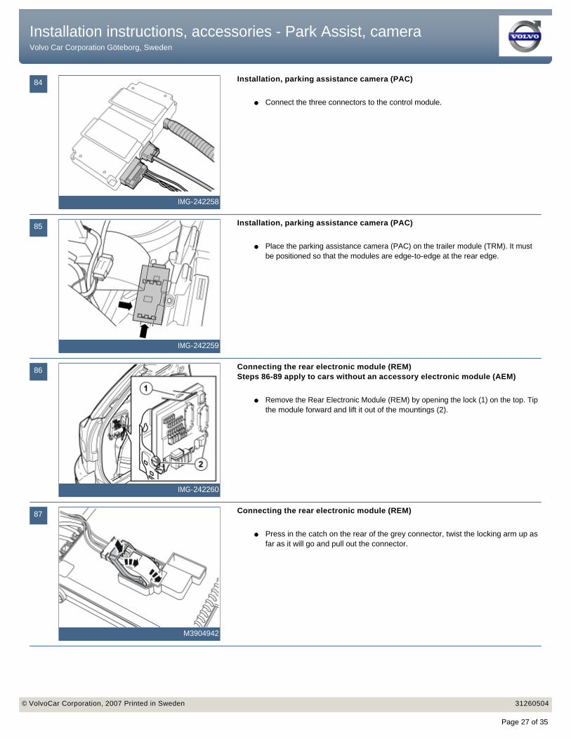
84
IMG-242258
Installation, parking assistance camera (PAC)
● Connect the three connectors to the control module.
85
IMG-242259
Installation, parking assistance camera (PAC)
● Place the parking assistance camera (PAC) on the trailer module (TRM). It must be positioned so that the modules are edge-to-edge at the rear edge.
86
IMG-242260
Connecting the rear electronic module (REM)Steps 86-89 apply to cars without an accessory electronic module (AEM)
● Remove the Rear Electronic Module (REM) by opening the lock (1) on the top. Tip the module forward and lift it out of the mountings (2).
87
M3904942
Connecting the rear electronic module (REM)
● Press in the catch on the rear of the grey connector, twist the locking arm up as far as it will go and pull out the connector.
Installation instructions, accessories - Park Assist, camera Volvo Car Corporation Göteborg, Sweden
Installation instructions, accessories - Park Assist, camera Volvo Car Corporation Göteborg, Sweden
© VolvoCar Corporation, 2007 Printed in Sweden 31260504© VolvoCar Corporation, 2007 Printed in Sweden 31260504
Page 27 of 35
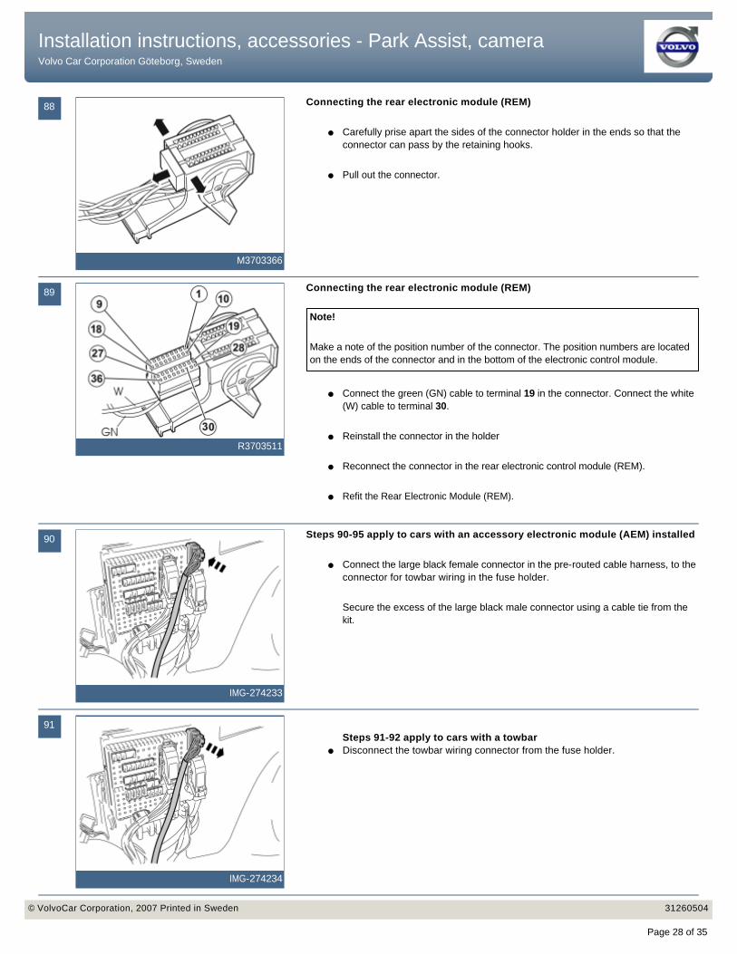
88
M3703366
Connecting the rear electronic module (REM)
● Carefully prise apart the sides of the connector holder in the ends so that the connector can pass by the retaining hooks.
● Pull out the connector.
89
R3703511
Connecting the rear electronic module (REM)
● Connect the green (GN) cable to terminal 19 in the connector. Connect the white (W) cable to terminal 30.
● Reinstall the connector in the holder
● Reconnect the connector in the rear electronic control module (REM).
● Refit the Rear Electronic Module (REM).
Note!
Make a note of the position number of the connector. The position numbers are located on the ends of the connector and in the bottom of the electronic control module.
90
IMG-274233
Steps 90-95 apply to cars with an accessory electronic module (AEM) installed
● Connect the large black female connector in the pre-routed cable harness, to the connector for towbar wiring in the fuse holder.
Secure the excess of the large black male connector using a cable tie from the kit.
91
IMG-274234
Steps 91-92 apply to cars with a towbar ● Disconnect the towbar wiring connector from the fuse holder.
Installation instructions, accessories - Park Assist, camera Volvo Car Corporation Göteborg, Sweden
Installation instructions, accessories - Park Assist, camera Volvo Car Corporation Göteborg, Sweden
© VolvoCar Corporation, 2007 Printed in Sweden 31260504© VolvoCar Corporation, 2007 Printed in Sweden 31260504
Page 28 of 35

92
IMG-274235
● Connect the large black female connector in the pre-routed cable harness to the fuse holder.
● Connect the towbar wiring connector, which was disconnected from the fuse holder to the corresponding one in the routed cable harness.
93
IMG-274236
Steps 93-95 apply to cars with a towbar wiring adapter ● Disconnect the towbar wiring adapter's connector from the fuse holder.
94
IMG-274237
● Connect the large black female connector in the pre-routed cable harness to the fuse holder.
● Connect the towbar wiring adapter's connector, which was disconnected from the fuse holder to the corresponding one in the routed cable harness.
95
IMG-274238
● Secure the loose cables and the small fuse holder using a cable tie.
Installation instructions, accessories - Park Assist, camera Volvo Car Corporation Göteborg, Sweden
Installation instructions, accessories - Park Assist, camera Volvo Car Corporation Göteborg, Sweden
© VolvoCar Corporation, 2007 Printed in Sweden 31260504© VolvoCar Corporation, 2007 Printed in Sweden 31260504
Page 29 of 35

96
IMG-242261
Connection to multimedia module (MMM)
● Route both adapter cables (5 way green and 12 way gray connector) along the molding and up to the driver's seat.
97
IMG-242262
Connection to multimedia module (MMM)
● Disconnect the two connectors on the multimedia module (MMM).
98
IMG-242263
Connection to multimedia module (MMM)
● Connect the pre-routed adapter cables to the multimedia module (MMM) and to respective disconnected connectors.
Note!
Route the new cables under the existing cables.
99
IMG-242264
Connection to multimedia module (MMM)
● Place the connectors and excess wiring in the joint under the carpet.
Installation instructions, accessories - Park Assist, camera Volvo Car Corporation Göteborg, Sweden
Installation instructions, accessories - Park Assist, camera Volvo Car Corporation Göteborg, Sweden
© VolvoCar Corporation, 2007 Printed in Sweden 31260504© VolvoCar Corporation, 2007 Printed in Sweden 31260504
Page 30 of 35
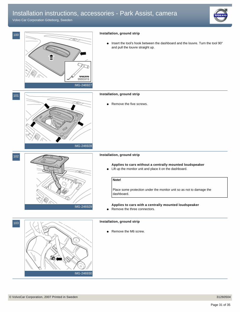
100
IMG-246927
Installation, ground strip
● Insert the tool's hook between the dashboard and the louvre. Turn the tool 90° and pull the louvre straight up.
101
IMG-246928
Installation, ground strip
● Remove the five screws.
102
IMG-246929
Installation, ground strip
Applies to cars without a centrally mounted loudspeaker● Lift up the monitor unit and place it on the dashboard.
Applies to cars with a centrally mounted loudspeaker● Remove the three connectors.
Note!
Place some protection under the monitor unit so as not to damage the dashboard.
103
IMG-246930
Installation, ground strip
● Remove the M6 screw.
Installation instructions, accessories - Park Assist, camera Volvo Car Corporation Göteborg, Sweden
Installation instructions, accessories - Park Assist, camera Volvo Car Corporation Göteborg, Sweden
© VolvoCar Corporation, 2007 Printed in Sweden 31260504© VolvoCar Corporation, 2007 Printed in Sweden 31260504
Page 31 of 35
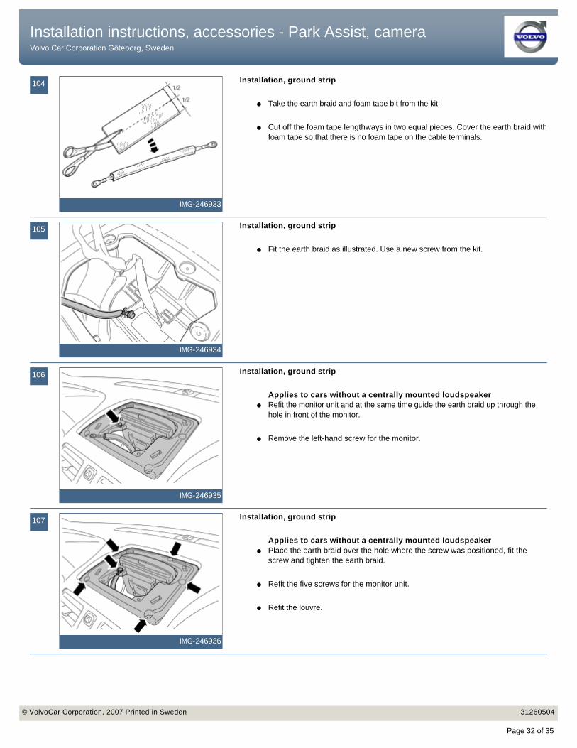
104
IMG-246933
Installation, ground strip
● Take the earth braid and foam tape bit from the kit.
● Cut off the foam tape lengthways in two equal pieces. Cover the earth braid with foam tape so that there is no foam tape on the cable terminals.
105
IMG-246934
Installation, ground strip
● Fit the earth braid as illustrated. Use a new screw from the kit.
106
IMG-246935
Installation, ground strip
Applies to cars without a centrally mounted loudspeaker● Refit the monitor unit and at the same time guide the earth braid up through the
hole in front of the monitor.
● Remove the left-hand screw for the monitor.
107
IMG-246936
Installation, ground strip
Applies to cars without a centrally mounted loudspeaker● Place the earth braid over the hole where the screw was positioned, fit the
screw and tighten the earth braid.
● Refit the five screws for the monitor unit.
● Refit the louvre.
Installation instructions, accessories - Park Assist, camera Volvo Car Corporation Göteborg, Sweden
Installation instructions, accessories - Park Assist, camera Volvo Car Corporation Göteborg, Sweden
© VolvoCar Corporation, 2007 Printed in Sweden 31260504© VolvoCar Corporation, 2007 Printed in Sweden 31260504
Page 32 of 35
108
IMG-248723
Installation, ground strip
Steps 108-113 apply to cars with a centrally mounted loudspeaker ● Remove the three screws for the monitor.
● Remove the monitor by first angling it backwards at the lower edge and then guiding it out.
109
IMG-248724
Installation, ground strip
● Locate the end by the left-hand mounting point for the monitor on the loudspeaker frame.
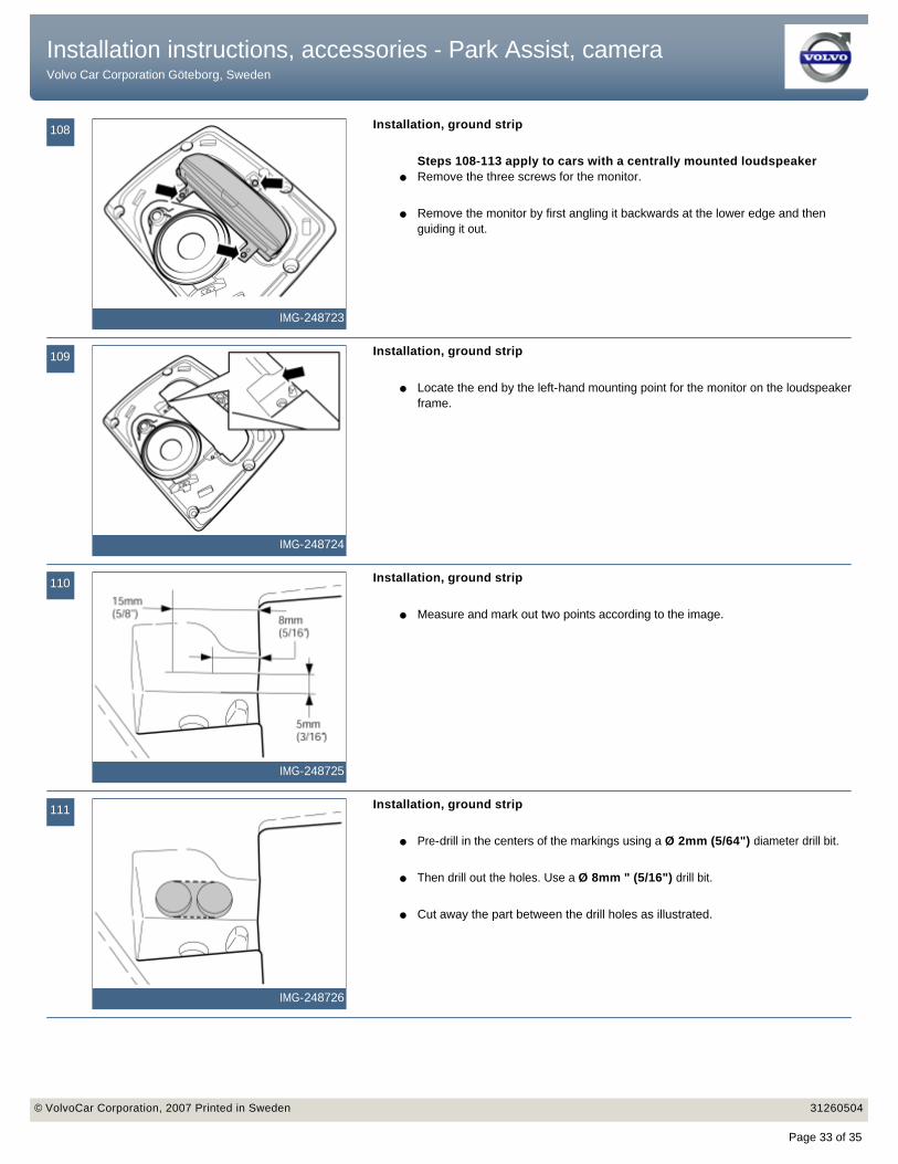
110
IMG-248725
Installation, ground strip
● Measure and mark out two points according to the image.
111
IMG-248726
Installation, ground strip
● Pre-drill in the centers of the markings using a Ø 2mm (5/64") diameter drill bit.
● Then drill out the holes. Use a Ø 8mm " (5/16") drill bit.
● Cut away the part between the drill holes as illustrated.
Installation instructions, accessories - Park Assist, camera Volvo Car Corporation Göteborg, Sweden
Installation instructions, accessories - Park Assist, camera Volvo Car Corporation Göteborg, Sweden
© VolvoCar Corporation, 2007 Printed in Sweden 31260504© VolvoCar Corporation, 2007 Printed in Sweden 31260504
Page 33 of 35
112
IMG-248727
Installation, ground strip
● Reinstall the monitor and tighten using two screws as illustrated.
113
IMG-248728
Installation, ground strip
● Take the loose end of the ground strip and thread it through the drilled holes from underneath.
● Secure the cable terminal using the screw for the monitor and tighten.
● Reinstall the monitor unit with its five screws.
● Refit the louvre.
114
IMG-242267
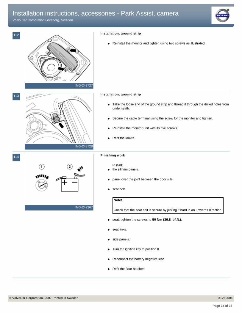
Finishing work
Install:● the sill trim panels.
● panel over the joint between the door sills.
● seat belt.
● seat, tighten the screws to 50 Nm (36.8 lbf.ft.).
● seat links.
● side panels.
● Turn the ignition key to position II.
● Reconnect the battery negative lead
● Refit the floor hatches.
Note!
Check that the seat belt is secure by jerking it hard in an upwards direction.
Installation instructions, accessories - Park Assist, camera Volvo Car Corporation Göteborg, Sweden
Installation instructions, accessories - Park Assist, camera Volvo Car Corporation Göteborg, Sweden
© VolvoCar Corporation, 2007 Printed in Sweden 31260504© VolvoCar Corporation, 2007 Printed in Sweden 31260504
Page 34 of 35
115
IMG-242268
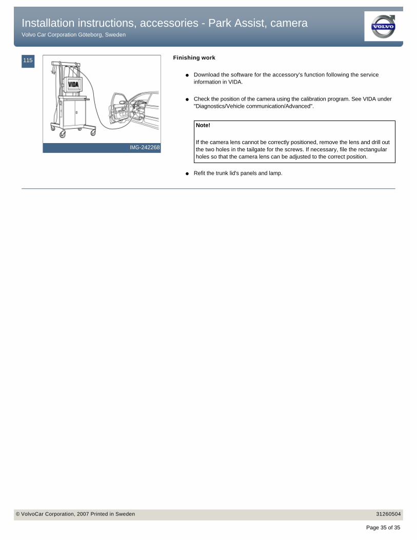
Finishing work
● Download the software for the accessory's function following the service information in VIDA.
● Check the position of the camera using the calibration program. See VIDA under "Diagnostics/Vehicle communication/Advanced".
● Refit the trunk lid's panels and lamp.
Note!
If the camera lens cannot be correctly positioned, remove the lens and drill out the two holes in the tailgate for the screws. If necessary, file the rectangular holes so that the camera lens can be adjusted to the correct position.
Installation instructions, accessories - Park Assist, camera Volvo Car Corporation Göteborg, Sweden
Installation instructions, accessories - Park Assist, camera Volvo Car Corporation Göteborg, Sweden
© VolvoCar Corporation, 2007 Printed in Sweden 31260504© VolvoCar Corporation, 2007 Printed in Sweden 31260504
Page 35 of 35