INSTALLATION INSTRUCTIONS · 7 rideriteo 10-32 x 3/4” machine screw 10-32 nylock nut 3/16” flat...
17
INSTALLATION INSTRUCTIONS riderite.com 2590 02-18
Transcript of INSTALLATION INSTRUCTIONS · 7 rideriteo 10-32 x 3/4” machine screw 10-32 nylock nut 3/16” flat...

INSTALLATION INSTRUCTIONS
riderite.com
2590
02-18

riderite.com1
IMPORTANTPLEASE DON’T HURT YOURSELF, THE KIT, OR YOUR VEHICLE. TAKE A MINUTE TO READ THIS IMPORTANT INFORMATION.
SAFE INSTALLATIONPlease take all safety precautions during installation. A hydraulic jack can fail, and if that happens, you can be seriously hurt, or worse, if you are relying on it to hold up the vehicle. If you use a hydraulic jack, secure jack stands in the appropriate locations and chock any tires still touching the ground.
Wear safety glasses or goggles. Your eyes may be lower than some parts and pieces, and you don’t want to lose an eye.
Remove the possibility of any electrical issues by disconnecting the negative battery cable.
VEHICLE GVWRNEVER exceed the maximum load recommended by the vehicle manufacturer (GVWR). The GVWR can be found in your vehicle’s owner’s manual or on the data plate on the driver’s side door. Consult your local dealership for additional GVWR specifications.
PRESSURE TO LOADBe sure to review the load limits noted in the Air Spring Kit Installation Instructions (sold separately).
APPROPRIATE AIR PRESSUREFor best ride, use only enough air pressure in the Air Springs to level the vehicle when viewed from the side (front to rear). This will vary, depending on the load, location of the load, condition of the existing suspension, and personal preference.
ONCE INSTALLED SUCCESSFULLY, FOLLOW THE PRESSURE REQUIREMENTS FOR THE AIR SPRINGS. FOR FIRESTONE, GENERALLY:
305 100510010

2590 Installation Instructions 2
PARTSCompare the parts below to your kit. Assure you have all pieces, and organize them for an easier installation.
MAIN KIT CONTENTS
PAR
T #
9490
x 1 WIRELESSCONTROLLER
PAR
T #
9489
x 1 ECU
PAR
T #
9499
x 1 AIR COMPRESSOR
PAR
T #
9491
x 1 WIRE HARNESSPA
RT
# 25
26x 1 IGNITION
FUSE TAP x 1 AIR FILTER
PAR
T #
9414
x 1 AIR LINE TUBE (18 FEET)
A21-760-2590 HARDWARE PACK
PAR
T #
3087
x 4 10-32 x 1" MACHINE SCREW
PAR
T #
3093
x 3 10-32 x 3/4"MACHINE SCREW
PAR
T #
3086
x 13 3/16" FLAT WASHER
PAR
T #
3088
x 7 10-32 NYLOCK NUT
PAR
T #
3055
x 11/8 NPT PUSH- TO-CONNECT STRAIGHT FITTING
PAR
T #
9361
x 1 SEALED RELAY
PAR
T #
3421
x 110-16 x 3/4" SELF-TAPPING SCREW
PAR
T #
9275
x 4 VELCRO TABS
PAR
T #
9036
x 15 RED NYLON TIE
PAR
T #
9488
PAR
T #
0899
x 4 LARGE NYLON TIE x 2 THERMAL SLEEVE
riderite.com3
CONTENTS AND OVERVIEWPAGE 4 PLANNING THE
INSTALL
PAGE 5 PREPARE THE AIR COMPRESSOR
PAGE 6DRILL HOLES FOR AIR COMPRESSOR AND ECU
PAGE 7INSTALL THE AIR COMPRESSOR AND ECU
PAGE 8 INSTALL THE WIRE HARNESS
PAGE 9 INSTALL THE AIR LINE TUBES
PAGE 10INSTALL THEAIR FILTER ANDCLEAN UP
PAGE
PAGE
PAGE 13 TEST THE SYSTEM
PAGE 14 FIX AN AIR LEAK
SUP
AS-1 AS-2
EXH
SUP
AS-1 AS-2
EXH
ECU
AIR SPRINGS(sold separately)
AIR LINE TUBE
AIR LINE TUBE
AIR LINETUBE
20 AMP FUSE
RED (+)
RED/WHITE
ECU CONNECTOR
RELAYCONNECTOR
(COMPRESSOR +)
BATTERY (+)
YELLOW
+12V IGN
OPTIONAL: Use supplied Fuse Tap. See important information on the Usingthe Fuse Tap sheet.
OPTIONAL: InstallAir Line Tube toEXH air fitting.See page 9 forimportant information.
LEFT AIR SPRING(when facing forward)
RIGHT AIR SPRING(when facing forward)
WIREHARNESS
SEALEDRELAY
* As a water/debris trap. See page 4.
Createloop in AirLine Tube.
BLACK (-)
BATTERY (-)
11 CONTROLLERUSING THE WIRELESS
12 FREQUENTLQUESTIONS
Y ASKED

2590 Installation Instructions 4
PLANNING THE INSTALLTHESE PLANNING STEPS WILL HELP YOU SAVE TIME AND WILL MAKE THE INSTALLATION EASIER.
DETERMINE THE MOUNTING LOCATION FOR THE AIR COMPRESSOR- Provides ample air flow and is protected from airborne debris and moisture.- Mount close enough to the ECU to allow Wire Harness connections to reach.- If using the optional Firestone Air Accessory Mounting Kit, consider the
guidelines above, and follow the kit’s instructions.
DETERMINE THE MOUNTING LOCATION FOR THE ECU- Mount close enough to the Air Compressor to allow Wire Harness
connections to reach.- Allow room for Air Line Tubes to connect to the air fittings on the ECU.- Allow room for the 14-pin ECU connector to connect to the ECU.- Allow room for the Air Line Tube to run without sharp curves or bends.- Using supplied fasteners shown in Step 3 is recommended. If no other mounting option is available,
see the sidebar on Step 2 for using the Large Nylon Ties.- Select a location that is solid and secure on the body or frame of the vehicle, away from any moving parts,
electrical or any other lines.
PLAN INSTALLATION ROUTES FOR WIRING AND AIR LINES- Make sure the Wire Harness and Air Line Tubes are not exposed to sharp metal edges that can damage them.- Use supplied Thermal Sleeves on Air Line Tubes when routing near heat sources.- Use supplied Nylon Ties to secure Air Line Tubes and Wire Harness to the vehicle.- Make a loop in the Air Line Tube where shown. This creates a water/debris trap that protects the Air Compressor.- Measure twice, cut once!
TAPE ALL ELECTRICAL CONNECTIONS- Use electrical tape to appropriately secure and protect all electrical connections.
USING PUSH-TO-CONNECT FITTINGS FOR AIR LINESYour kit includes Push-to-Connect fittings to connect the Air Line Tubes to hardware. Use the instructions below when using the Air Line Tubes.
1 Insert end of Air Line Tube into air fitting. 2 Push Air Line Tube
into air fitting asfar as possible. 3 Gently pull on
the Air Line Tube to check for a secure fit.
4 To remove, pushdown collar andgently pull Air LineTube away.
Removal Tip: Use a 1/4", 5/16", or 6mm open-ended wrench to push the collar down.

riderite.com5
PREPARE THE AIR COMPRESSOR1NOTE: Air Compressor can be mounted facing any direction.
1 Install 1/8 NPT Push-to-Connect Straight Fitting on the Check Valve.
1/8 NPT PUSH-TO-CONNECT STRAIGHT FITTINGTighten to engage two threadsof thread lock.
PRE-INSTALLEDCHECK VALVE

2590 Installation Instructions 6
If there is no othermounting option,use at least twoLarge Nylon Ties to secure ECU to the locationdetermined inPlanning theInstall section.
ECU
DRILL HOLES FOR AIR COMPRESSOR AND ECU 2
3/16”
IF YOU ARE USING THE OPTIONAL FIRESTONE AIR ACCESSORY MOUNTING KIT, SKIP THIS STEP AND REFER TO THE MOUNTING KIT’S INSTRUCTIONS.
CHECK SURROUNDING AREA AND BACK SIDE OF MOUNTING LOCATION TO AVOID DRILLING INTO EXISTING LINES OR WIRING.
1 Using the Air Compressor and ECU as templates, mark drill locations as shown with a punch or marking tool.
2Mark Air Compressor ground wire fasteninglocation within reach of the ground wire ring terminal.
3Drill 3/16" diameter holes. Remove any burrs and debris from drill holes.
ASSURE THAT YOU INSTALL THE AIR COMPRESSOR AND ECU CLOSE ENOUGH SO THE CONNECTORS ON THE WIRE HARNESS WILL REACH THEM BOTH.
OPTIONAL ECU MOUNTING
AIR COMPRESSORBLACKGROUND WIRE
Use as template to mark drill locations.
ECU
Use as template to mark drill locations.
Drill within reach of the ground wire ring terminal on body or frame of vehicle. AIR ACCESSORY MOUNTING KIT CANNOT BE USED AS A GROUNDING LOCATION FOR THE AIR COMPRESSOR.
riderite.com7
10-32 x 3/4” MACHINE SCREW
10-32 NYLOCK NUT
3/16” FLAT WASHER
3/16” FLAT WASHER
10-32 NYLOCK NUT
3/16” FLAT WASHER
SUP
AS-1 AS-2
EXH
SUP
AS-1 AS-2
EXH
ECU
(or optional FirestoneAir AccessoryMounting Kit).
BODY OR FRAMEOF VEHICLE
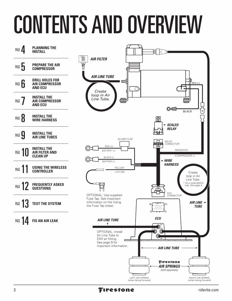
INSTALL THE AIR COMPRESSOR AND ECU3
DO NOT OVER TIGHTEN MOUNTING BOLTS AND NUTS ON THE AIR COMPRESSOR. TOO MUCH TORQUE CAN CRUSH THE BRASS INSERTS AND RUBBER ISOLATORS.
1 Mount the Air Compressor to the drill hole location using the supplied fasteners. DO NOT OVER TIGHTEN.
2 Mount the ECU to the drill hole location using the supplied fasteners. 3 Mount the black ground wire
ring terminal using the sup-plied fasteners. Assure that the ring terminal makes a solid contact with bare metal for a proper ground.
AIR COMPRESSOR
10-32 x 1” MACHINE SCREW
#10 FLAT WASHER
10-32 LOCK NUT#10 FLAT WASHER
10-32 LOCK NUT#10 FLAT WASHER
BLACKGROUND WIRE
Body of vehicle(or optional Firestone
Air AccessoryMounting Kit– Part #2588)
x 12x 2x 4 x 6
10-16 x 3/4” SELF-TAPPING SCREW NOTE: You may want to combine other grounds to this mounting location.
BODY OR FRAMEOF VEHICLEAir Accessory mounting Kit cannot be used as a grounding location for the Air compressor.

2590 Installation Instructions 8
INSTALL THE WIRE HARNESS 4
1 Determine a suitable location to mount the Sealed Relay, assuring it will be within reach of the relay connector on the Wire Harness.
2Securely fasten the Sealed Relay as shown.
3Route the Wire Harness in the most protected manner possible, and securely make all connections as shown.
RELAYCONNECTOR
Fully seat until male tab clickssecurely.
SEALEDRELAY
TAB CONNECTOR EXAMPLE
Why ground the Wire Harness to the battery? The ECU needs a good, clean ground for opti-mal accuracy. The Air Compressor can ground to the frame, but the ECU cannot.
SUP
AS-1 AS-2
EXH
SUP
AS-1 AS-2
EXH
ECU
20 AMP FUSE
RED 12V (+)
RED/WHITE
ECU CONNECTOR
RELAYCONNECTOR
(COMPRESSOR +)
BATTERY (+)
YELLOW
+12V IGN WIREHARNESS
BLACK (-)
BATTERY (-)
OPTIONAL: Use supplied Fuse Tap. See important information on the Usingthe Fuse Tap sheet.
SEALEDRELAYDrill 3/16”hole in suitable location on
vehicle (or use optional Firestone AirAccessory Mounting Kit).
10-32 x 3/4”MACHINE SCREW
SELF TAPPINGSCREWS
10-32NYLOCKNUT
3/16” FLAT WASHER
or
riderite.com9
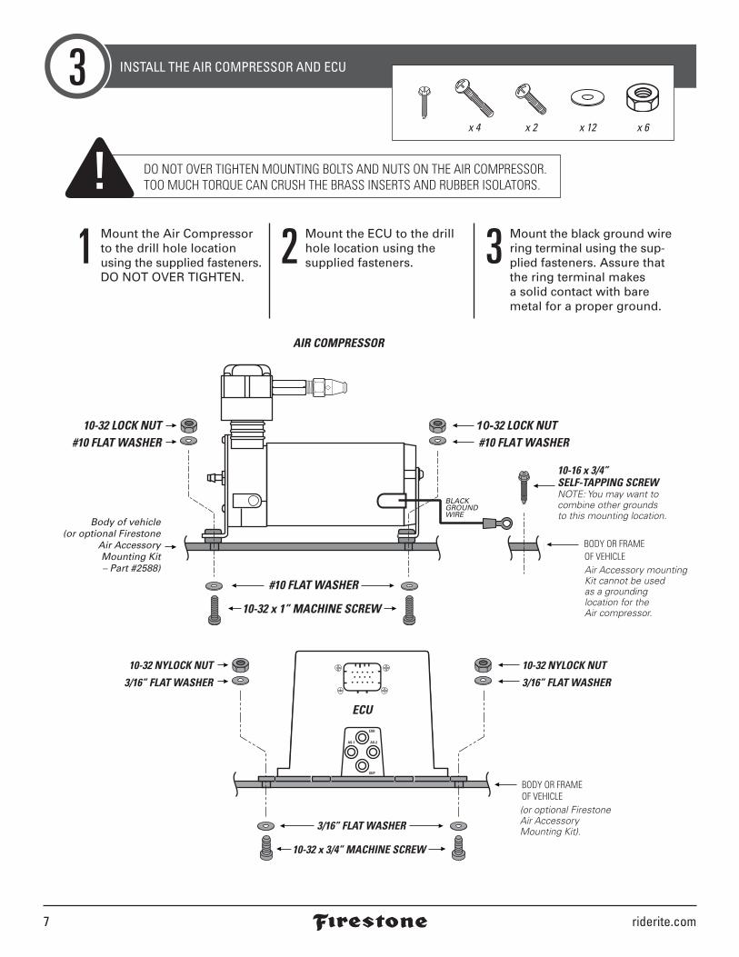
INSTALL AIR LINE TUBES5
DO Make sure the cut is as square as possible.Use a tube cutter or very sharp utility knife. DON’T
Fold or kink the Air Line Tube.Cut the Air Line Tube at an angle.Use pliers, scissors, snips,saws, or side cutters.
Square cut
90˚AIR LINE TUBE AIR LINE TUBE AIR LINE TUBE AIR LINE TUBE
PROPER AND IMPROPER CUTS IN THE AIR LINE TUBE
EXHAUST ALL AIR FROM THE SYSTEM PRIORTO RELEASING AIR TUBES FROM AIR FITTINGS. 5
PSI
1 Route the Air Line Tube from 1/8 NPT Push-to-Con-nect Straight Fitting on the top of the Air Compressor to the Supply (SUP) air fitting on the ECU, leaving room to secure it safely. Use the guidelines on page 4 for proper Push-to-Connect Straight Fitting install.
2Repeat Steps 1 to route Air Line Tube from the ECU to the Air Springs. Use the AS-1 and AS-2 air fittings on the ECU.
3If desired, install Air Line Tube to the Exhaust (EXH) air fitting to reduce exhaust noise and prevent dirt from clogging the port (recom-mended for off-road or dirty environments). Do not exceed 16" of Air Line Tube, and secure it so the end turns to the ground.
SUP
AS-1 AS-2
EXH
SUP
AS-1 AS-2
EXH
ECU
1/8 NPT PUSH-TO-CONNECTSTRAIGHT FITTING
AIR LINE TUBE
AIR LINE TUBE
OPTIONAL: Install Air Line Tube to the EXHair fitting - 16” max. Route to SUP
on ECU.
Route to AS-1on ECU.
Route to AS-2on ECU.
Route to EXH on ECU.
AIR LINETUBE
LEFT AIR SPRING(when facing forward)
RIGHT AIR SPRING(when facing forward)
* As a water/debris trap. See page 4.
Createloop in AirLine Tube.
AIR SPRINGS(sold separately)

2590 Installation Instructions 10
riderite.com11
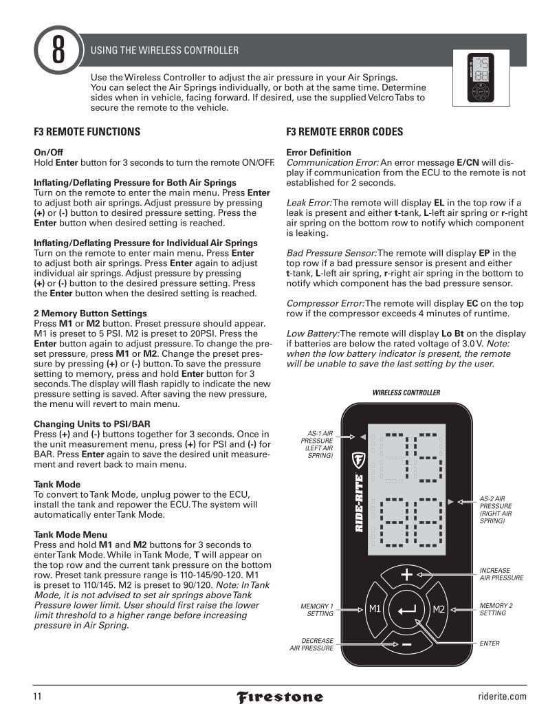
F3 REMOTE FUNCTIONS
On/OffHold Enter button for 3 seconds to turn the remote ON/OFF.
Inflating/Deflating Pressure for Both Air SpringsTurn on the remote to enter the main menu. Press Enter to adjust both air springs. Adjust pressure by pressing (+) or (-) button to desired pressure setting. Press the Enter button when desired setting is reached.
Inflating/Deflating Pressure for Individual Air SpringsTurn on the remote to enter main menu. Press Enter to adjust both air springs. Press Enter again to adjust individual air springs. Adjust pressure by pressing (+) or (-) button to the desired pressure setting. Press the Enter button when the desired setting is reached.
2 Memory Button SettingsPress M1 or M2 button. Preset pressure should appear. M1 is preset to 5 PSI. M2 is preset to 20PSI. Press the Enter button again to adjust pressure. To change the pre-set pressure, press M1 or M2. Change the preset pres-sure by pressing (+) or (-) button. To save the pressure setting to memory, press and hold Enter button for 3 seconds. The display will flash rapidly to indicate the new pressure setting is saved. After saving the new pressure, the menu will revert to main menu.
Changing Units to PSI/BARPress (+) and (-) buttons together for 3 seconds. Once in the unit measurement menu, press (+) for PSI and (-) for BAR. Press Enter again to save the desired unit measure-ment and revert back to main menu.
Tank ModeTo convert to Tank Mode, unplug power to the ECU, install the tank and repower the ECU. The system will automatically enter Tank Mode.
Tank Mode MenuPress and hold M1 and M2 buttons for 3 seconds to enter Tank Mode. While in Tank Mode, T will appear on the top row and the current tank pressure on the bottom row. Preset tank pressure range is 110-145/90-120. M1 is preset to 110/145. M2 is preset to 90/120. Note: In Tank Mode, it is not advised to set air springs above Tank Pressure lower limit. User should first raise the lower limit threshold to a higher range before increasing pressure in Air Spring.
F3 REMOTE ERROR CODES
Error DefinitionCommunication Error: An error message E/CN will dis-play if communication from the ECU to the remote is not established for 2 seconds.
Leak Error: The remote will display EL in the top row if a leak is present and either t-tank, L-left air spring or r-right air spring on the bottom row to notify which component is leaking.
Bad Pressure Sensor: The remote will display EP in the top row if a bad pressure sensor is present and either t-tank, L-left air spring, r-right air spring in the bottom tonotify which component has the bad pressure sensor.
Compressor Error: The remote will display EC on the top row if the compressor exceeds 4 minutes of runtime.
Low Battery: The remote will display Lo Bt on the display if batteries are below the rated voltage of 3.0 V. Note: when the low battery indicator is present, the remote will be unable to save the last setting by the user.
USING THE WIRELESS CONTROLLER8
WIRELESS CONTROLLER
AS-1 AIRPRESSURE
(LEFT AIRSPRING)
AS-2 AIRPRESSURE(RIGHT AIR SPRING)
INCREASEAIR PRESSURE
ENTERDECREASEAIR PRESSURE
MEMORY 1SETTING
MEMORY 2SETTING
Use the Wireless Controller to adjust the air pressure in your Air Springs. You can select the Air Springs individually, or both at the same time. Determine sides when in vehicle, facing forward. If desired, use the supplied Velcro Tabs to secure the remote to the vehicle.

2581 Installation Instructions 12
FREQUENTLY ASKED QUESTIONS 91) Why is my system not powering up?When the system does not power up, usually this is a strong indi-cation of improper power and grounding. Ensure that the powerline (red wire) is attached to a +12 volt power source (battery). Thegrounding line (black wire), should be rerouted back to the battery,not the frame of the car. Traditionally, techs have used the framethe car as a grounding source, but through experience, we haveseen that using the true ground (battery) offers the best connectionfor the device. Next, ensure that the yellow line is connected to theignition fuse located in your vehicles fuse box. Please make surethe fuse on the F3 wiring harness is installed and not blown. It isimportant to confirm with a meter (if possible) that the fuse is ononly when the ignition is engaged and off when the ignition is off.
2) Why are my buttons not responding correctly?When your remote controller appears to not operate as intended,some of the key items you need to check are: battery charge (+3v),proper connection to the ECU, EC/N Code (refer to #7), barriers thatare in between the ECU and the remote, proper powering (refer to #1).
3) Why is my compressor not shutting off?When your compressor stays on even after the ignition switch hasbeen placed to the off position, please ensure that the yellow line istied to a switched fuse in the fuse box. To ensure this, please use avolt meter to confirm that the line is on (+12v), if and only if the igni-tion switch is in the ON position, and OFF when in the off position.
4) My remote does not work inside my cabin. What should I do?With the improvements in technology, some cars are equippedwith other electronic equipment which may cause interference tothe F3 system. Others vehicles are equipped with noise cancelingmaterial and equipment which also play a role in the interferenceof the F3 connectivity. To check if either of these scenarios is true,confirm that your unit works properly if operated outside. If yourunit does operate as intended outside the vehicle, contact us forfurther solutions.
5) Why does my system not turn on when I turn the ignition on?When your F3 system does not turn on when the ignition switchis on the on position, this is a strong indicator that the unit is notpowered/grounded correctly. Please refer to question #1.
6) Why does my remote freeze when I am trying to change pressure?When your remote is freezing, this is an indication that the com-munication is out of range/ batteries have insufficient charge oryou may have a bad remote. If the batteries are low, replace thebatteries. If the communication range is over 30 meters, operatethe unit in close proximity. If the issue still persists, contact ourtech line to receive a replacement. In order to receive a placement,please have your receipt to show proof of purchase.
7) Why does my remote display “E/CN” when attempting tochange pressure?The “E/CN” code is an indicator that the remote is not communi-cating to the ECU. When this occurs, this is an indicator that theECU is not powered or the user is out of range. When the ECU isnot powered, please refer to question #1. If the user is out of range,ensure to get within the range of 30meters (98 feet).
8) What should I do when the remote goes to sleep before it meetsthe set pressure?Check battery voltage.
9) Is it normal for my compressor to be overworking when at-tempting to reach pressure?When the compressor sounds as if it is overworking to get topressure, relax. This is normal. The ECU was programmed to reachthe designated pressure as accurately as possible. To reduce theover usage of the compressor, use the system only when needed.Having two preset settings will reduce the over usage and increasethe system lifetime.
10) Why does my compressor run while exhausting continuously?When the compressor exhausts while running, ensure that theair line connections to the ECU are correct. The ECU has a sup-ply and exhaust line. If the unit is connected backwards, the ECUwill attempt to reach pressure, but won't since the connection isimproper. If the issue persists after confirming proper connection,check the valves next. The valve could have debris which is not al-lowing the valves to properly close. If shop air is available, engagethe valves with air to free the valves of debris. If the issue persists,please contact tech line for warranty claim.
11) Why does my compressor turn on and run by itself while driving?If the compressor turns on by itself while the vehicle is in motionand continuously runs, there is a relay that is energized by the bat-tery, and there is a potential wiring harness connection problem.It is possible that the ground terminal of the harness is improperlyconnected, or has become loose. Please check the connections ofthe harness to ensure that all terminals are properly connected. Ifall connections are secure and properly connected, please checkthe integrity of the relay connection to the compressor. It may bepossible that the relayis failing or has failed.
12) Why does my compressor still run when I turn the key off, evenwhen wired to an ignition source?Please confirm that the following are connected correctly:
A: The yellow ignition wire is properly connected to the correctfuse that connects to a switched source. There are some fuses that are always powered even when the vehicle’s ignition is turned off.
B: The red power wire is properly connected to the battery, preferably directly to the battery terminal to ensure that the relay is properly energized and reenergized during turn-on, turn-off cycles.
C: The black wire is properly attached to a ground path. A direct battery connection to the negative terminal is preferred.
13) Why does my compressor run, but dead heads at the ECU? The compressor usually stops operating if there is an improperconnection to the valve body inlets and outlets. If your compressorruns momentarily and then stops, please check the following:
A: The battery on the vehicle is in good working condition. It hasbeen observed that batteries with insufficient capacities have been unable to withstand compressor demands. Please check your compressor’s power rating, and confirm that the battery can meet the voltage and current demands.
B: Please confirm that the air lines are connected to their proper inlet or outlet valves. This will enable the compressor to properly operate as demanded by the user’s input.
14) Why does my controller show a completely different pressurethan what is actually in the bags?When the controller shows a completely different pressure, pleasecontact our tech line for a warranty claim. The ECU contains pres-sure sensor which can be faulty. Since the sensors are inside theECU, the unit needs to be replaced.
riderite.com13
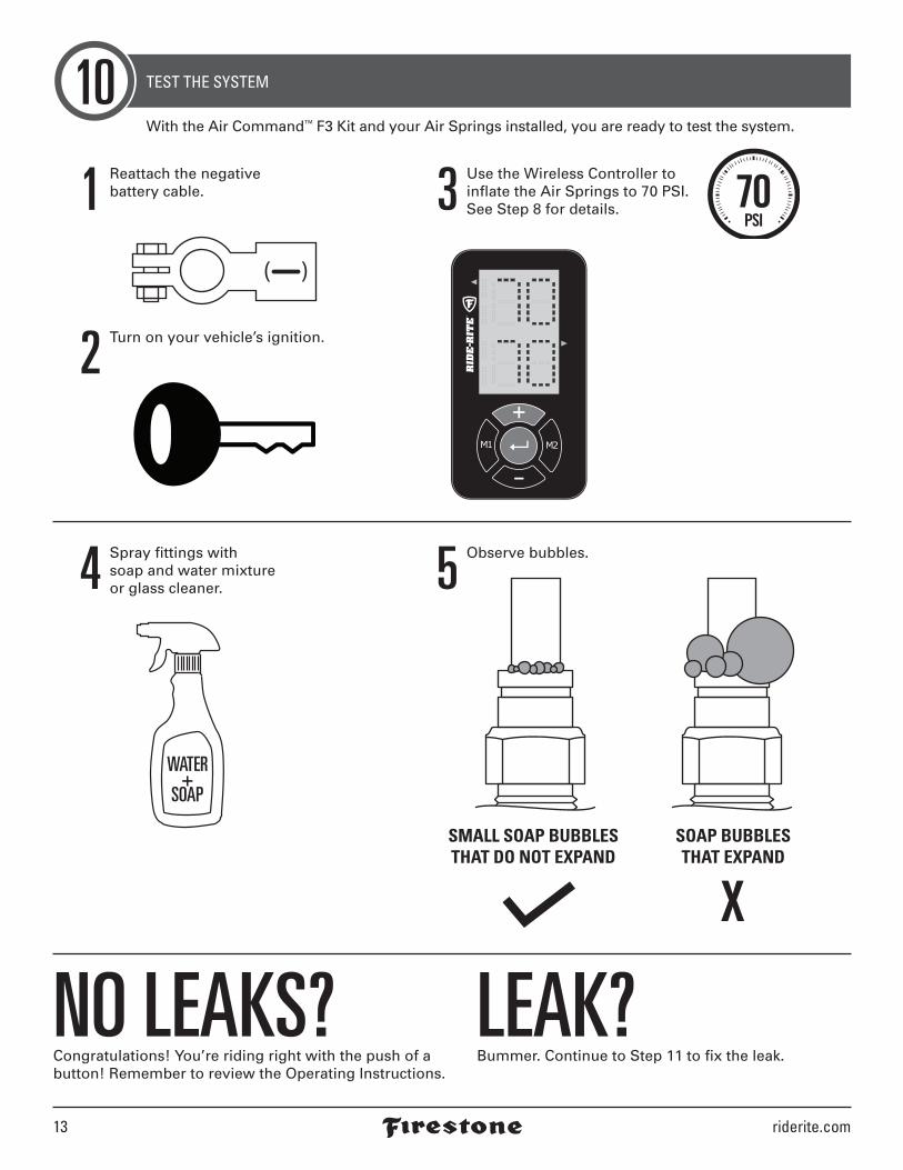
TEST THE SYSTEM10With the Air Command™ F3 Kit and your Air Springs installed, you are ready to test the system.
NO LEAKS?Congratulations! You’re riding right with the push of a button! Remember to review the Operating Instructions.
LEAK?Bummer. Continue to Step 11 to fix the leak.
1 Reattach the negative battery cable.
2 Turn on your vehicle’s ignition.
4 Spray fittings with soap and water mixture or glass cleaner. 5 Observe bubbles.
3 Use the Wireless Controller to inflate the Air Springs to 70 PSI. See Step 8 for details.
WATER+
SOAP
SMALL SOAP BUBBLESTHAT DO NOT EXPAND
SOAP BUBBLESTHAT EXPAND
2590 Installation Instructions 14
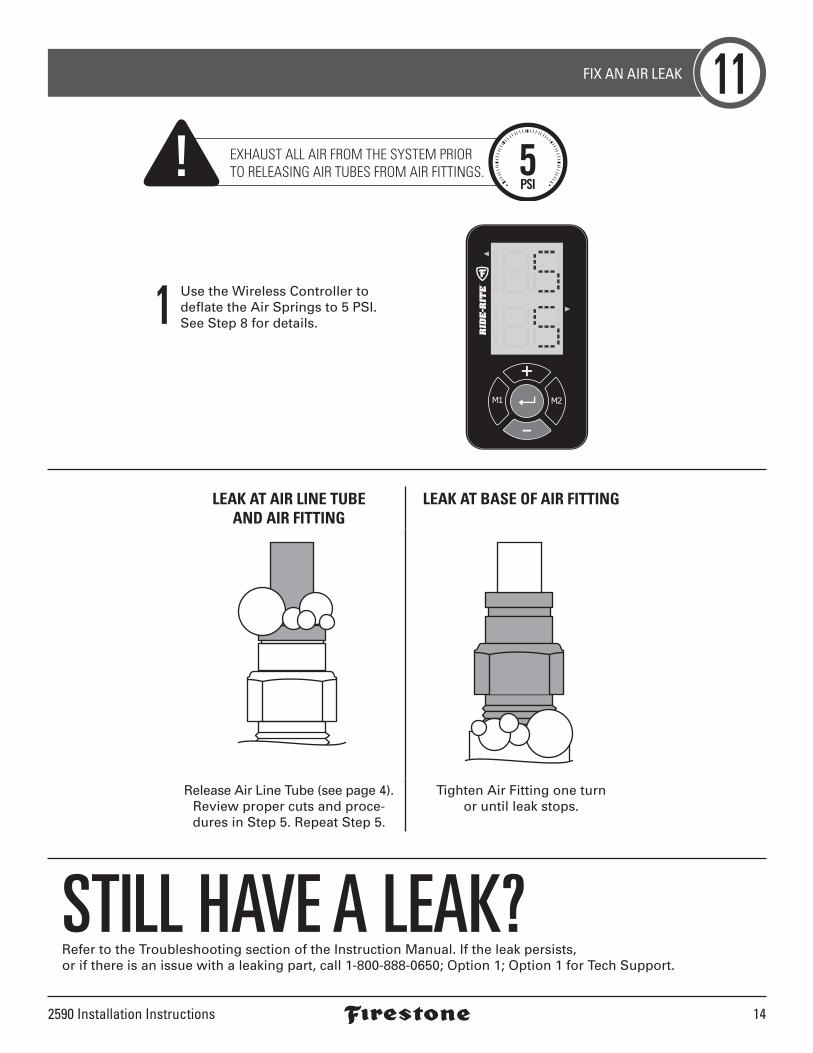
FIX AN AIR LEAK 11
STILL HAVE A LEAK?Refer to the Troubleshooting section of the Instruction Manual. If the leak persists, or if there is an issue with a leaking part, call 1-800-888-0650; Option 1; Option 1 for Tech Support.
LEAK AT AIR LINE TUBE AND AIR FITTING
LEAK AT BASE OF AIR FITTING
Release Air Line Tube (see page 4). Review proper cuts and proce-dures in Step 5. Repeat Step 5.
Tighten Air Fitting one turn or until leak stops.
1 Use the Wireless Controller to deflate the Air Springs to 5 PSI.See Step 8 for details.
EXHAUST ALL AIR FROM THE SYSTEM PRIORTO RELEASING AIR TUBES FROM AIR FITTINGS. 5
PSI

riderite.com
2590
02-18
CONNECT WITH US @rideriteair @rideriteair Firestone RideRite Firestone Ride-Rite
BEFORE YOU DRIVE, CONFIRM THE FOLLOWING: Secure all Air Line Tubes and wiring.
The system passes the leak test and holds air.
The Air Compressor ground ring terminal is contacting bare metal, and coated with silicone if possible.
The Wire Harness is grounded to the negative (-) battery terminal. The ECU needs a good, clean,
interference-free ground.
There is a loop in the Air Line Tubes as shown to prevent water or debris from getting into the Air
Compressor head and damaging it.
NEED INSTALLATION HELP? 1-800-888-0650Select Option 1 for Ride-Rite; Select Option 1 for Technical Support.
Or, email us at [email protected]. If emailing, please include photos to help us better diagnose and understand any problems you may be experiencing.

Fuse
fo
r ac
cess
ory
item
.
FUS
E P
OR
TO
N V
EH
ICLE
Fuse
rem
ove
d f
rom
veh
icle
fu
se b
ox.
+(H
OT
)S
IDE
LOA
DS
IDE
AC
CE
SS
OR
Y+1
2V IG
NP
OW
ER
WIR
E
+(H
OT
)S
IDE
LOA
DS
IDE
FUSE
TA
P
ride-
rite.
com
08-1
5USIN
G THE
IGNI
TION
FUSE
TAP
IT IS
VER
Y IM
PORT
ANT
TO ID
ENTI
FY T
HE H
OT
SIDE
OF
THE
FUSE
IN T
HE F
USE
BOX.
IT C
OU
LD
BE
ON
EIT
HER
SID
E, R
EGA
RDLE
SS O
F TH
E FU
SE O
RIEN
TATI
ON
. FUS
E TA
P M
UST
BE
INSE
RTED
AS
SHOW
N. D
O N
OT
REVE
RSE.
Use
a m
ultim
eter
to d
eter
min
e w
hich
sid
e of
the
fuse
por
t on
the
vehi
cle
is h
ot. S
et
the
mul
timet
er to
test
vol
tage
, the
n us
e th
e re
d pr
obe
to te
st e
ach
port.
The
sid
e th
at
gets
a re
adin
g be
twee
n 11
.8 V
DC
and
15 V
DC
is th
e ho
t sid
e. A
ssur
e yo
u ha
ve a
pr
oper
gro
und
with
the
blac
k pr
obe.
Do
not
use
a fu
se te
ster
for t
his,
as
it co
uld
light
up
with
out t
he p
rope
r ran
ge n
oted
abo
ve.
1Inse
rt t
he
fuse
fo
r th
e Fi
rest
on
e ac
cess
ory
in
to t
he
top
Fu
se T
ap
po
rt, a
s sh
ow
n.
2Use
yo
ur
veh
icle
’s O
wn
er’s
Man
ual
to
d
eter
min
e a
safe
an
d s
uit
able
ign
itio
n
fuse
an
d r
emo
ve t
he
fuse
, no
tin
g it
s
loca
tio
n. T
his
loca
tio
n s
ho
uld
reg
iste
r
bet
wee
n 1
1.8
VD
C a
nd
15
VD
C w
hen
te
stin
g w
ith a
mul
timet
er, a
s no
ted
belo
w.
3Inse
rt t
he
rem
ove
d f
use
fr
om
yo
ur
veh
icle
into
th
e lo
wer
Fu
se T
ap p
ort
, as
sh
ow
n.
4Plu
g t
he
Fuse
Tap
into
th
e fu
se p
ort
on
th
e ve
hic
le,
mat
chin
g t
he
ho
t an
d lo
ad
sid
es, a
s sh
ow
n. D
O N
OT
R
EV
ER
SE
.