INSTALLATION INSTRUCTION FORFOR CONSTANT SPRING HANGER
16
INSTALLATION INSTRUCTION INSTALLATION INSTRUCTION INSTALLATION INSTRUCTION INSTALLATION INSTRUCTION FOR FOR FOR FOR CONSTANT SPRING HANGER CONSTANT SPRING HANGER CONSTANT SPRING HANGER CONSTANT SPRING HANGER
Transcript of INSTALLATION INSTRUCTION FORFOR CONSTANT SPRING HANGER

INSTALLATION INSTRUCTIONINSTALLATION INSTRUCTIONINSTALLATION INSTRUCTIONINSTALLATION INSTRUCTION
FORFORFORFOR
CONSTANT SPRING HANGERCONSTANT SPRING HANGERCONSTANT SPRING HANGERCONSTANT SPRING HANGER
QUALITY ASSURANCE PROGRAMME
MAIN SECTION : HANDLING, STORAGE AND SHIPPING Document No.: FS-13C-01
Revision No.: 1
Revision Date: 98-12-01
SUBJECT : INSTALLATION INSTRUCTION-CONSTANT SUPPORT Page 1 of 15
1.0 PURPOSE ------------------------------------------------------------
1.1 This procedure have been prepared to provide installation instructions for the piping erector.
2.0 SCOPE ------------------------------------------------
2.1 This instruction outlines the recommended field practices for field personnel during hanger erection, adjustment, and inspection.
3.0 DEFINITION ------------------------------------------------------------------------
3.1 Cold Setting : The position at which a spring hanger indicator is set denoting the proper installation setting of the unit with the piping in the cold position.
3.2 Hot Setting : The position at which the indicator on a spring hanger should be with the piping in the hot or operating position.
3.3 Piping Erector : The contractor who is directly responsible for the installation of pipe hanger assemblies and the erection of piping.
3.4 Component : Any of a range of devices which are used to make up a pipe hanger assembly.
3.5 Erection : That activities associated with installing pipe hanger assembly for the supporting of the piping.
4.0 RESPONSIBILITY ------------------------------------------------------------------------------------------------
4.1 Piping erector shall control installation as defined in the job specifications for each classification of piping.
4.2 Piping erector or end user shall use the installed hanger or hanger components only for their intended purpose. They shall not be used for rigging or erection purpose.
FORM UNS-A-302-3 REV.0
A4(210××××297㎜㎜㎜㎜)
QUALITY ASSURANCE PROGRAMME
MAIN SECTION : HANDLING, STORAGE AND SHIPPING Document No.:
FS-13C-01
Revision No.: 1
Revision Date: 98-12-01
SUBJECT : INSTALLATION INSTRUCTION-CONSTANT SUPPORT Page 2 of 15
4.3 This document is the property of Unison. It shall not be copied or duplicated in any cases and shall not be submitted to outside parties for protection. And it shall not be used for the installation of other contractor's products.
5.0 CONSIGNEE STORAGE ------------------------------------------------------------------------------------------------------------------------
5.1 Storage should be in a dry area, enclosed for security purposes, and protected from the direct effects of weather and dirt.
5.2 It is recommended that containers be opened and contents be verified before they are placed in the storage area.
5.3 It is recommended that a system be established to facilitate retrieval of material from storage.
6.0 GENERAL ------------------------------------------------------------
6.1 Unison pipe hangers are designed and engineered to support piping systems and piping system components. Standard pipe hangers, either singly or in combination with other standard or special supports, are arranged according to the hanger drawing at each support point. During installation, each assembly must be installed in the location shown on the hanger drawing or piping erector's installation drawing with in the tolerances listed. Any deviation outside the allowed tolerances shall be justified by the piping erector.
6.2 Use of pipe hangers as erection devices in applications other than those for which they were designed can cause hanger failure resulting in property damage and personnel injury. If in doubt concerning a particular application contact your Unison representative. 6.3 Usually each hanger assembly is made of three parts, a structural attachment, a pipe attachment, and an intermediate assembly. Structural attachments shall be installed by welding, clamping, or bolting to structural beams, columns, or embedded plates.
FORM UNS-A-302-3 REV.0
A4(210××××297㎜㎜㎜㎜)

QUALITY ASSURANCE PROGRAMME
MAIN SECTION : HANDLING, STORAGE AND SHIPPING Document No.:
FS-13C-01
Revision No.: 1
Revision Date: 98-12-01
SUBJECT : INSTALLATION INSTRUCTION-CONSTANT SUPPORT Page 3 of 15
6.4 Welding of structural attachments shall be done in accordance with the rules of AWS D1.1. NDE requirements shall be as shown on the hanger drawing. When the preparation of the hanger drawing is out of Unison scope, the piping erector's installation drawing shall be used.
6.5 Pipe attachments shall be either standards pipe clamps, special clamps, or integral attachments. Integral attachment shall be made according to the rules governing the component and are not covered in these instructions. Special installation instructions for double bolt pipe clamps are prepared separately.
6.6 Intermediate assemblies shall be either rigid or resilient and shall be arranged as shown on the drawing.
6.7 After final adjustments of the hanger are made, all threaded fasteners shall have engagements which meet the following requirements. No adjustments shall be made that will result in less than full thread engagement.
6.7.1 For nuts, clevises, forged turnbuckles, threaded eye nuts, and other similar devices, the male thread shall fully engage the female thread.
6.7.2 For load couplings and other devices have sight holes, the male thread must be visible in the sight hole. For three hole fabricated turnbuckles, the center hole should be clear. For single hole load couplings, both male threaded parts must be visible in the sight hole and they must be tightened against each other to prevent loosening.
6.7.3 Failure to have proper thread engagement before application of load can result in release of load and possible property damage or personal injury.
6.8 Jam nuts are supplied with many products to prevent threaded members from turning during erection, adjustment, and service. They should be installed have tight and then wrench tightened at least 1/8 turn. For course threads, where this requirement would be excessive, wrench tight is sufficient.
FORM UNS-A-302-3 REV.0
A4(210××××297㎜㎜㎜㎜)

QUALITY ASSURANCE PROGRAMME
MAIN SECTION : HANDLING, STORAGE AND SHIPPING Document No.:
FS-13C-01
Revision No.: 1
Revision Date: 98-12-01
SUBJECT : INSTALLATION INSTRUCTION-CONSTANT SUPPORT Page 4 of 15
6.9 The security of the jam nut should be verified after hydrostatic testing. When the hydrostatic testing is not required, the security of the jam nut should be verified after first loading.
6.10 Threaded rods may have to be chased with a die for simplified assembly. In this instance, over chasing shall not be done. It is not recommended to break threads or tack weld as a means of locking unless so specified on hanger drawings.
6.11 Adjustability features shall be provided to facilitate pipe load distribution.
7.0 INSTALLATION OF CONSTANT SUPPORT --------------------------------------------------------------------------------------------------------------------------------------------------------------------------------------------
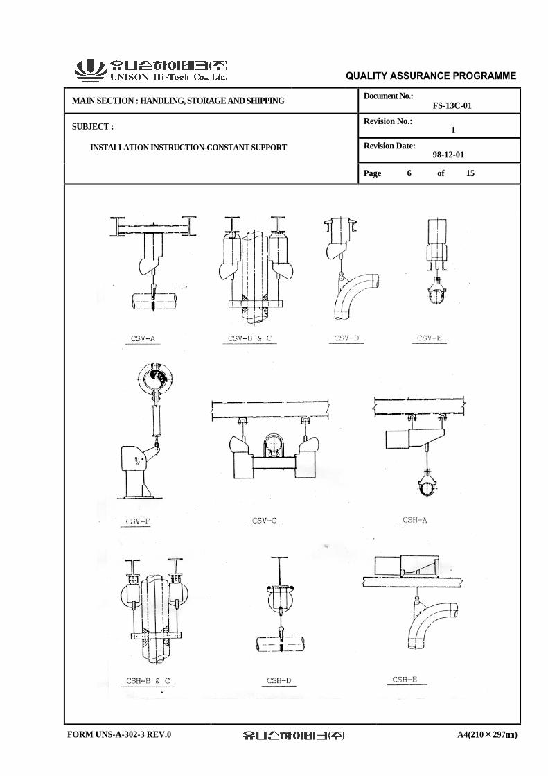
7.1 Unison's Constant Supports are classified in several models and types, which are identified by means of the symbols shown below. Detail dimensions and features may be found on the Unison's Pipe Hangers Catalog or dimensioned outline drawings approved by Customer.
Symbols : CSH-B-35, for example.
CS H B 35
------- ------- ------- -------
①①①① ②②②② ③③③③ ④④④④
FORM UNS-A-302-3 REV.0
A4(210××××297㎜㎜㎜㎜)

QUALITY ASSURANCE PROGRAMME
MAIN SECTION : HANDLING, STORAGE AND SHIPPING Document No.:
FS-13C-01
Revision No.: 1
Revision Date: 98-12-01
SUBJECT : INSTALLATION INSTRUCTION-CONSTANT SUPPORT Page 5 of 15
NO. SYMBOL DESCRIPTION
①①①① CS STANDS FOR CONSTANT SUPPORT
②②②②
H or V
INDICATES HANGER MODEL AS FOLLOWS; H : HORIZONTAL MODEL V : VERTICAL MODEL
③③③③ A, B, C, D E, F or G
INDICATES HANGER TYPE AS SHOWN ON NEXT PAGE. HORIZONTAL MODEL HAS TYPE A,B,C,D AND E ONLY.
④④④④
A NUMERAL FROM 1 TO 110
INDICATES SIZES. SEE LOAD TRAVEL TABLE, PAGE 40 THRU 43 IN OUR CATALOG. BY THE WAY ; 1) SIZE 1 THRU 9 ARE AVAILABLE IN MODEL CSH ONLY. 2) SIZE 84 THRU 110 ARE AVAILABLE IN MODEL
CSV TYPE A,B AND C AND MODEL CSH TYPE A,B,C AND E.
7.2 The Constant Support provides a constant supporting force throughout its entire travel range. That is, the supporting force does not vary with pipe deflection but remains constant.
7.3 Each Constant Support has a position scale marked H-M-L, indicating High, Mid and Low positions, respectively.
Thus, if the travel indicator of the hanger were at the "H" position, the hanger would be at its maximum up or high position. conversely, if the indicator were at "L", the hanger would be at its lowest position.
7.4 There are two markers placed on the travel scale at the factory, a blue marker corresponding to the cold position of the pipe, and red marker
corresponding to the hot position of the pipe.
FORM UNS-A-302-3 REV.0
A4(210××××297㎜㎜㎜㎜)
QUALITY ASSURANCE PROGRAMME
MAIN SECTION : HANDLING, STORAGE AND SHIPPING Document No.:
FS-13C-01
Revision No.: 1
Revision Date: 98-12-01
SUBJECT : INSTALLATION INSTRUCTION-CONSTANT SUPPORT Page 6 of 15
FORM UNS-A-302-3 REV.0
A4(210××××297㎜㎜㎜㎜)

QUALITY ASSURANCE PROGRAMME
MAIN SECTION : HANDLING, STORAGE AND SHIPPING Document No.:
FS-13C-01
Revision No.: 1
Revision Date: 98-12-01
SUBJECT : INSTALLATION INSTRUCTION-CONSTANT SUPPORT Page 7 of 15
7.5 Installation Sequence : 7.5.1 First of all, in order to avoid a wrong installation, an identification check must be performed by confirming the Hanger Identification No., Hanger Type and Size carved on the Name Plate (Aluminum or Stainless Steel Plate) attached on to the Hanger Side Plate.
7.5.2 Weld the structural attachments, such as Beam Attachment, Lug Plate or Washer Plate to the building structure as indicated on the hanger drawings approved by customer. Sometimes the structural attachments may be reinforced concrete and, in this case, the structural attachments can be welded to an embedded plate. Where Beam Clamps or Concrete Lug Plates are used, fasten these structural attachments with bolts and nuts.
7.5.3 Attachment of Constant Support
1) Type A, B and C Connect the Constant Support to the structural attachment using wire or chain block in order to connect it easily.
2) Type D, E and F Locate the Constant Support at the correct position and weld or bolt it in accordance with the instructions specified on the hanger drawings.
FORM UNS-A-302-3 REV.0
A4(210××××297㎜㎜㎜㎜)

QUALITY ASSURANCE PROGRAMME
MAIN SECTION : HANDLING, STORAGE AND SHIPPING Document No.:
FS-13C-01
Revision No.: 1
Revision Date: 98-12-01
SUBJECT : INSTALLATION INSTRUCTION-CONSTANT SUPPORT Page 8 of 15
3) For type G Constant Support, after attachment of structural attachments and pipe attachments, assemble the hanger rods to the Constant Support and connect it to the structural attachments and pipe attachments.
4) To help alleviate the problem of lifting large size spring hangers into position for installation, this product is available with lifting lugs (if requested) on sizes weighing forty (40) killograms and more.
7.5.4 Connect the pipe attachments to the pipe in accordance with the approved hanger drawings.
7.5.5 Assemble the hanger rods and other components to the pipe attachment and load coupling of Constant Support in accordance with the hanger drawing. Use of high temperature grease between load coupling and load yoke is recommended.
7.5.6 The hanger rod must be inclined no more than five (5) degree from the vertical, unless otherwise specified on the hanger drawing.
7.5.7 Be careful about the offset divergence specified on the approved drawings, where the horizontal movement is comparatively large.
8.0 ADJUSTMENT OF THE INSTALLATION LENGTH --------------------------------------------------------------------------------------------------------------------------------------------------------------------------------------------------------------------
8.1 The adjustment of installation length of the hanger assemblies is done by turning the load coupling when the installation work is done. 8.2 Warning The turnbuckle is normally not needed for Constant Support. If longer hanger rod is required, the rod coupling may be used for extension of hanger rod.
FORM UNS-A-302-3 REV.0
A4(210××××297㎜㎜㎜㎜)
QUALITY ASSURANCE PROGRAMME
MAIN SECTION : HANDLING, STORAGE AND SHIPPING Document No.:
FS-13C-01
Revision No.: 1
Revision Date: 98-12-01
SUBJECT : INSTALLATION INSTRUCTION-CONSTANT SUPPORT Page 9 of 15
9.0 TRAVEL STOPS --------------------------------------------------------------------------------
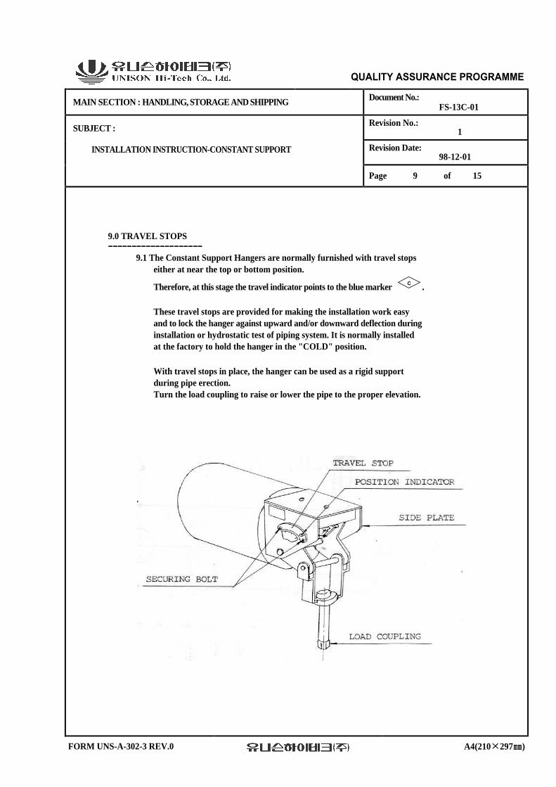
9.1 The Constant Support Hangers are normally furnished with travel stops either at near the top or bottom position.
Therefore, at this stage the travel indicator points to the blue marker C .
These travel stops are provided for making the installation work easy and to lock the hanger against upward and/or downward deflection during installation or hydrostatic test of piping system. It is normally installed at the factory to hold the hanger in the "COLD" position.
With travel stops in place, the hanger can be used as a rigid support during pipe erection. Turn the load coupling to raise or lower the pipe to the proper elevation.
FORM UNS-A-302-3 REV.0
A4(210××××297㎜㎜㎜㎜)

QUALITY ASSURANCE PROGRAMME
MAIN SECTION : HANDLING, STORAGE AND SHIPPING Document No.:
FS-13C-01
Revision No.: 1
Revision Date: 98-12-01
SUBJECT : INSTALLATION INSTRUCTION-CONSTANT SUPPORT Page 10 of 15
9.2 After all piping is installed, and after hydrostatic testing at ambient temperatures, all travel stops must be removed before system operation. Two different types of travel stop can be provided as per customer's requirement. 9.2.1 Standard Type The travel stops are attached both hanger side plates with two or more bolts. The travel stops are removed as follows : 1. Rotate the load coupling until the socketed position indicator is no longer a load bearing member. If this condition cannot be obtained, please refer to para 9.3, 9.8 and 9.9. 2. Remove bolts which secure stop plate to the hanger side plate. 9.2.2 Universal Type The travel stops consists of two plates with matched serrations attached to the hanger side plate with two or more bolts and which a socketed piece which engages the position indicator. A series of serrations can be engaged to lock the hanger at any position along the total travel range. The travel stop, which is furnished only when specified, is painted red. The travel stop is removed as follows : 1. Rotate the load coupling until the socketed piece which engages the position indicator is no longer a load bearing member. If this condition cannot be obtained, please refer to para 9.3, 9.8 and 9.9. 2. Remove bolts which secure serrated plates to the hanger side plate. 3. Swing stops to a position where they do not impair hanger operation or obstruct view of the travel scale and position indicator. 4. Securely fasten stops to hanger side plate and retain bolts for possible future use.
FORM UNS-A-302-3 REV.0
A4(210××××297㎜㎜㎜㎜)

QUALITY ASSURANCE PROGRAMME
MAIN SECTION : HANDLING, STORAGE AND SHIPPING Document No.:
FS-13C-01
Revision No.: 1
Revision Date: 98-12-01
SUBJECT : INSTALLATION INSTRUCTION-CONSTANT SUPPORT Page 11 of 15
5. Travel stop installation and removal instructions. The entire Travel Stop, painted red, consists of piece "A", Piece "B" (fastened to piece "A") and hex head bolts "C" and "D".
Don not remove Travel Stop before hanger is installed, fully Loaded and Hydrostatic Test completed.
To disengage Travel Stop, remove hex head bolts "C" and "D" which fasten piece "A" to the frame. It is not necessary to loosen nut "E".
When Travel Stop is not in use, it may be stored by hanging piece "A" and "B" from Bolt "C". Bolt "D" may be stored in threaded hole provided in frame.
The re-engage Travel Stop, loosen Nut "E", position moveable Piece "B" onto Travel Indicator, and replace and tighten Bolts "C", "D", and Nut "E".
FORM UNS-A-302-3 REV.0
A4(210××××297㎜㎜㎜㎜)

QUALITY ASSURANCE PROGRAMME
MAIN SECTION : HANDLING, STORAGE AND SHIPPING Document No.:
FS-13C-01
Revision No.: 1
Revision Date: 98-12-01
SUBJECT : INSTALLATION INSTRUCTION-CONSTANT SUPPORT Page 12 of 15
6. Warning ; 1) Never insert anything other than travel stops in the travel indicator slot as severe personal injury can result. 2) If travel stops must be removed prior to any testing or cleaning of the system done at ambient temperatures, and if this causes greater loads than the design loads, temporary supports must be provided. 9.3 As the hangers were provided with travel stops factory set at the cold position, no further adjustments should be necessary. If, however, any of the hangers are not at the proper setting, turn the load coupling until the travel indicator is at the blue, "COLD", marker. This procedure does not change the supporting force of the hanger, but assures the hanger capability of following the actual piping expansion and contraction. 9.4 After all piping is installed, and after hydrostatic testing at ambient temperatures all travel stops must be removed before system operation. This is accomplished by a slight turning of the load coupling until the stops are loose and can be easily removed. 9.5 If travel stops must be removed prior to any testing or cleaning of the system that will be done above ambient temperatures, and if this cause greater loads than the design loads, temporary supports must be provided by the piping erector. 9.6 If is suggested that the stops be wired to the hanger for possible future use. 9.7 Just prior to the operation of the piping system, a final check of the cold load settings of the Constant Support Hangers should be done, and after that, the travel stops can be removed. 9.8 The hangers are provided with travel stops factory set to the cold load, so no adjustment in load should be necessary. If, however, an occasional hanger is not at the "COLD" marking on the hanger casing, turn the load coupling of the Constant Support Hanger until the load indicator is at the blue "COLD" marker. However, before any adjustment is made, the position of the travel indicator on all spring units on the system should be recorded.
FORM UNS-A-302-3 REV.0
A4(210××××297㎜㎜㎜㎜)

QUALITY ASSURANCE PROGRAMME
MAIN SECTION : HANDLING, STORAGE AND SHIPPING Document No.:
FS-13C-01
Revision No.: 1
Revision Date: 98-12-01
SUBJECT : INSTALLATION INSTRUCTION-CONSTANT SUPPORT Page 13 of 15
9.9 After performing the preceding steps, any units which indicate an abnormal load condition to the extent that the spring indicator comes up against either the top ar bottom, the Unison support designer should be notified immediately. No substitution or modification should be made without specific instructions.
9.10 Tighten all jam nuts as specified in article 6.0.
9.11 Warning 9.11.1 Attempting to remove travel stops without all load removed from the stops can result in property damage and personnel injury. 9.11.2 Never fail to remove the travel stops before operation.
10.0 PRE-OPERATIONAL INSPECTIONS ------------------------------------------------------------------------------------------------------------------------------------------------------------
10.1 Confirm that travel stops have been removed.
10.2 Confirm that the travel indicator is located near the cold position marked C .
11.0 IN-SERVICE INSPECTIONS ----------------------------------------------------------------------------------------------------------------------------
11.1 Each hanger should be periodically inspected visually to verify the correct setting of the travel indicator during operation. Inspection frequency may be at each scheduled shut-down, unless otherwise specified. Annual Inspection, at least, is recommended. 11.2 If the travel indicator is not located at or near the designed position
marked H or marked C dur ing operation or plant shut-down, it should be adjusted to the appropriate operation or cold position by turning load coupling. When an un-predicted movement greater than the total travel range of the hanger is detected, the hanger should be replaced to fit the movement. 11.3 All dust, soot and foreign objects which may impair hanger operation shall be removed. 11.4 When rust or corrosion has been detected on the hanger components, repair of coating is preferred even if it is partial. Especially for outdoors assemblies, this kind of maintenance work is very effective in ensuring a long period of durability of hangers.
FORM UNS-A-302-3 REV.0
A4(210××××297㎜㎜㎜㎜)

QUALITY ASSURANCE PROGRAMME
MAIN SECTION : HANDLING, STORAGE AND SHIPPING Document No.:
FS-13C-01
Revision No.: 1
Revision Date: 98-12-01
SUBJECT : INSTALLATION INSTRUCTION-CONSTANT SUPPORT Page 14 of 15
11.5 Observe and record the position of the travel indicator once a year in hot and cold states. When an unexpected movement has been detected, the cause must be investigated.
11.6 Loose or fallen nuts should be tightened. 11.7 Damaged parts are to be repaired or replaced. 11.8 For inspection, a form suggested is attached. 11.9 In hot state, travel indicator should be of the indicator slit. Unless it is touching the edge, wherever the indicator is located, the Constant Support Hanger may be regarded as correctly supporting the specified load.
12.0 INSTRUCTIONS FOR LOAD ADJUSTMENTS ----------------------------------------------------------------------------------------------------------------------------------------------------------------------------------------------------
Load adjustment in the field is not required under normal conditions because delivered hanger has been already adjusted to the specified load in the factory. However, when an adjustment in the field is required because of any mis-load-calculation or revision, the load adjustment can be made by turning the load Adjusting Bolt. Field adjustment up to plus or minus 10% of the calibration load can be made. The percentage increase or decrease from the factory adjusted load should be carefully calibrated by an arrow die-stamped on the load scale plate.
FORM UNS-A-302-3 REV.0
A4(210××××297㎜㎜㎜㎜)

QUALITY ASSURANCE PROGRAMME
MAIN SECTION : HANDLING, STORAGE AND SHIPPING Document No.:
FS-13C-01
Revision No.: 1
Revision Date: 98-12-01
SUBJECT : INSTALLATION INSTRUCTION-CONSTANT SUPPORT Page 15 of 15
13.0 ATTACHMENT ----------------------------------------------------------------------------
13.1 HANGER RECORD SHEET
FORM UNS-A-302-3 REV.0
A4(210××××297㎜㎜㎜㎜)