Installation instruction do88 performance t Turbo intake … · Installation instruction do88...
10
Installation instruction do88 performance Turbo intake hoses Porsche 911 TT (997.2) 2010-2012 Part number: do88-kit169 This instruction shows how to replace the OEM turbo intake pipes for do88 performance hoses. In this instruction you will cut off both OEM turbo intake pipes to be able to remove them. If you don’t want to do that the engine must be lowered which is not described in this instruction. At this type of installation we always recommend that you have mechanical experience and knowledge about safety during work on vehicles. Parts included: 1. Left turbo inlet pipe 1pc 2. Right turbo inlet pipe 1pc 3. CNC machined VGT adapters 2pcs 4. VGT adapter o-rings 5. Hose clamps 7pcs 6. Screws M6 4pcs 7. Zip tie 1pc 1. 2. 3. 4. 5. Note! Be aware that it is a very tight fit installing these larger turbo intake hoses on the 997.2 Turbo. The hoses may not have free clearance all the way, they might push or rub in some areas. 6. 7.
-
Upload
nguyenthien -
Category
Documents
-
view
225 -
download
0
Transcript of Installation instruction do88 performance t Turbo intake … · Installation instruction do88...

Installation instruction do88 performance Turbo intake hoses Porsche 911 TT (997.2) 2010-2012
Part n
um
ber: d
o88
-kit169
This instruction shows how to replace the OEM turbo intake pipes for do88 performance hoses.
In this instruction you will cut off both OEM turbo intake pipes to be able to remove them.If you don’t want to do that the engine must be lowered which is not described in this instruction.
At this type of installation we always recommend that you have mechanical experience and knowledge about safety during work on vehicles.
Parts included:1. Left turbo inlet pipe 1pc2. Right turbo inlet pipe 1pc3. CNC machined VGT adapters 2pcs4. VGT adapter o-rings5. Hose clamps 7pcs6. Screws M6 4pcs7. Zip tie 1pc
1.2.
3.
4.
5.
Note! Be aware that it is a very tight fit installing these larger turbo intake hoses on the 997.2 Turbo.The hoses may not have free clearance all the way, they might push or rub in some areas.
6.
7.

2. Lift and secure the car so both rear wheels can be safely removed.
3. From each rear part of the rear inner fenders, Remove 5pcs Torx T25 screws.
4. Remove the 4pcs Torx T30 along the top of the bumper.
1. Open both the engine lid and luggage compartment lid.Disconnect the negative battery terminal. Note! Do not close the luggage compartment lid after you have removed the battery terminal.

5. Loosen 2x Torx T25 and gently pull the rear light straight back. Disconnect the cable connector. Do this on both sides.
6. Remove 1pc of plastic Torx T30 screw. After the screw has been removed gently peel away the plastic rivet. Do this on both sides.
7. Remove 6pcs Torx T30 screws along the bottom of the bumper.
8. Remove 1pcs Torx T30 screw in the top end of the bumper inside each wheel housing.

9. Now remove the rear bumper. With the help of a friend, gently pull each corner of the bumper out from the wheel house edge a bit. Then pull the bumper straight back. Disconnect the cable going to the bumper.
10. Remove the Y-pipe. 4pcs hose clamps1pc cable connector1pc vacuum line click connection.
11. Remove the air filter box. Loosen the two hose clamps to the turbo inlet pipes. Lift the air filter box straight up.
12. Remove the diverter valve from both turbo inlet pipes. Let the diverter vales rest on the top of the engine. You won´t need to remove them from the car.

13. Disconnect the cable connector from the sensor on the coolant tank. Then remove the sensor by gently turning it (clockwise) until it will come off.
14. On the right side turbo inlet hose, disconnect the breather hose connection.
15. On both sides, disconnect the cable connector to the VGT.
On the right side, also disconnect the negative ground cable from the chassis.
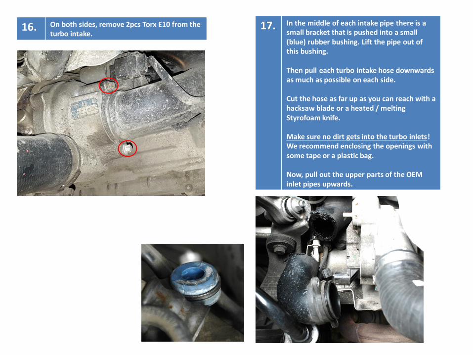
16. On both sides, remove 2pcs Torx E10 from the turbo intake.
17. In the middle of each intake pipe there is a small bracket that is pushed into a small (blue) rubber bushing. Lift the pipe out of this bushing.
Then pull each turbo intake hose downwards as much as possible on each side.
Cut the hose as far up as you can reach with a hacksaw blade or a heated / melting Styrofoam knife.
Make sure no dirt gets into the turbo inlets! We recommend enclosing the openings with some tape or a plastic bag.
Now, pull out the upper parts of the OEM inlet pipes upwards.

18. The breather check valve needs to be removed from the OEM intake pipe and then installed in the do88 performance intake hose.
Very slowly heat the top of the plastic around the area marked on the photo with a heating gun. This will melt the glue so the valve can be removed. It should fall off quite easily when the glue is hot enough.
19. The plastic flange needs to be grinded down to about 1mm high. Otherwise it wont fit inside the silicone hose. Make sure the valve is free of dirt after you have grinded the valve.
Do not install this in the silicone intake hose yet.

21. Now it is time to install the silicone turbo intake hoses on the car. With the help of a friend, push the hose downwards from the engine compartment while your friend pulls it down from the wheel housing.
It is a very tight fit to install these hoses. Make sure the hoses are not pushing on something that might be hurt. If so, remove the hose and “push” that area of the hose in order to slightly deform the steel wire within the hose and thereby allowing more clearance. This will not disturb the airflow.
20. To allow more clearance for the silicone turbo intake hoses you need to bend the brackets for the OEM intake pipes.
Bend the brackets downwards about 10mm. Do this on both sides.

22. Carefully install the included O-rings on the VGT adaptors as shown below.
23. Install the VGT adaptors onto the turbo chargers with the included M6 screws. Connect the do88 intake hoses and tighten them with the included hose clamps.
24. To be able to install the VGT protection cover on the left side, the plastic cover needs to be trimmed. See photos. Install it on the car with the included Zip Tie.

25. Install the breather check valve you modified in “Step 19”. Fasten it with the included hose clamp.
26. Install all other parts in reverse order.