Installation Instruction Book -...
16
NORTHLAND designer and master series INSTALLATION INSTRUCTIONS
Transcript of Installation Instruction Book -...
NORTHLAND designer and
master series
INSTALLATIONINSTRUCTIONS

2
TOOL LISTPhillips screwdriver PliersFlat blade screwdriver Adjustable wrench1/4" hexhead nutdriver 1/4" open end wrenchLevel Utility knifeDrill and Drill Bit (#6 - .204) Tape measure
UNPACKING:Check Cabinet and Power Module for freight damage.
This cabinet was carefully packed and thoroughly inspected before leaving our plant.Responsibility for its safe delivery was assumed by the carrier upon acceptance of the shipment.Claims for loss or damage sustained in transit must be made on the carrier as follows:
Exterior damage: Make thorough damage notation on your delivery receipt and have driveracknowledge by signature and date. Send a written request for an inspectionreport from carrier. Include the name of carrier representative and the date the inspectionwas requested. Retain inspection report and receipt for filing of the claim.
Concealed damage: This must be reported to the carrier within fifteen days. Obtain inspectionreport from the carrier. Retain the inspection report for filing of the claim.DO NOT RETURN DAMAGED MERCHANDISE TO MANUFACTURER- FILE THECLAIM WITH THE CARRIER.
Protect kitchen floor. Remove all packing materials from cabinet and if there was no freight damage destroycartoning, plastic bags and any exterior wrapping material immediately after the refrigerator is unpacked. Childrenshould never use these items for play. Remove all staples from the carton. Staples can cause severe cuts anddestroy finishes if they come in contact with other appliances or furniture. Carefully read and follow the child safetyprecautions in the pamphlet enclosed with your new refrigerator. It is published by the Association of HomeAppliance Manufacturers.Leveling Legs are mounted on the bottom of the cabinet. Adjust Leveling Legs to approximate desired height. DoNOT extend Legs more than 41/4" out from BOTTOM OF CABINET or they will not be secure.NOTE: Front legs have choice of two locations. This enables installer to recess kick area to more closelyapproximate kick depth of various style cabinetry. It is important, therefore, to exercise caution to avoid “tipping”the product and to secure product carefully.
Before you begin - Read these instructions completely and carefully.IMPORTANT - Save these instructions for local inspector's use.IMPORTANT - OBSERVE ALL GOVERNING CODES AND ORDINANCES.Note to Installer - Be sure to leave these instructions with the Consumer.Note to Consumer - Keep these instructions with your Use and Care Book for future reference.
CONTENTS:
TOOL LIST & UNPACKING INSTRUCTIONS................................................................................ 2PRE-INSTALLATION INSTRUCTIONS....................................................................................... 3,4INSTALLATION INSTRUCTIONS .................................................................................................. 5INSTALLING TWO UNITS SIDE BY SIDE ..................................................................................... 6KICK PLATE INSTALLATION ........................................................................................................ 6MODULE INSTALLATION ........................................................................................................... 7,8ICE MAKER WATER VALVE INSTALLATION ............................................................................... 9LOUVERED GRILL ASSEMBLY .................................................................................................. 10HINGE AND GASKET ADJUSTMENT ......................................................................................... 11CUSTOM DOOR PANELS ........................................................................................................... 12CUSTOM GRILL PANELS............................................................................................................ 13REMOVING PROTECTIVE FILM FROM PANELS ...................................................................... 13"TRIMLESS" DOOR / GRILL PANELS ......................................................................................... 14SIDE PANEL INSTALLATIONS.................................................................................................... 15INSTALLATION CHECKS / ERRORS .......................................................................................... 16

3
Model A
For seriesstarting with
(D), (G),or (W)
( ) 18R 171⁄2( ) 18FI 171⁄2( ) 18TI 171⁄2( ) 18MTI 171⁄2( ) 24R 231⁄2( ) 24FI 231⁄2( ) 24TI 231⁄2( ) 24MTI 231⁄2( ) 30R 291⁄2( ) 30FI 291⁄2( ) 30TI 291⁄2( ) 30MTI 291⁄2( ) 36R 351⁄2( ) 36FI 351⁄2( ) 36TI 351⁄2( ) 36MTI 351⁄2( ) 36SI 351⁄2( ) 36XI 351⁄2( ) 36MXI 351⁄2( ) 42SI 411⁄2( ) 42XI 411⁄2( ) 48SI 471⁄2( ) 48XI 471⁄2( ) 72RF 711⁄2
20min. (typ)* see note
below
Ice MakerTubing
781/2min.(typ)
22
A
22
24
78"approx.
Receptacle must be placed inthis location for 18" Models
85871/2
✛
Floor under Product MUST be at or above the same level as the surrounding FINISHED floor, for ease of installationand removal.
ELECTRICAL: Provide 115 Volt, 60 Cycle, Single Phase, 15 Amp, AC Receptacle. It is recommended that a separate circuit, servingonly this appliance, be provided. Two (2) units side by side, require separate circuits, except 72RF.
PLUMBING: Ice Maker water supply line (1⁄4" O.D. Copper Tubing) to come up the rear of rough-in opening approximately 78" offthe floor depending on height adjustment. Tubing should then pass around right side of module (left for Right-Hand-Freezer Side x Side units) and around the front to the solenoid valve (see Installation Instructions provided with theunit).
* For special Right-Hand-Freezer Side x Side Models, place electrical receptacle in rear wall at least 781/2" high and at least 20" from (right side) of rough-in.
IMPORTANTFor installation under a cabinet or soffit, a 3"space should be provided above the PowerModule (as shown on left). Use a removablepanel so that the Module can be installed orremoved easily without disturbing the lowercabinet.Note: Rough-in height (85" to 871⁄2").
**NOTEIf no overhead cabinet or soffit is present,you must cover the top of the rough openingwith at least 1⁄2" plywood.
Roug
h-In
Wid
th
8285
1/2
24
A A
85871⁄2
ROUGH-IN DETAIL FOR (1) UNITROUGH-IN WIDTH = “A”
ROUGH-IN DETAIL FOR (2) UNITSPLACED SIDE BY SIDE
ROUGH-IN WIDTH = “A” + “A” + 1⁄2"
PRE-INSTALLATION INSTRUCTIONS
*
*
85to
871⁄2
OVERHEAD CABINETOR SOFFIT OR**1/2 PLYWOOD
3/4 x 3 REMOVABLEPANEL
3 Min.
GRILLE
POWER MODULE
ModelNumber A
4
1" Min.Filler
Cabinet Outline
A
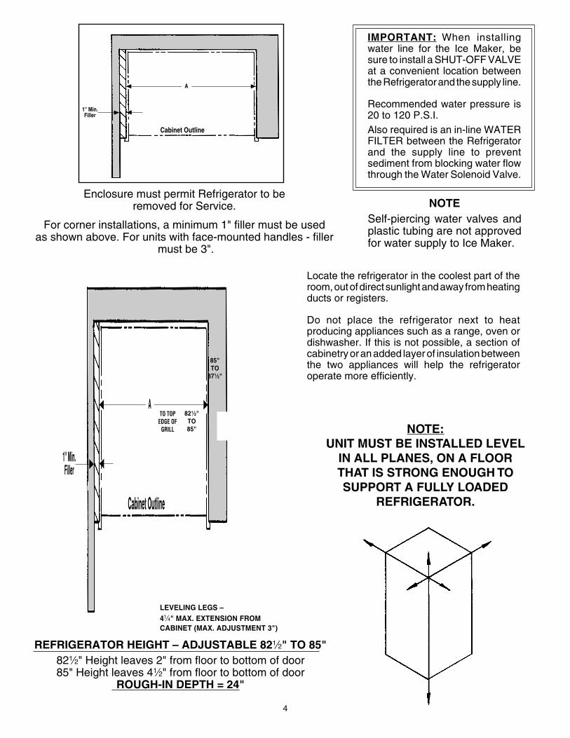
IMPORTANT: When installingwater line for the Ice Maker, besure to install a SHUT-OFF VALVEat a convenient location betweenthe Refrigerator and the supply line.
Recommended water pressure is20 to 120 P.S.I.Also required is an in-line WATERFILTER between the Refrigeratorand the supply line to preventsediment from blocking water flowthrough the Water Solenoid Valve.
NOTESelf-piercing water valves andplastic tubing are not approvedfor water supply to Ice Maker.
Enclosure must permit Refrigerator to beremoved for Service.
For corner installations, a minimum 1" filler must be usedas shown above. For units with face-mounted handles - filler
must be 3".
1" Min.Filler
Cabinet Outline
A
LEVELING LEGS –41⁄4" MAX. EXTENSION FROMCABINET (MAX. ADJUSTMENT 3")
TO TOPEDGE OF
GRILL NOTE:UNIT MUST BE INSTALLED LEVEL
IN ALL PLANES, ON A FLOORTHAT IS STRONG ENOUGH TOSUPPORT A FULLY LOADED
REFRIGERATOR.
REFRIGERATOR HEIGHT – ADJUSTABLE 821⁄2" TO 85"821⁄2" Height leaves 2" from floor to bottom of door85" Height leaves 41⁄2" from floor to bottom of door
ROUGH-IN DEPTH = 24"
821⁄2"TO85"
85"TO
871⁄2"
Locate the refrigerator in the coolest part of theroom, out of direct sunlight and away from heatingducts or registers.
Do not place the refrigerator next to heatproducing appliances such as a range, oven ordishwasher. If this is not possible, a section ofcabinetry or an added layer of insulation betweenthe two appliances will help the refrigeratoroperate more efficiently.
5
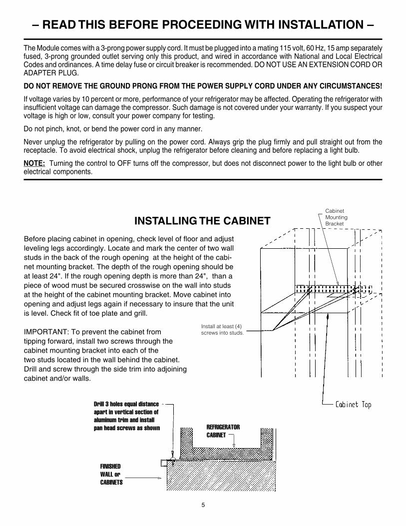
Before placing cabinet in opening, check level of floor and adjustleveling legs accordingly. Locate and mark the center of two wallstuds in the back of the rough opening at the height of the cabi-net mounting bracket. The depth of the rough opening should beat least 24". If the rough opening depth is more than 24", than apiece of wood must be secured crosswise on the wall into studsat the height of the cabinet mounting bracket. Move cabinet intoopening and adjust legs again if necessary to insure that the unitis level. Check fit of toe plate and grill.
IMPORTANT: To prevent the cabinet fromtipping forward, install two screws through thecabinet mounting bracket into each of thetwo studs located in the wall behind the cabinet.Drill and screw through the side trim into adjoiningcabinet and/or walls.
– READ THIS BEFORE PROCEEDING WITH INSTALLATION –
The Module comes with a 3-prong power supply cord. It must be plugged into a mating 115 volt, 60 Hz, 15 amp separatelyfused, 3-prong grounded outlet serving only this product, and wired in accordance with National and Local ElectricalCodes and ordinances. A time delay fuse or circuit breaker is recommended. DO NOT USE AN EXTENSION CORD ORADAPTER PLUG.
DO NOT REMOVE THE GROUND PRONG FROM THE POWER SUPPLY CORD UNDER ANY CIRCUMSTANCES!
If voltage varies by 10 percent or more, performance of your refrigerator may be affected. Operating the refrigerator withinsufficient voltage can damage the compressor. Such damage is not covered under your warranty. If you suspect yourvoltage is high or low, consult your power company for testing.
Do not pinch, knot, or bend the power cord in any manner.
Never unplug the refrigerator by pulling on the power cord. Always grip the plug firmly and pull straight out from thereceptacle. To avoid electrical shock, unplug the refrigerator before cleaning and before replacing a light bulb.
NOTE: Turning the control to OFF turns off the compressor, but does not disconnect power to the light bulb or otherelectrical components.
INSTALLING THE CABINETCabinetMountingBracket
Drill 3 holes equal distanceapart in vertical section ofaluminum trim and installpan head screws as shown
FINISHEDWALL orCABINETS
REFRIGERATORCABINET
Install at least (4)screws into studs.
6
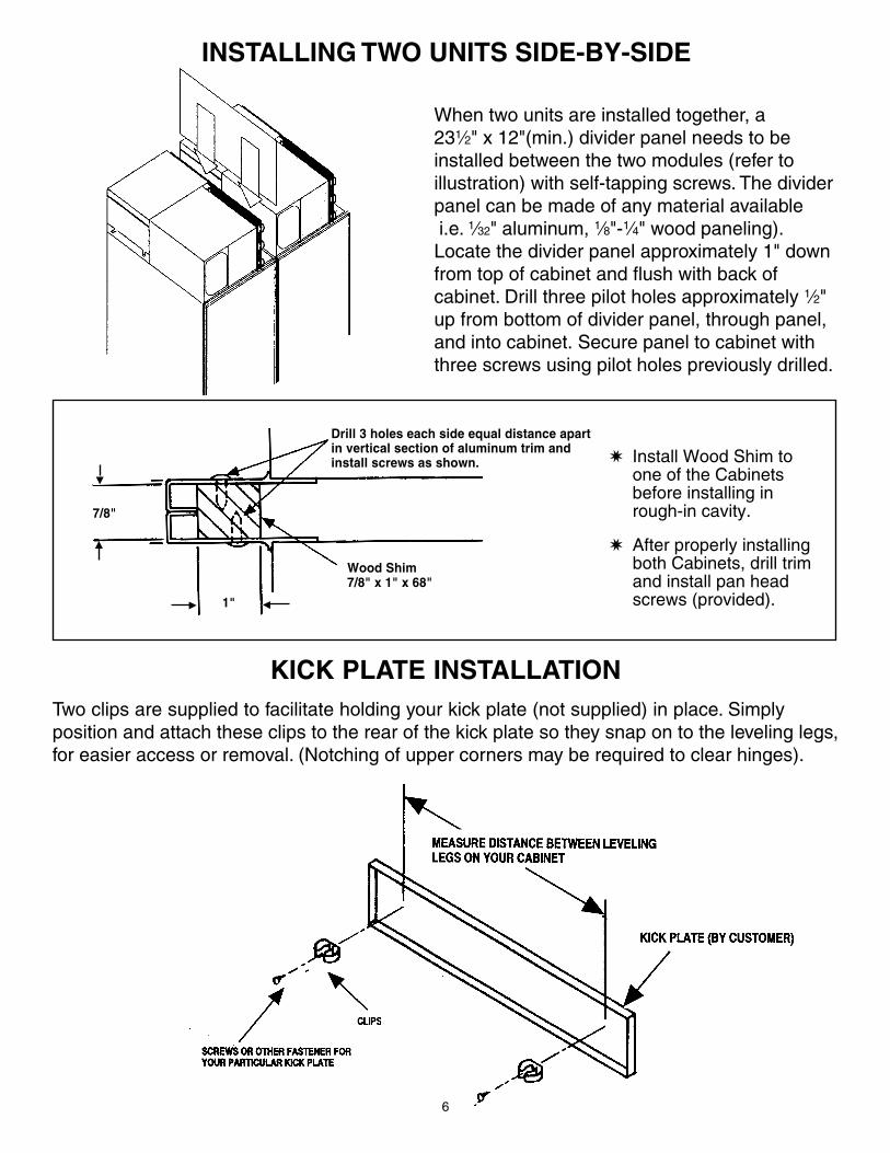
Drill 3 holes each side equal distance apartin vertical section of aluminum trim andinstall screws as shown.
Wood Shim7/8" x 1" x 68"
7/8"
1"G F
E
D
✷ Install Wood Shim toone of the Cabinetsbefore installing inrough-in cavity.
✷ After properly installingboth Cabinets, drill trimand install pan headscrews (provided).
When two units are installed together, a231⁄2" x 12"(min.) divider panel needs to beinstalled between the two modules (refer toillustration) with self-tapping screws. The dividerpanel can be made of any material available i.e. 1⁄32" aluminum, 1⁄8"-1⁄4" wood paneling).Locate the divider panel approximately 1" downfrom top of cabinet and flush with back ofcabinet. Drill three pilot holes approximately 1⁄2"up from bottom of divider panel, through panel,and into cabinet. Secure panel to cabinet withthree screws using pilot holes previously drilled.
INSTALLING TWO UNITS SIDE-BY-SIDE
KICK PLATE INSTALLATIONTwo clips are supplied to facilitate holding your kick plate (not supplied) in place. Simplyposition and attach these clips to the rear of the kick plate so they snap on to the leveling legs,for easier access or removal. (Notching of upper corners may be required to clear hinges).
7
IMPORTANT:Re-check Cabinet installation for:✷ Proper space left for Grill installation.✷ Cabinet levelness.✷ Door opening and closing appearance.✷ SAFETY … To prevent unit from tipping forward:
> Are screws installed securely through front Trim into adjoining cabinetry and/or walls?> Is Cabinet mounting bracket secured to wall studs?
After above checks have been made, proceed with refrigeration installation.
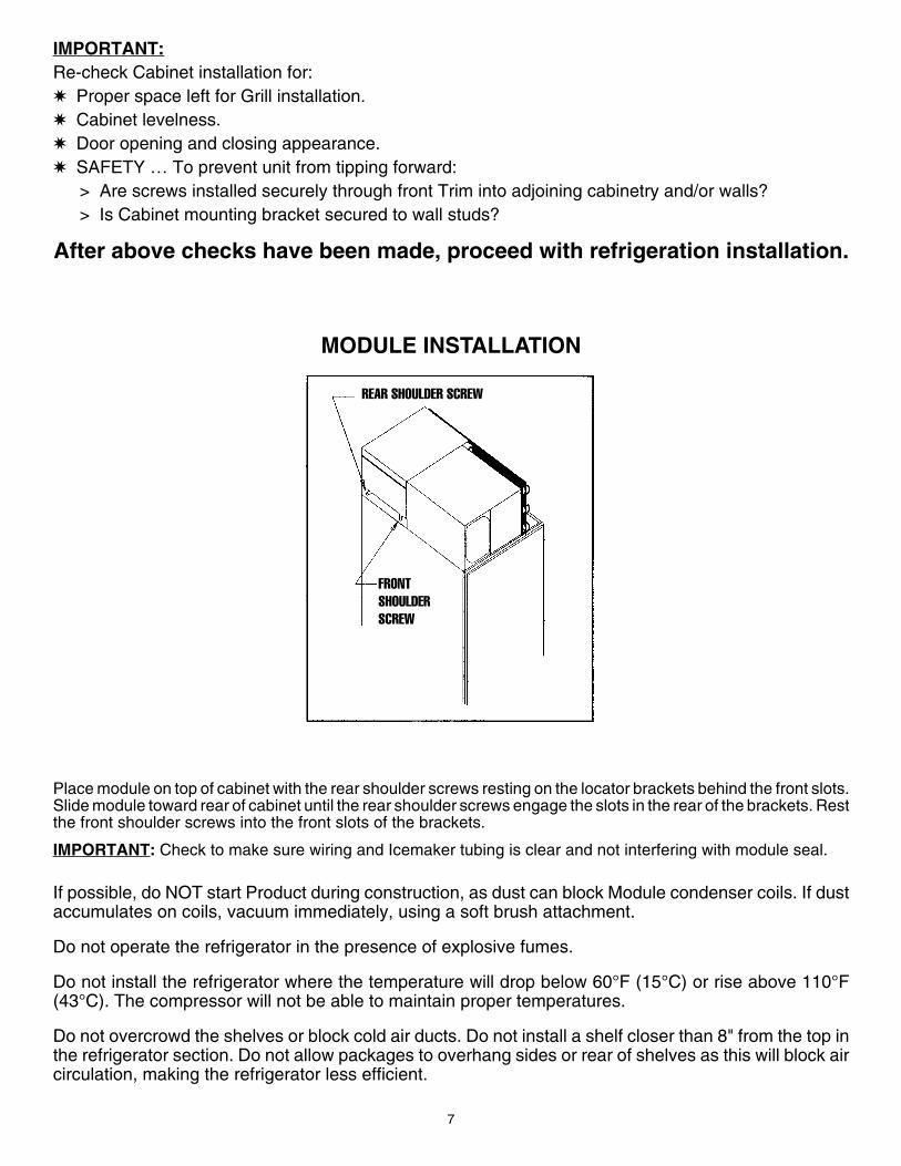
MODULE INSTALLATION
Place module on top of cabinet with the rear shoulder screws resting on the locator brackets behind the front slots.Slide module toward rear of cabinet until the rear shoulder screws engage the slots in the rear of the brackets. Restthe front shoulder screws into the front slots of the brackets.
IMPORTANT: Check to make sure wiring and Icemaker tubing is clear and not interfering with module seal.
If possible, do NOT start Product during construction, as dust can block Module condenser coils. If dustaccumulates on coils, vacuum immediately, using a soft brush attachment.
Do not operate the refrigerator in the presence of explosive fumes.
Do not install the refrigerator where the temperature will drop below 60°F (15°C) or rise above 110°F(43°C). The compressor will not be able to maintain proper temperatures.
Do not overcrowd the shelves or block cold air ducts. Do not install a shelf closer than 8" from the top inthe refrigerator section. Do not allow packages to overhang sides or rear of shelves as this will block aircirculation, making the refrigerator less efficient.
REAR SHOULDER SCREW
FRONTSHOULDERSCREW
8
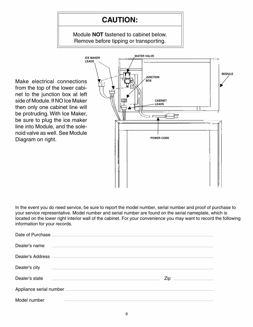
CAUTION:
Module NOT fastened to cabinet below.Remove before tipping or transporting.
Make electrical connectionsfrom the top of the lower cabi-net to the junction box at leftside of Module. If NO Ice Makerthen only one cabinet line willbe protruding. With Ice Maker,be sure to plug the ice makerline into Module, and the sole-noid valve as well. See ModuleDiagram on right.
E
E
E
E
WATER VALVE
MODULEJUNCTIONBOX
POWER CORD
ICE MAKERLEADS
CABINETLEADS
In the event you do need service, be sure to report the model number, serial number and proof of purchase toyour service representative. Model number and serial number are found on the serial nameplate, which islocated on the lower right interior wall of the cabinet. For your convenience you may want to record the followinginformation for your records.
Date of Purchase
Dealer's name
Dealer's Address
Dealer's city
Dealer's state Zip
Appliance serial number
Model number
E
E
E
9
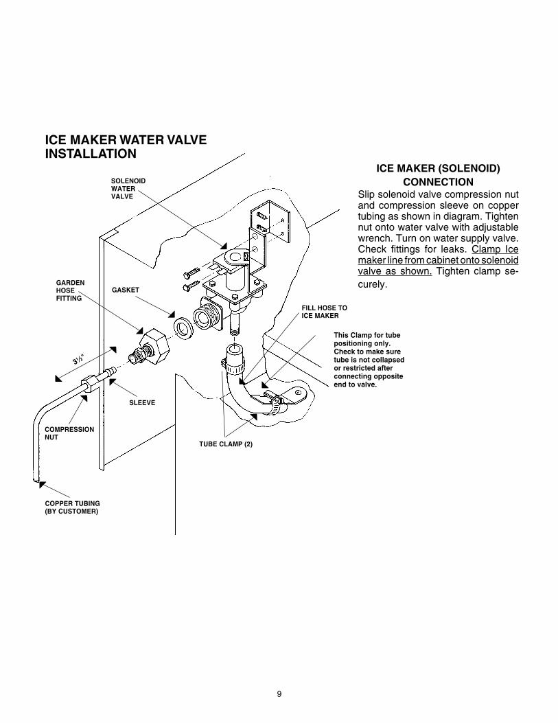
ICE MAKER WATER VALVEINSTALLATION
ICE MAKER (SOLENOID)CONNECTION
Slip solenoid valve compression nutand compression sleeve on coppertubing as shown in diagram. Tightennut onto water valve with adjustablewrench. Turn on water supply valve.Check fittings for leaks. Clamp Icemaker line from cabinet onto solenoidvalve as shown. Tighten clamp se-curely.
Z
Z
Z
X
X
X
X
X
X X
X
SOLENOIDWATERVALVE
GARDENHOSEFITTING
GASKET
SLEEVE
COMPRESSIONNUT
COPPER TUBING(BY CUSTOMER)
TUBE CLAMP (2)
FILL HOSE TOICE MAKER
This Clamp for tubepositioning only.Check to make suretube is not collapsedor restricted afterconnecting oppositeend to valve.
31 ⁄2"
10
LOUV
ERED
GRI
LL A
SSEM
BLY
EDGE
OF C
ABINE
T
GRILL
TOP T
RIM
SEE N
OTE #
2
BOTT
OM O
F GRIL
L SHO
WN BE
HIND T
OP TR
IM.
SEE N
OTE #
4.
CABIN
ET TO
P TRIM
.
MOUN
TING B
RACK
ETS
(91180
-000)
#8-5/8
P.H. S
CREW
. SE
E NO
TE #1
.
INSTR
UCTIO
NS FO
R INS
TALL
ING GR
ILL BR
ACKE
TS.
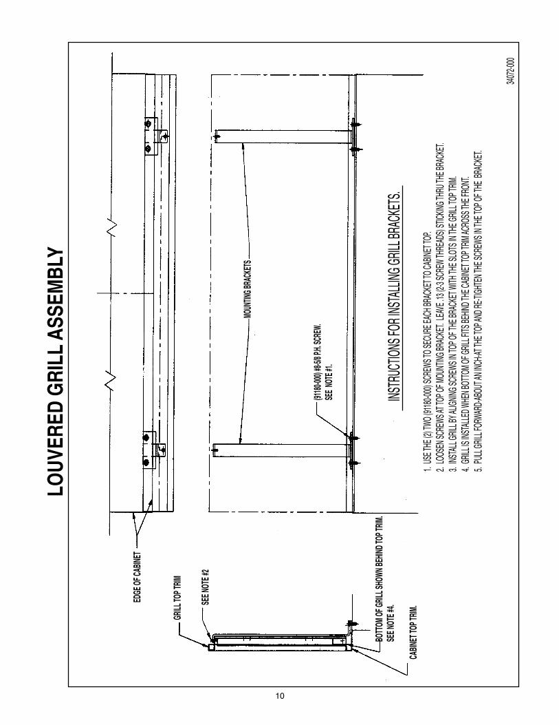
1. US
E THE
(2) T
WO (9
1180-0
00) S
CREW
S TO S
ECUR
E EAC
H BRA
CKET
TO CA
BINET
TOP.
2. LO
OSEN
SCRE
WS AT
TOP O
F MOU
NTING
BRAC
KET.
LEAV
E .13
(2-3
SCRE
W TH
READ
S) ST
ICKING
THRU
THE B
RACK
ET.
3. IN
STAL
L GRIL
L BY A
LIGNIN
G SCR
EWS I
N TOP
OF TH
E BRA
CKET
WITH
THE S
LOTS
IN TH
E GRIL
L TOP
TRIM
.4.
GRILL
IS IN
STAL
LED W
HEN B
OTTO
M OF
GRILL
FITS
BEHIN
D THE
CABIN
ET TO
P TRIM
ACRO
SS TH
E FRO
NT.
5. PU
LL GR
ILL FO
RWAR
D-ABO
UT AN
INCH
-AT TH
E TOP
AND R
E-TIGH
TEN T
HE SC
REWS
IN TH
E TOP
OF TH
E BR
ACKE
T.
3407
2-000

11
To expose concealed door hinge screws, first remove handle trim. Then slide trim over hingetoward handle side. If your unit requires Door Panels, see "CUSTOM DOOR PANEL", section onpage 12.
All hinge sections attached to DOORS, adjust left or right. Top and Bottom Cabinet Hinges are alsoadjustable in and out.
HINGE AND GASKETADJUSTMENT
It is possible that doors may become out ofadjustment in shipment. See diagram on right.
If product is installed slightly “out of level”,doors may not line up properly. Check thisBEFORE adjusting hinges.
NOTE: Door gaskets occasionally compressin shipment. If gasket does not seal all around,warm slightly with a hair dryer and pull outwardsoftly until magnet in gasket seals againstcabinet.
MASTER SERIES UNITS
To expose concealed door hingescrews, remove plug buttons ifpresent. All hinge sections attachedto Doors adjust left or right. Top andBottom Cabinet Hinges are alsoadjustable in and out. See diagram(shown without cabinet trim).
ADJUSTABLESCREW
EDGE OFDOOR TRIM
DOOR
CABINET

12
CUSTOM DOOR PANELS
Northland Designer Series Built-In design allows you to insert decorative material on the doorsof your refrigerator/freezer. If a panel thinner than 1⁄4" is being used, we recommend a filler beinserted behind it for a proper fit, as frames are designed to accept up to 1⁄4" material. If a raisedpanel is used, route edges to fit the frame.
CAUTION: Door Panels must not exceed 50 lbs. Panels weighing more than 50 lbs. may causeproduct damage. We recommend that the door load (panel and food) not exceed 90 lbs.
NOTE: Do not use glass, mirrors, granite, thick wood or similar heavy materials for panels.
✷ Remove Screws and Handle.
✷ Slide Custom Panel into position indoor Trim opening.
✷ Do ALL doors.
✷ Do not replace Handle until Hinge andGasket adjustments have been made ifnecessary. (See page 11.)
✷ Replace Handle and Screws and installPlastic Screw Caps provided.
MODEL DOOR PANEL SIZESNUMBER
Refrigerator Freezer Second freezerdoor door door
For series A B C D C Dstarting with
(D), (G),or (W)
( ) 18R 68 151⁄2( ) 18FI 68 151⁄2( ) 18TI 451⁄8 151⁄2 221⁄4 151⁄2( ) 18MTI 551⁄2 151⁄2 117⁄8 151⁄2( ) 24R 68 211⁄2( ) 24FI 68 211⁄2( ) 24TI 451⁄8 211⁄2 221⁄4 211⁄2( ) 24MTI 551⁄2 211⁄2 117⁄8 211⁄2( ) 30R 68 271⁄2( ) 30FI 68 271⁄2( ) 30TI 451⁄8 271⁄2 221⁄4 271⁄2( ) 30MTI 551⁄2 271⁄2 117⁄8 271⁄2( ) 36R 68 331⁄2( ) 36FI 68 331⁄2( ) 36TI 451⁄8 331⁄2 221⁄4 331⁄2( ) 36MTI 551⁄2 331⁄2 117⁄8 331⁄2( ) 36SI 68 17 68 151⁄2( ) 36XI 68 17 221⁄4 151⁄2 451⁄8 151⁄2( ) 36MXI 68 17 221⁄4 151⁄2 451⁄8 151⁄2( ) 42SI 68 211⁄2 68 17( ) 42XI 68 211⁄2 221⁄4 17 451⁄8 17( ) 48SI 68 271⁄2 68 17( ) 48XI 68 271⁄2 221⁄4 17 451⁄8 17
Hei
ght
Hei
ght
Hei
ght
Wid
th
Wid
th
Wid
th
Note:All center hinged doors, cannot exceed1/2" in panel thickness from the doortrim face.
13
MODELNUMBER
For seriesstarting with
(D), (G),or (W)
( ) 18R 1413⁄16
( ) 18FI 1413⁄16
( ) 18TI 1413⁄16
( ) 18MTI 1413⁄16
( ) 24R 2013⁄16
( ) 24FI 2013⁄16
( ) 24TI 2013⁄16
( ) 24MTI 2013⁄16
( ) 30R 2613⁄16
( ) 30FI 2613⁄16
( ) 30TI 2613⁄16
( ) 30MTI 2613⁄16
( ) 36R 3213⁄16
( ) 36FI 3213⁄16
( ) 36TI 3213⁄16
( ) 36MTI 3213⁄16
( ) 36SI 3213⁄16
( ) 36XI 3213⁄16
( ) 36MXI 3213⁄16
( ) 42SI 3813⁄16
( ) 42XI 3813⁄16
( ) 48SI 4413⁄16
( ) 48XI 4413⁄16
Grill
pan
el w
idth
( hei
ght –
89 ⁄1
6")
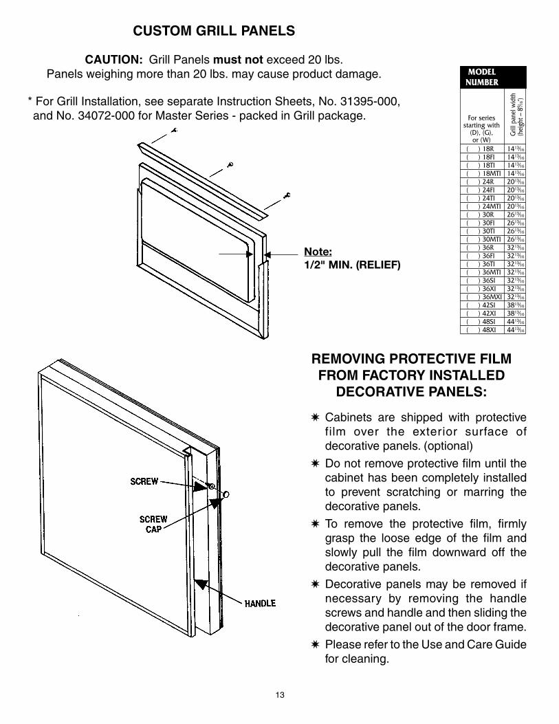
CUSTOM GRILL PANELS
CAUTION: Grill Panels must not exceed 20 lbs.Panels weighing more than 20 lbs. may cause product damage.
* For Grill Installation, see separate Instruction Sheets, No. 31395-000, and No. 34072-000 for Master Series - packed in Grill package.
Note:1/2" MIN. (RELIEF)
REMOVING PROTECTIVE FILMFROM FACTORY INSTALLED
DECORATIVE PANELS:
✷ Cabinets are shipped with protectivefilm over the exterior surface ofdecorative panels. (optional)
✷ Do not remove protective film until thecabinet has been completely installedto prevent scratching or marring thedecorative panels.
✷ To remove the protective film, firmlygrasp the loose edge of the film andslowly pull the film downward off thedecorative panels.
✷ Decorative panels may be removed ifnecessary by removing the handlescrews and handle and then sliding thedecorative panel out of the door frame.
✷ Please refer to the Use and Care Guidefor cleaning.
E
E
14
3/32
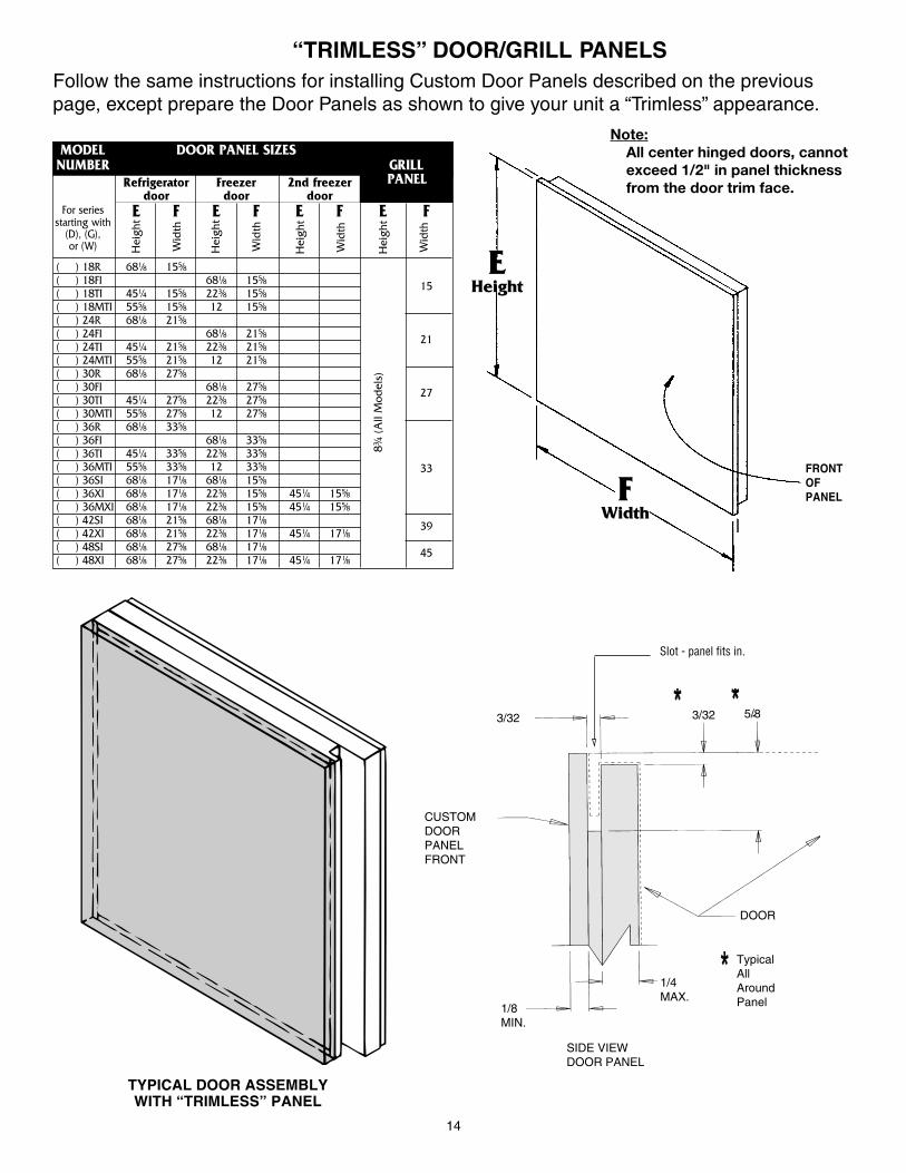
“TRIMLESS” DOOR/GRILL PANELSFollow the same instructions for installing Custom Door Panels described on the previouspage, except prepare the Door Panels as shown to give your unit a “Trimless” appearance.
MODEL DOOR PANEL SIZESNUMBER GRILL
Refrigerator Freezer 2nd freezer PANELdoor door door
For series E F E F E F E Fstarting with
(D), (G),or (W)
( ) 18R 681⁄8 155⁄8( ) 18FI 681⁄8 155⁄8( ) 18TI 451⁄4 155⁄8 223⁄8 155⁄8
15
( ) 18MTI 555⁄8 155⁄8 12 155⁄8( ) 24R 681⁄8 215⁄8( ) 24FI 681⁄8 215⁄8( ) 24TI 451⁄4 215⁄8 223⁄8 215⁄8
21
( ) 24MTI 555⁄8 215⁄8 12 215⁄8( ) 30R 681⁄8 275⁄8( ) 30FI 681⁄8 275⁄8( ) 30TI 451⁄4 275⁄8 223⁄8 275⁄8
27
( ) 30MTI 555⁄8 275⁄8 12 275⁄8( ) 36R 681⁄8 335⁄8( ) 36FI 681⁄8 335⁄8( ) 36TI 451⁄4 335⁄8 223⁄8 335⁄8( ) 36MTI 555⁄8 335⁄8 12 335⁄8( ) 36SI 681⁄8 171⁄8 681⁄8 155⁄8
33
( ) 36XI 681⁄8 171⁄8 223⁄8 155⁄8 451⁄4 155⁄8( ) 36MXI 681⁄8 171⁄8 223⁄8 155⁄8 451⁄4 155⁄8( ) 42SI 681⁄8 215⁄8 681⁄8 171⁄8( ) 42XI 681⁄8 215⁄8 223⁄8 171⁄8 451⁄4 171⁄8
39
( ) 48SI 681⁄8 275⁄8 681⁄8 171⁄8( ) 48XI 681⁄8 275⁄8 223⁄8 171⁄8 451⁄4 171⁄8
45
Hei
ght
Wid
th
Hei
ght
Wid
th
Hei
ght
Wid
th
Hei
ght
Wid
th
83 ⁄4 (
All
Mod
els)
FRONTOFPANEL
EHeight
FWidth
Note:All center hinged doors, cannotexceed 1/2" in panel thicknessfrom the door trim face.
TYPICAL DOOR ASSEMBLYWITH “TRIMLESS” PANEL
Slot - panel fits in.
1/8MIN.
SIDE VIEWDOOR PANEL
1/4MAX.
TypicalAllAroundPanel
CUSTOMDOORPANELFRONT
3/32 5/8
DOOR

15
IF FASTENING SIDE PANELS TOREFRIGERATOR:
A. Side panels should be 24"D(or 245⁄16"D when tucked into fronttrim).
B. Panel height to match installationheight.
C. Install side panels per drawings onright.
NOTE: To avoid damage to panels orflooring, raise panels slightly, to clearfloor when installing.
Drill three (3) holes equal distance apartin vertical section of aluminum trim andinstall pan head screws as shown.
Anchor side panel with screw as shown.Be sure screw used goes no more than1⁄2" deep into Product. Do NOTovertighten.
“A”
“B”
“C”
“D”
(TOP VIEW)1⁄4" THICK BATTENS
3⁄16" THICK BACK UP1⁄4" PLYWOOD/PANEL
3⁄16" THICK BATTENS
1⁄8" THICK BACK UP1⁄4" PLYWOOD/PANEL
245⁄16"
1⁄16" ROUT
1⁄2" PLYWOOD/PANEL23⁄16"
Drill (3) holes equal distance apart in vertical section of aluminum trim andinstall #6-x3⁄8 pan head screws as shown. (provided)
Attach side panel to cabinet with screws as shown. Screws must not penetratecabinet more than 1⁄2".
TYPICAL SIDE PANEL INSTALLATIONS
✛
✛ TYP.11⁄8
E
D
GF
G F
11⁄32"
METAL SIDE PANEL
24"(TYP. INSTALLATION OPENING)
5⁄16"
IF PRODUCT DOES NOT START WHEN PLUGGED IN, CHECK THE FOLLOWING:
1. Does light bulb go on when refrigerator door is opened? If NOT, check bulb, then …a. Is cord from lower cabinet plugged into module?b. Is power cord plugged in at receptacle?c. Is circuit breaker or fuse “on”? Check by plugging another electric device into outlet.
2. If light bulb DID go on when door is opened …a. Turn Defrost timer clockwise (might be in “Defrost”) until compressor starts.
3. If motor “hums”, but doesn’t start …a. Check for adequate line voltage at outlet.b. Module may have been transported or stored on side or upside down, causing
temporary displacement of motor oil. Let rest 12 to 24 hours, then plug in again.
TROUBLE SHOOTING
16
NORTHLAND KITCHEN APPLIANCE DIVISIONNorthland Corporation
P.O. Box 400Greenville, Michigan 48838-0400
34112-000
Installation Checks
• Cabinet Mounting Bracket must be installed correctly and anchored to prevent cabinet fromtipping forward.
• Rear of Module should be flush with the rear of the cabinet. Module should not extend beyondthe rear wall of the cabinet.
• Module should be engaged in the slots on the Module positioning brackets and seated on thefoam seal without air gaps. Module positioning brackets should not be removed.
• All wires from the lower cabinet to Module must be securely connected. If a problem issuspected, inspect both male and female plugs and insure that the terminals in the plug aresufficiently forward to engage.
• Cabinet must be level both side to side and front to back. All legs should rest firmly on thefloor. Cabinetry on both sides of the cabinet must be secure and level to prevent the cabinetfrom shifting when the doors are opened.
• Doors must not hit adjacent walls or counter tops.
• Gaskets must seal completely. If gaskets seal well, no further adjustments need to be made.
• On models with ice makers, check water connections for leaks. If water is not yet connected,the plastic water fill tube to the freezer compartment must either be attached to the solenoid orsealed to prevent air leaking into the cabinet.
• Brown and white wires should be connected to the solenoid. The remaining Molex connectorplugs into the Power Module.
Common Installation Errors
• Any air leaks between the module and the cabinet will affect the cabinet from operatingefficiently.
• The water supply line and electric outlet must be located in a manner that will not interfere withModule to cabinet alignment when the unit is pushed into place.
• Power cord to outlet sitting under the Power Module will create an air leak.
• Ice maker fill tube (plastic) not connected or loose creating a water and/or air leak.
• Plugs from cabinet not connected to ice maker and/or Power Module.
• Floor under product lower than finished floor making the unit inaccessible for service. Floorunder product must be strong enough to support weight of fully loaded refrigerator.
• No 3" removable panel above grill making the Power Module inaccessible for service.
• Product not anchored properly (to prevent tipping). Bracket not secured to rear wall studs orscrews through product side trim into adjoining cabinets or walls.