Installation Instruction and Owners Manual MAGNUM … · Installation Instruction and Owners Manual...
20
Installation Instruction and Owners Manual MAGNUM SALT/SAND SPREADERS Models: S1075P & S575P Form 1-918 R2 May 2010 Magnum Spreader reserves the right, under its continuing product improvement program, to change construction or design details, specifications and prices without notice or without incurring any obligation. © 2010 Printed in the U.S.A. Magnum Spreader 18513 Euclid Ave. • Cleveland, Ohio 44112-1084 Phone 486-1313 (Area Code 216) www.magnumspreaders.com S1075P S575P
Transcript of Installation Instruction and Owners Manual MAGNUM … · Installation Instruction and Owners Manual...

Installation Instruction and Owners ManualMAGNUM SALT/SAND SPREADERS
Models: S1075P & S575P
Form 1-918 R2May 2010
Magnum Spreader reserves the right, under its continuing product improvement program, to change construction or design details,specifications and prices without notice or without incurring any obligation.
© 2010 Printed in the U.S.A.
Magnum Spreader18513 Euclid Ave. • Cleveland, Ohio 44112-1084
Phone 486-1313 (Area Code 216)www.magnumspreaders.com
S1075P
S575P

TABLE OF CONTENTS
INTRODUCTION ................................................................................................. 1
VEHICLE REQUIREMENTS ................................................................................ 1
SAFETY GUIDELINES ........................................................................................ 2
S575P PARTS LIST ............................................................................................. 3
INSTALLING RECEIVER MOUNT MODEL: S575 .............................................. 4
S1075P PARTS LIST ........................................................................................... 5
S1075P R.D.R PARTS LIST ................................................................................ 6
ELECTRICAL INSTALLATION ............................................................................ 7
INSTALLING HINGE MOUNT 35500 .................................................................. 8
HINGE MOUNT 35500 PARTS LIST ................................................................... 9
INSTALLING FIXED MOUNT 35200 .................................................................. 10
FIXED MOUNT 35200 PARTS LIST ................................................................... 10
INSTALLING DUMP BED MOUNT 35300.......................................................... 11
DUMP BED MOUNT 35300 PARTS LIST .......................................................... 11
INSTALLING FLAT BED MOUNT 35400............................................................ 12
FLAT BED MOUNT 35400 PARTS LIST ............................................................ 12
SAND VIBRATOR KIT (OPTIONAL) .................................................................. 13
HOPPER SCREEN (OPTIONAL) ....................................................................... 14
FLOW GATE ASSEMBLY (OPTIONAL) ............................................................. 15
OPERATING THE SPREADER .......................................................................... 16
SPREADER MAINTENANCE ............................................................................. 17
TROUBLESHOOTING ........................................................................................ 17
WARRANTY INFORMATION.............................................................................. 18

INTRODUCTIONThis manual will assist you in the proper set-up, installation, and use of the MAGNUM series spreaders.
Please read and understand the contents of the manual completely (especially all safety information) before attempting anyprocedure contained herein.
The MAGNUM line of spreaders may be attached to many types of vehicles to suit different spreading needs.
The modular design allows for multiple mounting variations using the same spreader.
Our heavy-duty construction uses high quality steel, stainless steel or polyethylene along with industrial grade electrostaticpaint finishes so that maintenance is minimal.
Our high torque, direct drive motor powered by a state-of-the-art, variable speed, solid state electronic controller will providereliable power and control when spreading, even at extremely low temperatures.
Magnum Spreader reserves the right to make any changes or improve the design of any parts and not be obligated to makechanges on units previously sold.
VEHICLE REQUIREMENTSFOR MAGNUM SERIES SALT/ SAND SPREADER INSTALLATION
1.) For installation of S1075 series salt spreaders:
A.) Due to the size and capacity of these spreaders we recommend installation on full size trucks with a 3/4 Tonrating or higher.
B.) Stock mountings (“Hinged” or “Fixed”) are designed to be used only with full size pick-up trucks which haverear bumpers in good condition (top surface must be straight and relatively level with truck)
C.) If hinged mounting is desired, the truck’s bed rails must also be of good condition and stake pockets free foruse.
D.) If fixed mounting will be used, the tailgate must close and latch solidly
2.) For installation of S575 series salt spreaders:
A.) This product line can be installed on any vehicle with a class 3 hitch receiver that will accept a 2" square tubeand has a tongue weight rating of at least 500 lbs.
B.) If your vehicle is not factory equipped with a hitch, we recommend taking it to a reputable trailer hitch installationshop or your vehicles dealership.
C.) Reese and Draw-Tite offer a dual port hitch (DPS) with two round, downward angled receivers. A 5.75 cu. ft.MAGNUM spreader can be ordered to fit this system.
As with any vehicle accessory, please refer to you owners manual to verify that the GVWR (Gross Vehicular WeightRating) will not be exceeded, especially if this product will be used in conjunction with other mounted equipment. Ifequipment is mounted to vehicle with other than stock hardware or components, we the manufacturer cannot and willnot be held responsible for damages. Also, check your vehicle owner’s manual to be sure that the installation of “after-market” accessories will not void the manufacturers’ factory warranty.
(1)

SAFETY GUIDELINES
For you safety when the word WARNING is used, this refers to information that if not carefully followed could result in personalinjury or death.
The word CAUTION refers to a situation that could cause minor injury or damage to equipment.
WARNING – Before operating READ and UNDERSTAND this operators manual in its entirety.
WARNING – NEVER operate equipment while under the influence of alcohol, drugs, or medications that might impair yourjudgment and reaction time.
WARNING – NEVER allow children to operate equipment.ALWAYS CHECK AREAS to be spread to be sure no hazardous conditions or substances are present.ALWAYS INSPECT UNIT FOR DEFECTS: broken, bent, or worn parts, or weakened areas on spreader or mount.
WARNING – ALWAYS SHUT OFF vehicle power source before attaching, detaching, or servicing the equipment.
WARNING – ALWAYS MAKE SURE PERSONNEL ARE CLEAR of spread pattern when using equipment.
WARNING – NEVER EXCEED 45 M.P.H when loaded spreader is attached to vehicle. Braking distances and handlingcharacteristics may be impaired at greater speeds.
CAUTION – Never use wet materials or material with foreign debris. This unit is designed to handle clean, dry, free-flowingmaterial.
CAUTION - Never leave material in hopper for long periods of time. All ice melters are hygroscopic and will attract atmosphericmoisture and harden.
WARNING – INSPECT pins and bolts whenever attaching, detaching, and before travel. All factory installed bolts utilize locknuts however road and operational vibrations might loosen them.
WARNING – INSPECT unit periodically for defects. Parts that are broken, worn, or missing musts be replaced immediately.The unit or any part of it should NOT be altered in any way without prior written permission from the manufacturer.
WARNING – When using swing mount, NEVER swing spreader with material in hopper!.
WARNING – NEVER attempt to clear a jammed feed screw with the power on!
WARNING – NEVER place hands into hopper or around feed screw and spinner when power is on. Also, keep loose clothingand hair away from moving parts!
CAUTION – De-icing materials can be damaging to plant life and concrete. Know what you are spreading and where you arespreading it.
(2)
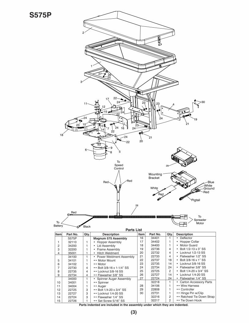
(3)
Item Part No. Qty. DescriptionS575P Magnum 575 Assembly
1 32110 1 • Hopper Assembly2 34200 1 • Lid Assembly3 32200 1 • Frame Assembly4 35001 1 • Hitch Weldment
34100 1 • Power Weldment Assembly5 34101 1 •• Motor Mount6 34102 1 •• Motor7 22730 4 •• Bolt 3/8-16 x 1-1/4” SS8 22735 4 •• Locknut 3/8-16 SS9 22734 4 •• Flawasher 3/8” SS
34000 1 • Spinner Auger Assembly10 34001 1 •• Spinner11 34004 1 •• Auger12 22725 3 •• Bolt 1/4-20 x 3/4” SS13 22727 3 •• Locknut 1/4-20 SS14 22724 3 •• Flawasher 1/4” SS15 22726 1 •• Set Screw 5/16” SS
Parts List
Parts indented are included in the assembly under which they are indented.
S575P
Item Part No. Qty. Description16 34401 1 • Deflector17 34402 1 • Hopper Collar18 34400 1 • Motor Guard19 22736 4 • Bolt 1/2-13 x 3” SS20 22732 4 • Locknut 1/2-13 SS21 22733 4 • Flatwasher 1/2” SS22 22737 18 • Bolt 3/8-16 x 1” SS23 22735 14 • Locknut 3/8-16 SS24 22734 24 • Flatwasher 3/8” SS25 22725 2 • Bolt 1/4-20 x 3/4” SS26 22727 14 • Locknut 1/4-20 SS27 22724 24 • Flatwasher 1/4” SS
32218 1 • Carton Accessory Parts28 34106 1 •• Wire Harness29 22808 1 •• Controller30 22731 1 •• Hinge Pin w/Clip
32216 2 •• Ratchest Tie Down Strap32217 2 •• Tie Down Hook
1
2
3
4
56
7
8
9
10
1112
1314
15
16
17
18
19
2021
22
23
24
252627
21
22
22
23
232324
24
24
24
24
2224
30
28
29
Red
Red
BlackTo
Battery
To SpeedControl
To Spreader
Motor
BlueWhiteGroundRed
White
Red
Pigtail
MountingBracket
Red

(4)
INSTALLING RECEIVER MOUNT MODEL: S575PThe MAGNUM S575p is a dedicated, Class 3, receiver (hitch) mount salt spreader. Prior to installation, be certain that thevehicle receiver is in good working order, is rated for at least a 500 lb. tongue load, and is fastened to the vehicle securely.
CAUTION - The spreader is a large heavy item that should be installed with an assistant. As with any new equipment installationread and understand all instructions prior to starting the job, and do not hurry through it. A correct installation now can savetime and money later.
1.) Using an assistant remove the spreader unit and all loose components from the packaging and set cover aside untilinstallation is complete. Retain original packaging for storage purposes.
2.) Locate the large hitch pin and cotter clip from the hardware package. Set these items aside, as they will be used laterduring the installation.
3.) Inspect the vehicles receiver tube and check for rust, dirt, or foreign debris that may have collected in it. If there are anyblockages clean with compressed air and a wire brush.
4.) Apply good quality grease to the inside of the receiver tube, this will prevent rusting and make the spreader easier toremove at the end of the season.
5.) The framework will have four 1/2-13 x 3” SS Bolts (20) already installed in the mounting holes for the stinger. Removethe 1/2-13 SS Locknuts (22) and 1/2” SS Flatwashers (21) and apply a light oil to the threads, this will make assemblyeasier; yet will not affect the locking properties of the safety nuts. Place the stinger over the bolts, replace the nuts andwashers and fully tighten. (Note: The mounting tube may be placed in either the raised or lowered position by flippingthe stinger over. This is owner preference) The DPS version is always installed with a downward angle for the tworound stingers.
6.) Lift the spreader unit upright (hopper opening facing up) with mounting tube pointed toward the truck.
7.) Slowly slide spreader mounting tube into the vehicles receiver until the through holes in receiver match through holesin spreader. (See note below)
8.) Insert the large hitch pin through the receiver tube and spreader mounting tube. Secure with the cotter clip.WARNING – The cotter clip must be in place for safe operation.
9.) Place the cover over the hopper and secure clamps on left and right sides.
NOTE: •The spreader mounting tube has 2 pre-punched hole sets to provide some adjustment when installing the unit.•Always use the hole set that places the unit closest to the vehicle but without touching it.
WARNING – Never attempt to drill new holes in the spreader mounting tube, contact your local trailer hitch supplierabout relocating or replacing you current hitch, if mounting problems occur.
10.) Use the Ratchet Tie Down Strap and Tie Down Hooks to tie spreader to vehicle frame to elininate any rocking of thespreader.
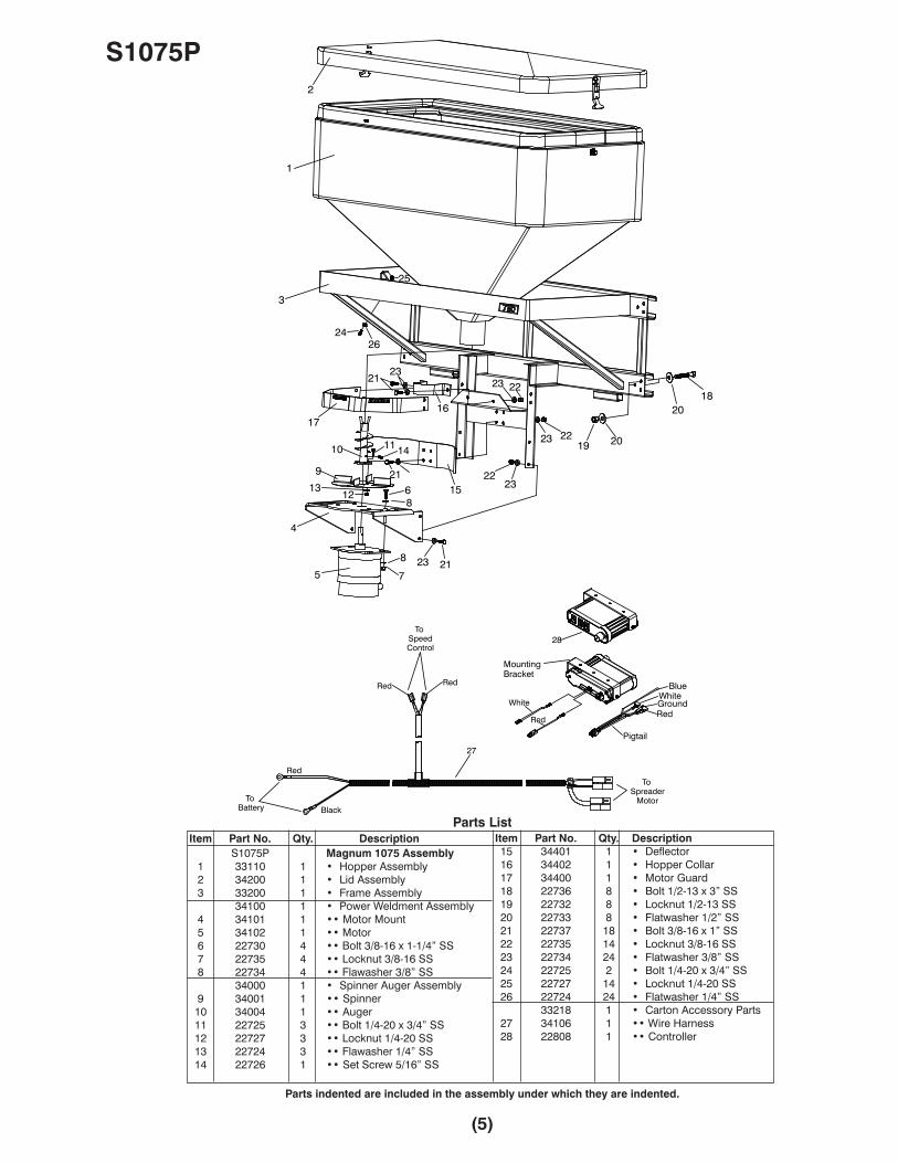
Item Part No. Qty. DescriptionS1075P Magnum 1075 Assembly
1 33110 1 • Hopper Assembly2 34200 1 • Lid Assembly3 33200 1 • Frame Assembly
34100 1 • Power Weldment Assembly4 34101 1 •• Motor Mount5 34102 1 •• Motor6 22730 4 •• Bolt 3/8-16 x 1-1/4” SS7 22735 4 •• Locknut 3/8-16 SS8 22734 4 •• Flawasher 3/8” SS
34000 1 • Spinner Auger Assembly9 34001 1 •• Spinner10 34004 1 •• Auger11 22725 3 •• Bolt 1/4-20 x 3/4” SS12 22727 3 •• Locknut 1/4-20 SS13 22724 3 •• Flawasher 1/4” SS14 22726 1 •• Set Screw 5/16” SS
Parts List
Parts indented are included in the assembly under which they are indented.
S1075P
(5)
Item Part No. Qty. Description15 34401 1 • Deflector16 34402 1 • Hopper Collar17 34400 1 • Motor Guard18 22736 8 • Bolt 1/2-13 x 3” SS19 22732 8 • Locknut 1/2-13 SS20 22733 8 • Flatwasher 1/2” SS21 22737 18 • Bolt 3/8-16 x 1” SS22 22735 14 • Locknut 3/8-16 SS23 22734 24 • Flatwasher 3/8” SS24 22725 2 • Bolt 1/4-20 x 3/4” SS25 22727 14 • Locknut 1/4-20 SS26 22724 24 • Flatwasher 1/4” SS
33218 1 • Carton Accessory Parts27 34106 1 •• Wire Harness28 22808 1 •• Controller
1
2
3
4
5
6
7
8
9
10 11
1213
14
15
1617
18
19
20
2122
23
24
25
26
8
20
21
21
22
22
23
23
23
23
27
28
Red
Red
BlackTo
Battery
To SpeedControl
To Spreader
Motor
BlueWhiteGroundRed
White
Red
Pigtail
MountingBracket
Red

S1075P R.D.R
(6)
Item Part No. Qty. Description33505 Magnum Assembly 1075P R.D.R
1 33111 1 • Hopper Assembly2 22729 6 •• Bolt 10-24 x 5/8” SS3 34407 2 •• Latch Hook4 34201 1 • Lid Assembly5 34408 2 •• Rubber Latch6 32200 1 • Frame Assembly
---------- 1 • Power Weldment Assembly7 34101 1 •• Motor Mount8 36402 1 •• Motor9 20029 4 •• Bolt 5/16-18 x 1-1/2” Gr. 210 20313 4 •• Locknut 5/16-1811 20352 8 •• Flatwasher 5/16”
36152 1 •• Spinner Hub12 36414 1 •• Spinner13 36151 1 •• Auger14 22727 3 •• Locknut 1/4-20 SS15 22724 3 •• Flawasher 1/4” SS16 22725 3 •• Bolt 1/4-20 x 3/4” SS17 22726 1 •• Set Screw 5/16” SS
Parts ListItem Part No. Qty. Description
18 34401 1 • Deflector19 34402 1 • Hopper Collar20 34400 1 • Motor Guard21 22737 14 • Bolt 3/8-16 x 1” SS22 22735 14 • Locknut 3/8-16 SS23 22734 28 • Flatwasher 3/8” SS
32216 1 • Ratchet Tie Down Strap32217 1 • Tie Down Hook34608 1 • Hardware Bag
24 22736 8 •• Bolt H 1/2-13 x 3” SS25 22732 8 •• Locknut 1/2-13 SS26 22733 16 •• Flatwasher 1/2” SS27 22731 1 • Hitch pin w/clip28 35010 1 • Hitch Weldment29 34106 1 • Wire Harness30 22808 1 • Controller
Parts indented are included in the assembly under which they are indented.
23
1
2
3
6
7
8
9
10
11
12
13
14
15
16
1718
19
2022
23
24
25
26 27
28
4
5
9
11
11
21
21
21
22
22
23
23
23
23
23
22
23
23
2426
26
30
Red
To SpeedControl
BlueWhiteGroundRed
White
Red
Pigtail
MountingBracket
Red
29
Red
BlackTo
Battery
To Spreader
Motor

ELECTRICAL INSTALLATIONFOR ALL MAGNUM SERIES SPREADERS
1.) Locate the wire harness and begin to route it from the rear of the vehicle to the front. The molded rubber plug indicatesthe rear of the harness, closest to the spreader. Use frame holes and frame supports as lashing points. Do not attachto fuel or brake lines. Avoid wire-runs along exhaust system or hot engine parts. Melting damage to the harness canoccur in the proximity of extreme heat.
2.) Mount the rubber plug under the rear bumper. Position this plug toward the center of the vehicle.
3.) Place the Harness portion that connects to the battery along the firewall and fender well, but do not connect yet.
4.) Drill a 1" diameter hole through the firewall. This hole will be used to route the controller portion of the harness into thevehicle. Before drilling always check to see what is on the other side.
5.) Push the controller portion of harness through the hole in the firewall that was previously drilled. NOTE: The controllerend will have 2 plugs on it, but only 1 plug can pass through the firewall at a time.
6.) Move to engine compartment. Connect power leads to battery: RED WIRE (+) positive, BLACK WIRE (-) negative. Coatthe connections with dielectric grease to prevent corrosion and build up. Check harness marked ‘battery’ for voltageby temporarily removing the red tape affixed to it.
7.) Connect the blue wire from pigtail to brake light. Connect white wire from pigtail to optional vibrator harness if equipped.Connect red wire on pigtail to a 12 volt keyed accessory. Connect black ground wire to ground. Connect white jumperwire to the back of the controller marked motor white wire. Connect red jumper wire to the back of the controllermarked battery red wire wire. The two red wires from the main connector can now be connected to the two jumperwires. (Note: wires will only connect one way) ANY ATTEMPT TO JOIN THE CONNECTORS IMPROPERLY, FOREXAMPLE MALE TO MALE, COULD SHORT OUT THE CONTROLLER.Misconnection resulting in a damaged controller is not covered by warranty.
8.) Select a suitable location to mount the controller. After mounting verify that the power switch is in the off position.
9.) Coil excess wire and use wire ties to secure it to a safe location.
10.) Mate the plug coming from the spreader unit to the plug previously installed under the rear bumper.
11.) Make sure that feed screw/spinner area of the spreader is clear of obstructions. Turn power on at the controller andverify that the spreader is operating in all modes. Looking down on the impeller from the rear of the vehicle, determinethat the impeller is turning counter-clockwise. Unit may now be operated.
12.) If you purchased an accessory hopper vibrator, use the drilling template to mount the motor on the outside of thehopper. On 5.75 cu. ft. units, the motor is mounted on the vehicle side hopper wall. On 10.75 spreaders the motor willmount on the rearmost side of the hopper. An on/off auxiliary toggle switch is mounted within easy access of the driverinside the vehicle to break the positive lead to the motor. The negative wire is continuous to the vibrator motor.
(7)

INSTALLING HINGED MOUNT MODEL: (35500)This section covers the installation of a Magnum 1075 on a vehicle as hinged mount. CAUTION – This salt spreader is a heavy, bulkyitem that should be installed with assistance.
As with any new equipment installation read and understand all instructions prior to starting the job, and do not hurry through it. A correctinstallation now can save time and money later.
1.) Using an assistant, remove the spreader unit and all loose components from the packaging and set the cover aside until installationis complete. Retain original packaging for storage purposes during the “off” season.
2.) Find the Driver and Passenger Side Bed Rail Brackets (3 & 4) and center along the top of each bed rail with the slot over the trucksstake pocket. Attach using 1/2-13 x 3” Bolt (11), 1/2” Flatwasher (14) and 1/2-13 Toggle Wing (2) through the slot and stake pocket.Hand tighten both sides.
3.) Slide the Driver and Passenger Side Bed Rail Brackets (3 & 4) out toward the back of the truck. This will assist in determining thecorrect distance for mounting the spreader away from the tailgate, approximately 2" of clearance.
4.) Place the Driver and Passenger Side Bumper Plates (1 & 2) on the bumper. Slide the Hinge Pin (5) through the bed rail bracket andinto the socket on the bumper plates. Lower the tailgate to check that it will still function properly.
5.) Before drilling any holes double check that the Driver and Passenger Side Bumper Plates (1 & 2) are parallel and level with each other.Use a square or level to check that the Hinge Pin (5) is vertical and square to the Driver and Passenger Side Bumper Plates (1 & 2) andDriver and Passenger Side Bed Rail Brackets (3 & 4). NOTE: The driver and passenger side mounting components are mirror imagesof each other, and each side must be installed in exactly the same manor for the spreader to open and close properly. After everythinghas been checked, remove the Hinge Pins (5) and keep them handy, they will be used shortly. Tighten the toggle bolts in the Driverand Passenger Side Bed Rail Brackets (3 & 4). Do not exceed 30 Ft. lbs. of torque.
6.) If possible clamp the Driver and Passenger Side Bumper Plates (1 & 2) to the bumper and use them as guide for drilling, if that is notpossible use a center punch or scribe to mark the holes. Mount the plate using 3/8-16 x 1” Screws (8), 3/8” Flatwashers (13), and3/8-16 Locknuts (12) that are included in the swing mount hardware package.
7.) Install the two Hinge Channel (6) on the driver side (left) of the frame. Install the two Locking Arm Assemblies (7) on the passengerside (right). Install the Hinge Pin (5) on the passenger side and lock it in place in the bumper plate base with the 1/4” Snap Pin (16)provided. Pull back the two latches on the passenger Locking Arm Assemblies (7) to their open/locked position. With an assistant, liftthe spreader upright (hopper opening face up) and set it on the newly installed bumper plates. With the assistant holding thespreader, slide the “C” channels outward from the main frame so that the Hinge Channel (6) on the driver’s side line up to allowinstallation of the driver side Hinge Pin (5). Drop the Hinge Pin (5) through to the Driver Side Bumper Plate (1) and lock it in place withthe other 1/4” Snap Pin (16). When the “U” shaped ends are placed around the passenger side Hinge Pin (5), release the spring-loaded latches to the closed position and push downward to lock. The spreader should now be supporting itself.
8.) Thread 3/8-16 x 3” Bolts (10) into the bottom of the driver side bed rail bracket but do not tighten. Place Bolt Tip Cover (17) on the endof each bolt. Tighten bolts firmly. NOTE: If Bolt Tip Covers (17) are not used, damage to vehicle paint may occur. Repeat this step onthe passenger side.
9.) Measure to ensure that the spreader is centered on the vehicle and is supported by the mounting before proceeding. There willbe 6 pre-punched holes on each side of the spreader frame, 3 on the on the upper “C” channel and 3 on the lower. Use these holesas a guide and drill 3/8" Dia. through the adjustable “C” channels. Install 3/8-16 x 1-1/4” Bolt (9) with 3/8” Flatwashers (13) and3/8-16 Locknuts (12) in each hole.
10.) Open the passenger side latches and swing the spreader unit away from the truck to check for binding. If binding occurs it will becaused by one or both of 2 situations:
11.) The bolts holding down the Bumper Plates (1 & 2) are striking the frame support blocks. Remove spreader from mounting andreposition 1 bolt at a time until all are clear. New holes can be drilled if necessary.
12.) The Hinge Pins (5) are not properly lined up. Adjust Hinge Pins (5) one side at a time by loosening the bolts holding the Bed RailBracket (3 & 4) down and reposition the brackets slightly; this will in turn adjust the Hinge Pin (5).
Swinging to passenger side requires removal of driver side Hinge Pin (5). Make sure all bolts are tight.
13.) Secure the cord coming from the motor to the spreader frame and lower adjustable “C” channel with wire ties. Rout the cord out tothe pivot. This will take up the slack in the cord and still allow the spreader to swing. This can be changed at any time by simplyrouting the cord to the other side.
14.) The cover may now be installed and latched both sides. The spreader unit can be pivoted from either the driver or passenger side.
15.) WARNING – TO AVOID DAMAGING YOUR VEHICLE, NEVER ATTEMP TO SWING THE SPREADER WHEN LOADED WITHMATERIAL.
NOTE: For your convenience the mounting components will not need to be taken off the vehicle to remove the salt spreader. With anassistant holding the unit remove the driver side hinge pin, open both passenger side latches and lift the spreader up and away.Replace the driver side hinge and security pins.
(8)

HINGED MOUNT COMPONENTS (35500)
Parts List
Parts indented are included in the assembly under which they are indented.
(9)
Item Part No. Qty. Description35500 Magnum Hinge Mount
1 35505 1 • Bumper Plate DS2 35506 1 • Bumper Plate PS3 35502 1 • Bed Rail Bracket DS4 35503 1 • Bed Rail Bracket PS5 35504 2 • Hinge Pin6 35501 2 • Hinge Channel7 35508 2 • Locking Arm Assembly8 22754 10 • Bolt 3/8-16 x 1-1/4” SS9 22743 4 • Bolt 3/8-16 x 3” SS10 22736 2 • Bolt 1/2-13 x 3” SS11 22735 20 • Locknut 3/8-16 SS12 22734 34 • Flawasher 3/8” SS13 22733 2 • Flawasher 1/2” SS14 22744 2 • Toggle Wing 1/2-1315 22745 2 • 1/4” Snap Pin16 22746 4 • Bolt Tip Cover17 22747 2 • Pipe Cap18 22748 1 • Eye Bolt W/Nut 1/4-2019 22737 12 • Bolt 3/8-16 x 1” SS
1
2
3
4
5
6
7
8
19
9
10
1112
13
14
15 16
17
18
5
6
7
11
11
12
12
12
19
17
12
Holes must be drilled by installer

INSTALLING FIXED MOUNT MODEL: (35200)This section covers the installation of an Magnum 1075 as a fixed mount.
CAUTION – because of its bulk and weight, this salt spreader should be installed with an assistant. As with any new equipment installation,please read and understand all instructions prior to starting the job, and do not hurry through it. A correct installation now can save time andmoney later.
1.) With the help of an assistant, remove the spreader unit and all loose components from the packaging and set the cover aside untilinstallation is complete. Retain original packaging for storage.
2.) Bolt the DS & PS Upright Weldments (2 & 3) to the spreader frame using (4) 3/8-16 x 1" Bolts (5) with 3/8” Flatwashers (9) and 3/-16Locknuts (7).
3.) Place the Tailgate Bracket (1) over the tailgate, centered with the brackets pointed away from the truck as shown below.
4.) Set the spreader with attached DS & PS Upright Weldments (1 & 2) on the bumper and center it with respect to the tailgate. Aftersetting the spreader in place, the DS & PS Upright Weldments (1 & 2) should fall between the brackets welded to the Tailgate Bracket.Using a “C” clamp or vise grip pliers, clamp the DS & PS Upright Weldments (1 & 2) to the Tailgate Bracket (1) weldment brackets.
5.) Check that the unit is level and centered on the truck.
6.) The Tailgate Bracket (1) weldment brackets will have 2 holes in each, use these holes as a guide and drill a 3/8" hole through the DS& PS Upright Weldments (1 & 2). Be sure to place a 3/8-16 x 1” Bolt (5) with 3/8” Flatwashers (9) and 3/8-16 Locknuts (7) in each holebefore removing clamps.
7.) Again, check to see that the unit is centered on the truck. Bolt both Stiffener brackets (4) to the Tailgate Bracket (1) using a1/2-13 x 1-1/2” Bolt (6) with 1/2” Flatwashers (10) and 1/2-13 Locknuts (8) for each side. Do not tighten these bolts yet.
8.) Swing Stiffener brackets (4) until pre-punched hole is centered with top of bed rail. Use the Stiffener bracket (4) as a guide and drill1/2” Dia. hole through the bed rail on both sides. Use a 1/2-13 x 1-1/2 Bolt (6) with 1/2” Flatwashers (10) and 1/2-13 Locknut (8) oneach side. Tighten all bolts.
9.) Use the bottom of the DS & PS Upright Weldments (2 & 3) as a guide for drilling into the bumper. Drill a 3/8" Dia. hole through thebumper and fasten with a 1/2-13 x 1-1/4” Bolt (6) 1/2” Flatwashers (10) and 1/2-13 Locknut (8) on each side.
10.) Double check that all nuts and bolts are tight.
11.) Install cover and latch both sides.
Parts List
Parts indented are included in the assembly under which they are indented.
1
2
3
4
5
6
7 89
104
6
6
10
1010
10
8
8
5
5
7
7
99
99
FIXED MOUNT COMPONENTS(35200)
(10)
Item Part No. Qty. Description35200 Magnum Fixed Mount
1 35207 1 • Tailgate Bracket2 35205 1 • DS Upright Weldment3 35202 1 • PS Upright Weldment4 35201 2 • Stiffener
35211 1 • Hardware Bag5 22737 12 •• Bolt 3/8-16 x 1” SS6 22742 6 •• Bolt 1/2-13 x 1-1/2” SS7 22735 4 •• Locknut 3/8-16 SS8 22732 6 •• Locknut 1/2-13 SS9 22734 16 •• Flawasher 3/8” SS10 22733 12 •• Flawasher 1/2” SS

ASSEMBLY INSTRUCTIONS FOR DUMP BED MOUNTING(35300)
Note: This mounting is designed to support a Magnum 1075 spreader when mounted to a 2 or 3 yard dump truck with a tailgate.
1.) Start by placing the spreader on the ground face down, locate the PS & DS Upright Weldment (2 & 3) and eight 3/8"-16 x 1-1/4"Bolts (5), sixteen 3/8” Flatwashers (10) and eight 3/8-16 Locknuts (8). The PS & DS Upright Weldment (2 & 3) come with a seriesof pre-drilled holes these are to allow for flexibility in the height of the spreader when mounted and the adjustability of the LowerSupports (4). Place the PS & DS Upright Weldment (2 & 3) onto into the spreader frame making sure that the same pattern ofmounting holes is used for each side. Bolt the PS & DS Upright Weldment (2 & 3) to each side.
2.) Using two 1/2"-13 x 1-1/2" Bolts (6), four 1/2” Flatwashers (11), and two 1/2-13 Locknuts (9), attach Channel Weldment (1) to oneof the PS & DS Upright Weldment (2 & 3) so that the channels are rearward of the spreader framework. Repeat this step on theother side. Fully tighten all bolts.
3.) With assistance from another person, lift the entire spreader and mounting frame assembly and place centered onto vehicle.The Chennel Weldment should seat fully down onto the tailgate. Thread four 1/2"-13 x 3" Bolts (7) into each tailgate ChannelWeldment (1) and tighten evenly until all slack is removed. Once again, go through and fully tighten all bolts to provide a goodgripping action on the tailgate.
4.) The Lower Supports (4) provided with this kit have several long slots. These are to allow for adjustment when installing. Firstexamine the rearward portion of the vehicle frame for existing hole that may be used. If there are no holes present new ones willhave to be drilled. Loosely attach the Lower Supports (1) to the lower portion of the PS & DS Upright Weldment (2 & 3) using two1/2"-13 x 1-1/2" Bolts (6), four 1/2” Flatwashers, and two 1/2-13 Locknuts (9) for each side. Align the Lower Support (1) to thehole or holes in the vehicle frame and attach with two 1/2"-13 x 1-1/2" Bolts (6), four 1/2” Flatwashers, and two 1/2-13 Locknuts(9) for each side.
Double check that the spreader is sitting level and square, and that all fasteners have been sufficiently tightened. Plug thespreader into the wire harness and the unit is ready to be used.
WARNING: Do not raise the dump with the spreader or any of the mounting components attached.Parts List
Parts indented are included in the assembly under which they are indented.
DUMP BED MOUNTINGCOMPONENTS (35300)
1
2
3
45
6
7
8
9
10
111
4
5
6
6
7
8
9
9
10
10
1011
11
11
11
11 (11)
Item Part No. Qty. Description35300 Magnum Dump Body Mount
1 35301 2 • Channel Weldment2 35305 1 • PS Upright Weldment3 35304 1 • DS Upright Weldment4 35306 2 • Lower Support
35307 1 • Hardware Bag5 22730 8 •• Bolt 3/8-16 x 1-1/4” SS6 22742 12 •• Bolt 1/2-13 x 1-1/2” SS7 22736 8 •• Bolt 1/2-13 x 3” SS8 22735 8 •• Locknut 3/8-16 SS9 22732 12 •• Locknut 1/2-13 SS10 22734 16 •• Flawasher 3/8” SS11 22733 24 •• Flawasher 1/2” SS

ASSEMBLY INSTRUCTIONS FOR FLATBED MOUNTING(35400)
Note: This mounting is designed for use with the mAGNUM 1075 spreaders, when used with a flat bed vehicle.
1.) Begin the assembly by attaching the four Hooks (6) DS & PS Upright Weldments (1 & 2). This is accomplished by using two3/8"-16 x 1-1/4" Bolts (8) with four 3/8” Flatwashers (13) and two 3/8-16 Locknuts (11) for each hook. Attach two Hooks (6) to each DS& PS Upright Weldments (1 & 2) as shown. Tighten all bolts fully, and make sure the extra bolt hole in the hook face of the verticalsupport is downward of the hooks as shown, this will be used later.
2.) Bolt one Lower Support (3) to each DS & PS Upright Weldments (1 & 2) with Hooks (6) that was assembled in the first step. Use one1/2"-13 x 1-1/2" Bolt (9), two 1/2” Flatwashers (14), and one 1/2-13 Locknut (12) on the hole closest to the center of the DS & PSUpright Weldments (1 & 2).
3.) Locate the Brace (4) and bolt between the DS & PS Upright Weldments (1 & 2) (use highest hole) and Lower Support (3). Use two1/2"-13 x 1-1/2" Bolt (9), four 1/2” Flatwashers (14), and two 1/2-13 Locknut (12). Check that the DS & PS Upright Weldments (1 & 2)is perpendicular to the Lower Support (3) and that all bolts are tight.
4.) Use the Spreader Bar (5) to attach the two triangulated assemblies that were built in steps 1-3 together. Use two 3/8"-16 x 1-1/4" Bolts(8) with four 3/8” Flatwashers (13) and two 3/8-16 Locknuts (11). This part is bolted to the lowest holes in the DS & PS UprightWeldments (1 & 2). Do not fully tighten units until later.
5.) Place the mounting into the spreader and align all bolt holes. Fully tighten the Spreader Bar (5) bolts and remove the mounting fromthe spreader.
6.) The mounting can now be bolted to the vehicle. The mounting will come with several pre-drilled holes in the Lower Supports (3) usethese as drilling guides. There will need to be four 1/2" holes drilled through the bed so check for any obstructions on the other sidebefore drilling. When possible try to spread the bolt pattern out as far as possible, this will provide the strongest mounting. Use four1/2"-13 x 3" Bolts (10) with eight 1/2” Flatwashers (14) and four 1/2-13 Locknuts (12).
7.) With the help of an assistant place the spreader into the mounting hooks and bolt the spreader to the mount. Use eight 3/8"-16 x 3"Bolts (7) with sixteen 3/8” Flatwashers (13) and eight 3/8-16 Locknuts (11).
FLATBEDMOUNTING
COMPONENTS(35400)
Parts List
Parts indented are included in the assembly under which they are indented.
1
2
3
4
5
6
78
10
1112 13
14
3
4
6
7
8
9
9
9
8
11
12
12
11
11
11
13
14
14
13
14
13
14
13
13
1313
14
14
13
13
(12)
Item Part No. Qty. Description35400 Magnum Flatbed Mount
1 35405 1 • DS Upright Weldment2 35404 1 • PS Upright Weldment3 35403 2 • Lower Support4 35401 2 • Brace5 35402 1 • Spreader Bar6 35406 4 • Hook
35407 1 • Hardware Bag7 22743 6 •• Bolt 3/8-16 x 3” SS8 22730 10 •• Bolt 3/8-16 x 1-1/4” SS9 22742 8 •• Bolt 1/2-13 x 1-1/2” SS10 22736 4 •• Bolt 1/2-13 x 3” SS11 22735 18 •• Locknut 3/8-16 SS12 22732 10 •• Locknut 1/2-13 SS13 22734 36 •• Flawasher 3/8” SS14 22733 20 •• Flawasher 1/2” SS

Parts List
Parts indented are included in the assembly under which they are indented.
INSTALLATION INSTRUCTIONS
A. Insert Baffle Plate (1) and align to measurements shown above. Using the Baffle Plate (1) as a guide markand drill four 3/8” holes thru the hopper.
B. Place Vibrator (2) mounting plate inside hopper and align to measurements shown above. Using the mount-ing plate as a guide mark and drill four 3/8” holes thru the hopper.
C. Fasten mounting plate on inside of hopper and Vibrator (2) on outside of hopper using hardware providedwith the Vibrator (2).
D. Thread the Auger Extension (4) to the original auger using Set Screw (3).
E. Fasten Baffle Plate to hopper using four 3/8-16 x 1” Bolt (5), eight 3/8” Flatwashers (7) and four 3/8-16Locknuts (6).
F. Install toggle switch in a convenient location and hook up as shown below.
SAND VIBRATOR KIT
(13)
9-5/16"
24"
9-3/4"
12"
3"
VibratorConnectors
Toggle Switch
10 - Amp Fuse
Fuse Holder
12VDCTo Ground
Battery- +
Item Part No. Qty. Description34600 Sand Vibrator Kit
1 34601 1 • Baffle Plate2 34602 1 • Vibrator
34604 1 • Auger Adapter Assy3 22759 1 •• Set Screw4 34603 1 •• Auger Extension
34605 1 • Hardware Bag5 22737 4 •• Bolt 3/8-16 x 1” SS6 22735 4 •• Locknut 3/8-16 SS7 22734 8 •• Flawasher 3/8” SS
Note: Auger Extension (4)must be removed for Saltonly. If it is not removed itmay cause motor to stall.

347002” MESH HOPPER SCREEN
347011/2” MESH HOPPER SCREEN
The Hopper Screen fits under thehopper lid and rests on the top ofthe Hopper.
The Hopper Screen fits under thehopper lid and rests on the top ofthe Hopper.
(14)

34800FLOW GATE ASSEMBLY
HOPPER
COLLAR
FLOW GATEASSEMBLY
INSTALLATION INSTRUCTIONS
A. Remove two bolts fastening Collar to Spreader Frame and remove Collar.
B. Remove two bolts fastening Hopper to Spreader Frame and remove Hopper.
C. Slide Flow Gate Assembly over Auger and then re-install hopper.
D. Fasten the Flow Gate Assembly to the Spreader Frame using the same fasteners used on the Collar.
E. The Flow Gate is easily adjusted by pulling up on the pin assembly on each side and adjusting the gate.Re-align pins into the gate holes to lock in position.
(15)
OPERATING THE SPREADERBefore using the spreader read and understand all aspects of this operators manual.
PREPARATION
CAUTION – Sweep area clear of foreign objects or obstacles that could cause personal injury. Keep other persons andanimals out of area to be spread.
SPREADER LOADING
Your spreader will come equipped with a cover that will protect your de-icing material from rain or snow; this can beremoved simply by detaching the holding clamps on the sides of the hopper.
WARNING – Do not overload vehicle. Below is a chart to calculate weight of materials.
MATERIAL WEIGHT PER CUBIC FT.
Rock Salt 35-40 lbs.Coarse Sand 85-90 lbs.
WARNING – NEVER leave materials in hopper for long periods of time as de-icing materials are hygroscopic and will attractatmospheric moisture and harden.
Always replace cover after filling to prevent saturation of material from snow or rain.
OPERATING THE SPREADER
The controller is equipped with: on/off switch, lighted dial, rotary speed control, and a blast switch.
To start spreader, be sure vehicle is running to prevent battery from wearing down, flip the switch from off to on. The spreaderwill power up to full power for approx. one second then drop to wherever the dial has the speed set at. Spreader switch must beflipped to the off position when vehicle is turned off to prevent the vehicle battery from wearing down.
Adjust the speed of the unit by rotating the dial clockwise for faster and counterclockwise for slower.
The burst switch is a momentary full power override, use this of you require a heavier pass in certain areas.
If there are any problems while operating the spreader refer to the troubleshooting guide on page 13.
SPREADING HINTS
Never exceed 10 M.P.H. when spreading.For a wider pass, increase spinner speed.For a heavier pass, drive more slowly.Never operate spreader around people and calculate spread pattern around vegetation.
(16)

SPREADER MAINTENANCEWARNING – Disconnect power to spreader before servicing.
CAUTION – Do not attempt to service control unit. It is a solid-state electronic device and has no user serviceable parts; anyattempt to do so will void warranty.
CAUTION - The electric motor is sealed and should not be taken apart for any reason. Disassembly of the motor will voidwarranty.
CAUTION – When replacing parts use only MAGNUM approved parts or risk voiding warranty.
Use dielectric grease on all electrical connections, before and after each season and whenever the plugs are disconnected.This will ensure long life for the contacts and prevent corrosion.
Wash unit after each use to prevent material build-up and corrosion.
Periodically inspect the motor seal located around the shaft and look for cracks or splits. If seal is damaged or missing contactthe manufacturer for a replacement.
At the end of the season thoroughly clean all parts and paint or oil all bare metal surfaces (except for hopper and spinner whichare stainless steel and do not require painting). Using a paste wax on the inside of the hopper will help material flow smoothly.OIL SHAFT AT MOTOR BASE TO PREVENT RUST DURING NON-USE.
TROUBLESHOOTINGIf your spreader is not operating properly, take it to your local MAGNUM SPREADER dealer for maintenance or service. However,that is not always possible, so below on this page you will find a troubleshooting guide, which can assist you in determining theproblem.
WARNING – Before performing any service read and understand all safety guidelines stated in this manual.
BEFORE CALLING YOUR DEALER
Be sure all electrical connections are clean and tight.
Be sure vehicle power supply is working properly (battery charged)
Check the hopper for a jammed feed screw.
PROBLEM POSSIBLE CAUSE SOLUTIONMotor does not run. Loose electrical connection. Check all electrical connections.
Auger or spinner jammed Carefully remove jammed material.Shut Down, Jammed auger. Carefully remove jammed material.
Poor electrical connections. Clean or replace connectors.Electrical short. Look for bare or loose wires.Controller bad. Replace controller.
Material will not feed. No material in the hopper. Fill hopper.Material is wet. Replace with dry material.Frozen or coarse material. Replace material.Auger loose on motor shaft. Tighten setscrew on side if auger. There is a
flat machined into the motor shaft, this setscrew must tighten onto that flat.
(17)

TWO YEAR WARRANTYTWO YEAR WARRANTY
Magnum Spreader promises to the consumer to repair, or at our option to replaceany part of this Magnum Spreader, accessory (other than noted below) exceptexpendable parts such as pins, Spreader fins,and other normal wear items, whichproves to be defective in workmanship or material under normal use for a period oftwo year’s from the date of delivery to the original purchaser. During the two year’s,Magnum Spreader will provide, through its Distributor / Sub-Distributor network, alllabor or parts necessary to correct such defects free of charge. Faulty parts will berepaired or replaced by the Distributor / Sub-Distributor where that particular pieceof equipment was purchased. Any cost incurred in returning the product to theDistributor / Sub-Distributor is the responsibility of the consumer.
EXCLUSIONSIN NO EVENT SHALL MAGNUM SPREADER BE LIABLE FOR SPECIAL, INCIDENTALOR CONSEQUENTIAL DAMAGES OR FOR DAMAGES RESULTING FROM LACKOF NECESSARY MAINTENANCE, FROM MISUSE, ABUSE, ACTS OF GOD,ALTERATION OF ANY PRODUCT, OR FROM USE OF PARTS NOT SUPPLIED BYMAGNUM SPREADER. USE OF THE MAGNUM SPREADER FOR ANY PURPOSEOTHER THAN SPREADING MATERIALS AS INTENDED BY MAGNUM SPREADER,IS ONE EXAMPLE OF AN ABUSE AND MISUSE OF THE PRODUCT.
WARRANTY SERVICEIn order to obtain service under this warranty, the consumer must return this productto the Distributor / Sub-Distributor from whom the product was purchased or to anyauthorized Magnum Spreader Distributor / Sub-Distributor, transportation and freightcharges prepaid. Only Magnum Spreader Distributors / Sub-Distributors areauthorized to perform the obligations under these warranties. For the address andtelephone number of the Distributor / Sub-Distributor nearest you, check the telephonedirectory or you may write to the warrantor at the address below.
GENERALIt is the responsibility of the consumer to establish the warranty period by verifyingthe original delivery date. A bill of sale, canceled check or some other appropriatepayment record may be kept for that purpose. For this warranty to be effective, theconsumer must Register the product on-line at www.magnumspreaders.com.No person is authorized to change this warranty or to create any warranty other thanthat set forth herein. This warranty gives you specific legal rights and you may alsohave other rights which vary from state to state.
In order to validate this warranty, please go to our web sitewww.magnumspreaders.com to register your new Magnum Spreader.
Magnum Spreader reserves the right, under its continuing product improvement program, to change construction or design details,specifications and prices without notice or without incurring any obligation.
© 2007 Printed in the U.S.A.
(18)
Magnum Spreader18513 Euclid Ave. • Cleveland, Ohio 44112-1084
Phone 486-1313 (Area Code 216)www.magnumspreaders.com