Installation Guide: Stainless Outdoor Kitchen Cabinets
32
Installation Guide: Stainless Outdoor Kitchen Cabinets 18” 48” 12” 30” 24 1/4 ” 36”
Transcript of Installation Guide: Stainless Outdoor Kitchen Cabinets

Installation Guide:Stainless Outdoor Kitchen Cabinets
18” 48” 12” 30” 24 1/4” 36”

2
!
This guide contains basic information required to install standard Danver Outdoor Kitchens cabinetry. The specifics of the design, configuration, location, space and other factors influencing your project, may require deviations from the stated instructions.
It is recommended that installation be performed by a licensed contractor or other professional with experience installing cabinetry.
Observe Local Building CodesLocal building codes may supersede the information contained within this guide. It is imperative that you understand and adhere to local codes and regulations prior to installing the cabinetry and appliances.
High Wind AreasIf you are installing the cabinetry in a high-wind area, such as a rooftop or in a geographic region that is susceptible to tornados or hurricanes, you are likely required by building code to secure the cabinetry to an immovable structure such as a wall, floor or concrete base.
IMPORTANT: READ FIRST

3
!Proper Installation Requires Cabinets
To Be Level, Square and Plumb!For proper installation of outdoor kitchen cabinetry, it is essential to make sure each cabinet is level, square and plumb.Failure to do so will result in a myriad of problems, such as poor cabinet door adjustment and/or installation of countertops, etc.
• Obtain proper level for every cabinet using a minimum 4 ft. long level. A 6 ft. or 8 ft. level is preferred.
• Level from corner to corner, left to right and front to back on each cabinet as you install.
• Ensure that each cabinet is also vertically plumb to prevent tilt/leaning.
• Always begin at the highest point of the installation site and establish a level line above the floor from that point.
Installation ResourcesFor additional resources, such as installation videos, PDF instructions and cleaning guides, visit:
danver.com/resources
IMPORTANT: READ FIRST

4
Prepare area for the kitchen:Make sure that your installation site is as level as possible and that there will be minimal additional landscaping to be performed after the cabinets are installed.
When starting the installation, check floor for pitch both side-to-side and front-to-back to find the highest point. Your choice of under-counter appliances may impact and determine the finished height of the cabinetry.
Level line across back wall (if applicable). If there is a corner, start in the corner and adjust cabinets to this line.
Utility access holes:All DANVER cabinets come standard with utility access holes for services (electrical, plumbing, gas). It is encouraged that all services align with these existing access holes. While the cabinets can be notched or have holes drilled in them, it is not recommended. In the event a new hole does need to be made, using a metal nibbler is the recommended method. A metal bit hole saw may also be used to drill through cabinets.
GFI electrical outlets should be placed in the cabinet adjacent to the appliances to allow for ease of resetting the GFI and to ensure proper fit of the appliance.
Notes on unpacking cabinets:• Carefully review the packing list to verify your order has been shipped complete. Unpack cabinets and parts, making sure not to scratch
the product, misplace any hardware or accessories.
• Hardware bags included for each cabinet contain the cabinet legs and screws for assembly. If optional stainless legs were purchased those will be in place of the standard legs.
• Doors and drawers are shipped installed with standard stainless steel pulls.
• It is recommended that all doors, drawers and removable/pullout shelving be removed during the placement and installation process.
• Uninstall shipping brackets from appliance cabinets BEFORE ATTACHING ADDITIONAL CABINETS and reinstall in proper position near the back of those cabinets where they act as counter top supports. See page 10 for full details.
• If toe kick(s) were ordered, they will be shipped separately via ground transport.
INSTALLATION SITE PREP

5
Basic Notes on Installation:Required Tools:
Power screw driver with #2 Phillips head bit #2 Phillips head manual screw driver Level
Tape measure Saw (if optional toe kicks were ordered)
• DO NOT completely remove vinyl protective coating until installation is complete. Peel back vinyl only in areas where it will be hard to remove after installation (e.g. back and side panels, fillers).
NOTE: The vinyl protective coating is for temporary protection during transport and installation. Prolonged exposure to light and heat may cause degradation, which can stain or damage the cabinets. Cabinets should be warehoused in a cool, dry location or remove the vinyl protective coating for extended storage.
• Remove all drawers, doors, and adjustable/pullout shelving before installation. This will make cabinets easier to lift, install and gives access to installation areas. See page 9 for full drawer removal details.
• Install cabinets in final position. The cabinets are difficult to move after assembly is complete.
• Install the first cabinet at the highest point so the toe kick area is a minimum of 4.5”H, then install adjacent cabinets. This ensures that the toe kick will fit under all cabinets without modification.
• Make sure each cabinet is level, square and plumb at each step of the installation process.
• Cabinets may flex until they are locked into place with one another. If necessary, adjust and tighten screws on the cabinet top rails prior to installation. Attach single cabinets to a frame in masonry, stucco, stone or one-piece island installations.
• Install cabinets completely (screwed together, counter top installed, appliances installed, doors installed, drawers returned to original positions and level is obtained) before adjusting doors or drawers. See pages 24-26 for proper adjustment details.
• Side and back panels (ex. OSP, OFE, OFE APPLIANCE, OFEGF, OBP, OBPV, OBPVGF, WFE, WSP) come pre-installed on base and wall cabinets.
INSTALLATION TIPS AND SITE PREP
6
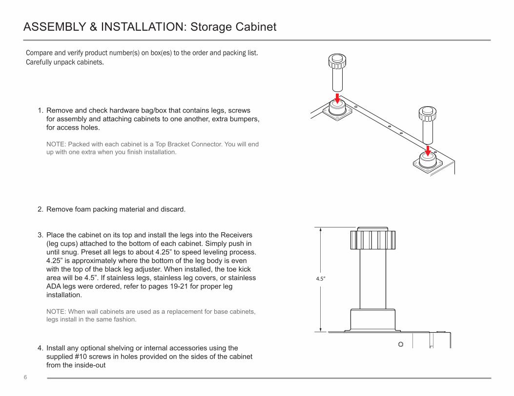
Compare and verify product number(s) on box(es) to the order and packing list. Carefully unpack cabinets.
1. Remove and check hardware bag/box that contains legs, screws for assembly and attaching cabinets to one another, extra bumpers, for access holes.
NOTE: Packed with each cabinet is a Top Bracket Connector. You will end up with one extra when you finish installation.
2. Remove foam packing material and discard.
4.5”
3. Place the cabinet on its top and install the legs into the Receivers (leg cups) attached to the bottom of each cabinet. Simply push in until snug. Preset all legs to about 4.25” to speed leveling process. 4.25” is approximately where the bottom of the leg body is even with the top of the black leg adjuster. When installed, the toe kick area will be 4.5”. If stainless legs, stainless leg covers, or stainless ADA legs were ordered, refer to pages 19-21 for proper leg installation.
NOTE: When wall cabinets are used as a replacement for base cabinets, legs install in the same fashion.
4. Install any optional shelving or internal accessories using the supplied #10 screws in holes provided on the sides of the cabinet from the inside-out
ASSEMBLY & INSTALLATION: Storage Cabinet

7
INSTALLATION: Modification of Standard Legs
In the event that the cabinet needs to sit below our standard minimum leg height, the standard legs can be modified. This modification will allow the legs to be at a reduced height, but still afford the ability for adjustment, ensuring correct leveling of cabinets.
Save
Discard
Cut Here1. Using a saw, cut the leg where indicated in the illustration. Discard the unused portion.
2. Remove any burrs along the outside of the leg.

8
INSTALLATION: Modification of Standard Legs
1. Install the modified leg into the receiver. Push until snug.
2. Adjust the leg as needed for correct height and leveling.

9
ASSEMBLY & INSTALLATION: Drawer Removal
Removal of cabinet drawers allows for ease of moving, assembly and installation.
Be sure to store drawers away from the work site to prevent damage.
Note: Pull-out trash and shelving parts operate in similar fashion, but the Release Levers are located on the sides.
1. Open the drawer fully.
2. Locate the Drawer Release Levers on the underside of the drawer.
3. Depress both Drawer Release levers at the same time and hold.
4. Pull the drawer all the way out of the cabinet. See page 16 for reinstallation instructions.
Drawer Release Lever

10
Once the cabinet(s) are in place, the Shipping Bracket can then be removed.
1. Remove the Shipping Bracket from the front of appliance cabinet by removing the #10 screws. Relocate to the back of the unit using the original screws. This will become the Rear Countertop Support. Its location is dependent upon the depth (front to back) of the grill/appliance, so it is necessary to know the grill manufacturer’s specified depth. Take the manufacturer’s depth and add .5” to the measurement. Then measure from the front, including the door or trim, and locate the pre-drilled holes at that location in the cabinet side walls. Using the original #10 screws, attach the bracket so it is flush with the top of the cabinet.
NOTE: For grills that do not hang from countertop: Cabinets designed for appliances that sit on the deck of the cabinets (e.g. Viking, Dacor, etc.) are shipped with spacers to shim the grill to the height of most granite countertops. If the counter is more than 1” thick, additional shimming must be used (not supplied). Grill liners/insulation jackets are not required nor accounted for in the cabinet design.
2. Remove drawers and accessories that may hinder assembly and store in a safe place.
3. Place the cabinet on its back and install the legs in the Receivers (leg cups) attached to bottom of each cabinet. Simply push in until snug. Preset all legs to about 4.25” to speed the leveling process. When installed, the toe kick area will be 4.5”. Refer to page 17-20 for proper leg installation for all leg options.
4. Grill/Appliance cabinets come with (2) Front Countertop Supports or “U” brackets. These brackets are used primarily as additional countertop support on the side of the grill.
5. Grill/Appliance cabinets come with two (2) bottom & four (4) rear utility access holes (two bottom rear & two top rear). Gas plumbing is typically run through the utility access holes in the floor of the cabinet and then through the access holes in the SS shelf to the fitting on the grill (either left or right side depending on the manufacturer). The plates on the remaining access holes may be removed for airflow as needed.
Shipping Bracket
“U” Bracket
Side Access Hole
Top Rear Access Holes“U” Bracket
ASSEMBLY & INSTALLATION: Appliance and Grill Cabinet

11
Grill TypesHang on Counter Top
Alfresco Kitchen AidBBQ Galore LynxCal Flame NapoleonCapital ProfireDCS SolaireDynasty Twin EaglesFire Magic Vermont CastingsGE VidaliaJenn Air VintageViking Wolf
Sit on SS ShelfDacor Hasty-Bake (charcoal)TEC
Front Trim
SS Shelf
Stiffeners/Shims: Only required for grills that sit on SS shelf
ASSEMBLY & INSTALLATION: Appliance and Grill Cabinet

12
ASSEMBLY & INSTALLATION: Cabinet Installation/Joining Cabinets
1. Place cabinet(s) in final position. Use the cabinet that would be on the highest ground to set the height first, maintaining the minimum 4.5” toe kick height.
NOTE: Place the grill cabinet on the level surface first since it is the most difficult to move around.
2. Partially install #10 screws in Easy-Alignment holes (2nd from bottom on front and rear flange) on right side of cabinet. Do not tighten.
#10 ScrewQTY. 1
13
ASSEMBLY & INSTALLATION: Cabinet Installation/Joining Cabinets
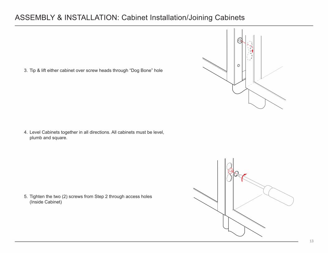
3. Tip & lift either cabinet over screw heads through “Dog Bone” hole
4. Level Cabinets together in all directions. All cabinets must be level, plumb and square.
5. Tighten the two (2) screws from Step 2 through access holes (Inside Cabinet)
14
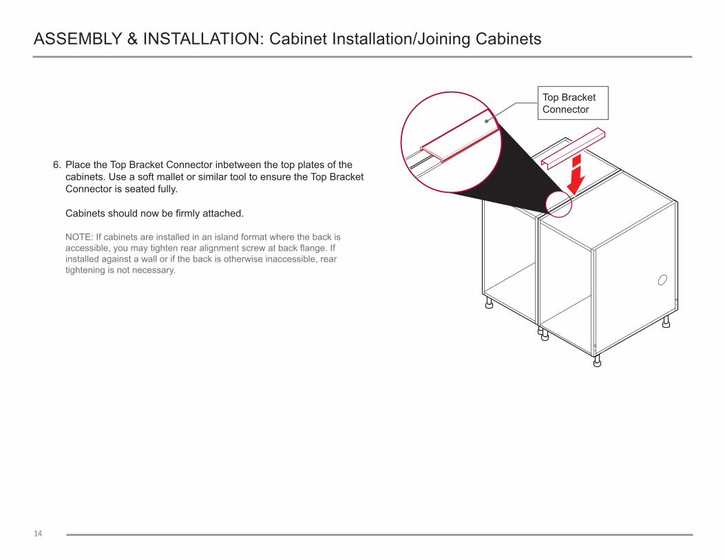
6. Place the Top Bracket Connector inbetween the top plates of the cabinets. Use a soft mallet or similar tool to ensure the Top Bracket Connector is seated fully.
Cabinets should now be firmly attached.
NOTE: If cabinets are installed in an island format where the back is accessible, you may tighten rear alignment screw at back flange. If installed against a wall or if the back is otherwise inaccessible, rear tightening is not necessary.
ASSEMBLY & INSTALLATION: Cabinet Installation/Joining Cabinets
Top Bracket Connector
15
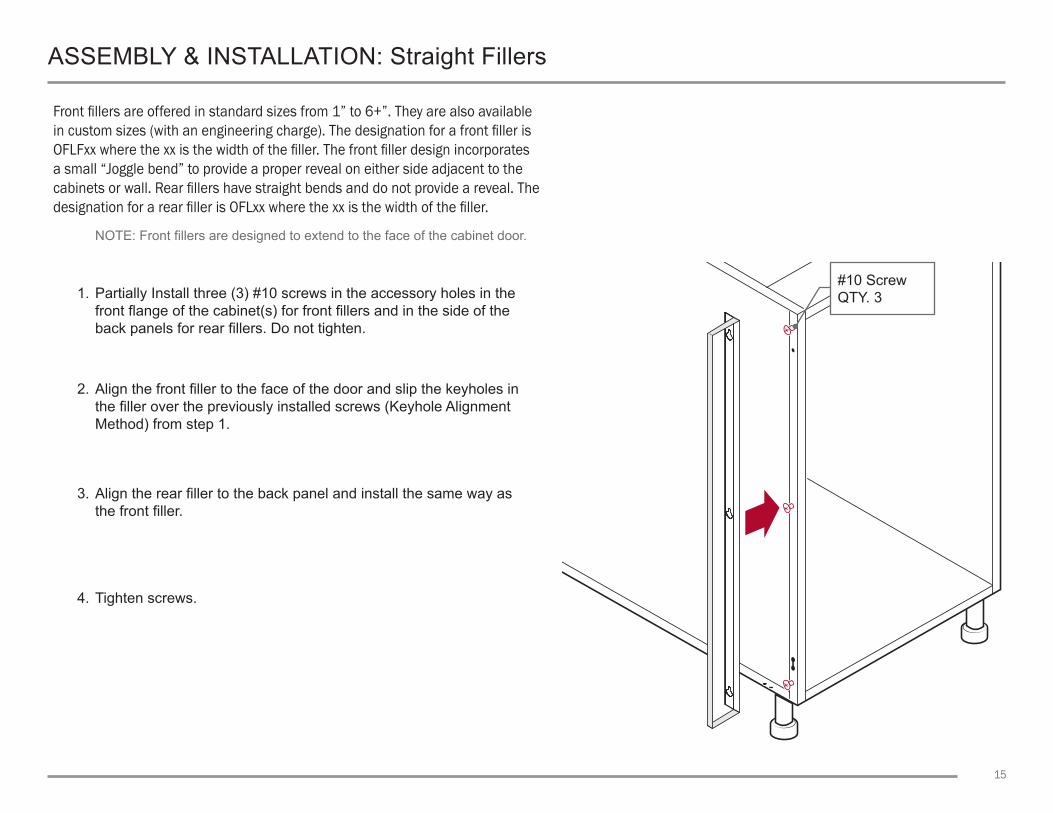
Front fillers are offered in standard sizes from 1” to 6+”. They are also available in custom sizes (with an engineering charge). The designation for a front filler is OFLFxx where the xx is the width of the filler. The front filler design incorporates a small “Joggle bend” to provide a proper reveal on either side adjacent to the cabinets or wall. Rear fillers have straight bends and do not provide a reveal. The designation for a rear filler is OFLxx where the xx is the width of the filler.
NOTE: Front fillers are designed to extend to the face of the cabinet door.
1. Partially Install three (3) #10 screws in the accessory holes in the front flange of the cabinet(s) for front fillers and in the side of the back panels for rear fillers. Do not tighten.
2. Align the front filler to the face of the door and slip the keyholes in the filler over the previously installed screws (Keyhole Alignment Method) from step 1.
3. Align the rear filler to the back panel and install the same way as the front filler.
4. Tighten screws.
ASSEMBLY & INSTALLATION: Straight Fillers
#10 ScrewQTY. 3

16
Angle fillers are offered standard in 90 degree (OAF90 for front, OAR90 for rear) and 45 degree (OAF45, OAR45) with 4” on either side of the angle. Custom sizes are available (with an engineering upcharge). The front angle fillers are installed the same as straight fillers using the Keyhole Alignment Method. The rear angle fillers (OARxx) include an angled post with adjustable leg and two (2) panels to fill a corner void where counter top support is required. For rear angle fillers:
1. Partially Install three (3) #10 screws in the holes on each side of the angled post. Do not tighten.
2. Install three (3) #10 screws in the accessory holes on the rear flange of the cabinet(s) or, if using back panels, in the 3 holes in the side of the back panels installed on the adjacent cabinets. Do not tighten.
3. Install the panels using the Keyhole Alignment Method described earlier.
4. Tighten all screws.
ASSEMBLY & INSTALLATION: Angle Fillers
#10 ScrewQTY. 3

17
ASSEMBLY & INSTALLATION: Angle Fillers
OAR90 or OAR45 rear support column with back panels.
1. Partially Install three (3) #10 screws in the holes on each side of the rear support column. Do not tighten.
2. Install the panels using the Keyhole Alignment Method described earlier.
3. Level together in all directions to ensure parts are level, plumb and square. Tighten all screws.
#10 ScrewQTY. 3 per side
18
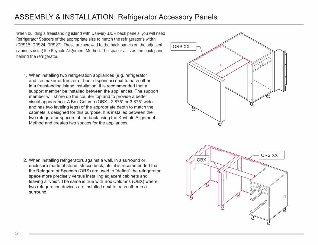
When building a freestanding island with Danver/BJOK back panels, you will need Refrigerator Spacers of the appropriate size to match the refrigerator’s width (ORS15, ORS24, ORS27). These are screwed to the back panels on the adjacent cabinets using the Keyhole Alignment Method. The spacer acts as the back panel behind the refrigerator.
1. When installing two refrigeration appliances (e.g. refrigerator and ice maker or freezer or beer dispenser) next to each other in a freestanding island installation, it is recommended that a support member be installed between the appliances. The support member will shore up the counter top and to provide a better visual appearance. A Box Column (OBX - 2.875” or 3.875” wide and has two leveling legs) of the appropriate depth to match the cabinets is designed for this purpose. It is installed between the two refrigerator spacers at the back using the Keyhole Alignment Method and creates two spaces for the appliances.
2. When installing refrigerators against a wall, in a surround or enclosure made of stone, stucco brick, etc. it is recommended that the Refrigerator Spacers (ORS) are used to “define” the refrigerator space more precisely versus installing adjacent cabinets and leaving a “void”. The same is true with Box Columns (OBX) where two refrigeration devices are installed next to each other in a surround.
ASSEMBLY & INSTALLATION: Refrigerator Accessory Panels
ORS XX
ORS XXOBX

19
ASSEMBLY & INSTALLATION: Refrigerator Accessory Panels
3. In addition to the refrigerator spacer, when installing a refrigerator at the end of a cabinet run with a stainless side panel and/or back panel(s), you will need a Refrigerator End Panel (ORP - 2.875” or 3.875” wide with two leveling legs) of the appropriate depth.
NOTE: The difference between the ORP and the OBX is that the ORP is completely finished on one side with access holes on the other side while the OBX is finished on the front and back with access holes on both sides. The Keyhole Alignment Method is used to screw the ORP to the refrigerator spacer (ORS) and the spacer to the adjacent cabinet.
4. If the refrigerator is to be installed on one side of a corner, and an OAF (front angle filler) should be used with an OBX support column. In this instance, the OAF will mount in front of the OBX by aligning the screw holes at the front of the OBX with the holes in the OAF but at the back of the OAF.
OAF90Front Only
OBX

20
A black 3mm anodized aluminum toe kick with a plastic interior is sold in 7’ (84”) lengths at 4.375” high.
1. Cut toe kick to the appropriate length for your cabinet run using a saw with blade suitable for cutting anodized aluminum. Lay the toe kick in position in front of the cabinet(s).
#8 x .50”
4.5”
.50”2. Drill a 1/8” pilot hole approximately 1/2’ below the top of the toe kick.
3. Screw the #8 screw (included) into the receiver of the leg.
4. Repeat for all toe kicks.
ASSEMBLY & INSTALLATION: Toe Kick
21
ASSEMBLY & INSTALLATION: Stainless Steel Leg Covers
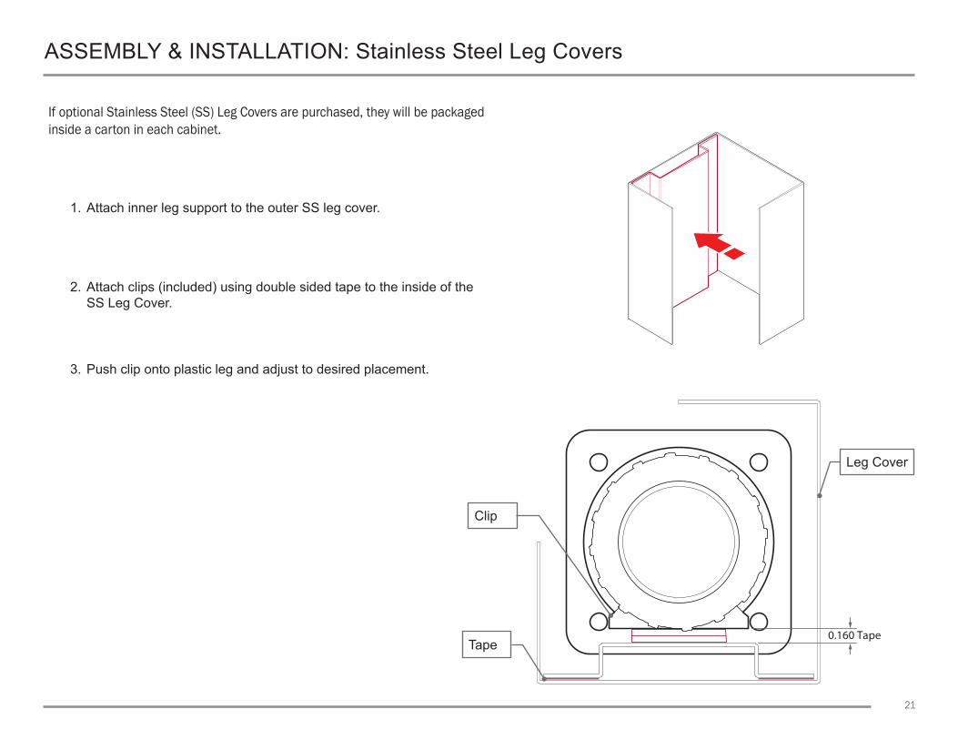
If optional Stainless Steel (SS) Leg Covers are purchased, they will be packaged inside a carton in each cabinet.
1. Attach inner leg support to the outer SS leg cover.
2. Attach clips (included) using double sided tape to the inside of the SS Leg Cover.
3. Push clip onto plastic leg and adjust to desired placement.
0.160 TapeTape
Leg Cover
Clip

22
ASSEMBLY & INSTALLATION: Stainless Steel Leg/ADA Leg Assembly
SS Legs and ADA SS Leg are packed in boxes inside the designated cabinet.
1. Cabinets include foot brackets attached to the bottom with #10 screws.
2. Remove the #10 screws, while leaving the foot bracket in place.
3. Place the SS leg on top of the foot bracket while lining the holes up and reinstall the #10 screws.
#10 ScrewQTY. 3

23
ASSEMBLY & INSTALLATION: ADA Leg Square
ADA Square Legs come attached to foot brackets and are packed in boxes inside the designated cabinet. #10 Screws are included for installation.
1. Place the ADA Square Leg assembly on each corner on the bottom of the cabinet.
2. Attach to the corner with the included #10 screws.
#10 ScrewQTY. 3

24
ASSEMBLY & INSTALLATION: Cabinet Door Adjustment
Adjust cabinet doors after all appliances, counter top and other finish work is complete.
1. The front screw is used to center the door in the opening.
2. The rear screw is used to align the front of the door with the cabinet frame and to secure the door to the cabinet. Slightly loosen screw (while holding the door) and slide the door in and out until aligned. Re-tighten.
3. Loosen the hinge plate mounting screws and slide hinges up or down for further adjust, if necessary. Once aligned, re-tighten.
Front Screw
Rear Screw
Hinge Plate Mounting Screws
25
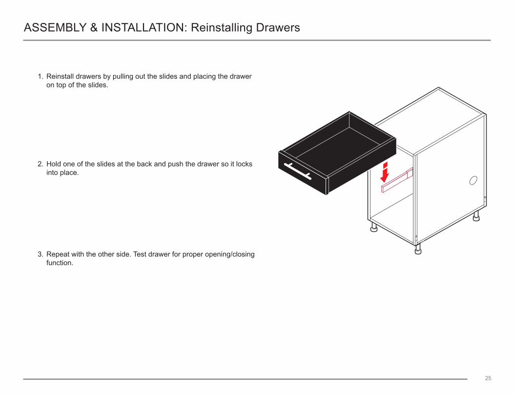
ASSEMBLY & INSTALLATION: Reinstalling Drawers
1. Reinstall drawers by pulling out the slides and placing the drawer on top of the slides.
2. Hold one of the slides at the back and push the drawer so it locks into place.
3. Repeat with the other side. Test drawer for proper opening/closing function.

26
ASSEMBLY & INSTALLATION: Drawer Adjustment
Once cabinets are properly leveled and installed, no drawer adjustment should be required. In the event the drawer does need adjustment, locate the proper adjustment lever(s) on the underside of the drawer.
1. Open the drawer fully.
2. Thumbwheel: adjusts the drawer’s position from left to right.
3. Slider: adjusts the drawer’s position up and down.
4. Close drawer and check adjustment. Repeat as needed.
Thumbwheel: left/right adjustment
Slider: up/down adjustment

27
ASSEMBLY & INSTALLATION: PPS System
The Post and Panel System (PPS) ships flat, requiring assembly.
1. Working from either a standard grill/appliance base cabinet or end panel, attach (4) #10 Screws to the base cabinet. Do not tighten.
2. Attach the Front and Rear Spacer Panels. Tighten the Screws.
Outer Panel(s)
Top Spacer Panels
Front and Rear Spacer Panels
Electrical Cutout(Optional)
Base Cabinet/PPS Support Column

28
ASSEMBLY & INSTALLATION: PPS Outer Panels
The Outer Panels* for the PPS base cabinetry are held in place by ¼” tabs on the top and bottom.
*Note: Outer Panels are required, but ordered separately to accommodate possible width differences between the Front/Rear Spacer Panels.
1. Bend the (4) tabs of the Outer Panels.
2. Attach the Top Panel Mounting Brackets (when required) using (2) #10 Screws. Tighten the Screws.
3. Attach the Top Spacer Panel to the Top Panel Mounting Brackets using (2) #10 Screws. Tighten the Screws.
4. OPTIONAL: In high wind areas, use the (2) additional tabs, located on the top of the Front and Rear Spacer Panels to secure the Outer Panels.
1/4” Tab
1/4” Tab
Outer Panel(s)
Front and Rear Spacer Panels
29
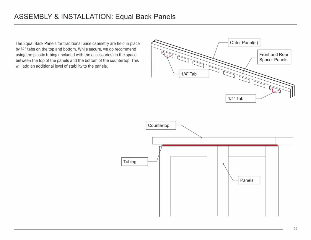
ASSEMBLY & INSTALLATION: Equal Back Panels
The Equal Back Panels for traditional base cabinetry are held in place by ¼” tabs on the top and bottom. While secure, we do recommend using the plastic tubing (included with the accessories) in the space between the top of the panels and the bottom of the countertop. This will add an additional level of stability to the panels.
Tubing
1/4” Tab
Panels
1/4” Tab
Countertop
Outer Panel(s)
Front and Rear Spacer Panels

30
ASSEMBLY & INSTALLATION: Side and Back Panels
The Side (OSP) and Back (OBP) panels install in the same fashion.
1. Place the panel on the cabinet’s bottom lip. The screws on the panel’s bottom are for alignment only and will sit in the large holes located in the lip.
2. After the panel is inserted into the cabinet’s bottom lip, swing the panel into place.
3. Install the two (2) #10 screws from inside the cabinet into the panel and tighen to secure.
Note: The panel will sit under the top lip of the cabinet and can easily be removed, if necessary.
Panel
Cabinet Bottom Lip

31
1. Determine placement of the columns behind the cabinets.
2. Use the adjustable feet to maintain correct height.
3. With the OCP column held in position, drill (4) .156” diameter holes in a staggered pattern from inside, through the cabinet or panel into the OCP column.
NOTE: Staggered hole location is not ciritcal and dependent on your cabinet and setup.
4. Remove the OCP column.
5. Enlarge the (4) holes in the cabinet or panel to .200”.
6. Reattach the OCP column to the cabinet using the supplied 2.50” long screws. Shorter screws should be used when installing on panels, such as an ORS or OAR.
7. The OCP Spans should be cut so they are centered on the columns. Remove the Top Bracket, Install the OCP Spans. Reinstall the Top Bracket.
INSTALLATION: OCP Column
.156” dia. screw holes
QTY. 4
Optional Electrical Cutout
Top Bracket - Fits over column to allow for a large gluing surface
Adjustable Feet
OCP 1x 1 Span - Apply glue on top of tubing for countertop adhesion
Sliding Bracket Covers Feet

Revision: 01_21
1 Grand Street, Wallingford, CT 06492203-269-2300 • Danver.com
18” 48” 12” 30” 24 1/4” 36”