Installation Guide Silicone Coolant · PDF fileInstallation Guide . Silicone Cooling System...
12
SAAB 99 Series 1981 – 1984 H Type Engine Installation Guide Silicone Cooling System Hoses Classic Silicone Hoses http://www.classicsiliconehoses.com/ Disclaimer – This document is for reference purposes only. If you have any doubts about your abilities to carry out the steps outlined in this document please engage the services of a competent service facility. SAAB 99 H Engine Silicone Hose Installation Rev01.doc 1
Transcript of Installation Guide Silicone Coolant · PDF fileInstallation Guide . Silicone Cooling System...
SAAB 99 Series 1981 – 1984
H Type Engine
Installation Guide Silicone Cooling System Hoses
Classic Silicone Hoses http://www.classicsiliconehoses.com/
Disclaimer – This document is for reference purposes only. If you have any doubts about your abilities to carry out the steps outlined in this document please engage the services of a competent service facility.
SAAB 99 H Engine Silicone Hose Installation Rev01.doc 1

Terminology: Drivers Side – refers to the Drivers side of Left Hand Drive cars. Offside – refers to the Drivers side of Right Hand Drive cars. Passenger Side – refers to the Passenger side of Left Hand Drive cars. Nearside – refers to the Passenger side of Right Hand Drive cars. In this document the standard reference for both types of vehicles will be left hand drive first, a slash and then right hand drive. For example, the radiator drain plug can be found at the bottom of the radiator on the 'Drivers Side / Offside'. Tools Required;
1. Philips head screwdrivers (1 long handle, 1 stubby) 2. Slot head screwdriver (for hose clamps) OR (see #3 for better solution) 3. 7 mm 1/4” drive socket (with ratchet or 'screwdriver' handle) 4. 11 mm open end or box end wrench / spanner (cooling system air bleed
screws) 5. 19 mm socket 3/8” drive socket (optional – for draining engine block) 6. 22 mm open end wrench / spanner for the radiator drain fitting 7. Putty knife or similar scrapper 8. Non hardening gasket maker or similar sealer 9. Anti-freeze solution 10. Drain pan for coolant 11. 40 – 60cm length of 1/2” garden hose (for radiator drain fitting) 12. Funnel and pieces of cheese cloth or similar 'filtering' material 13. Emery cloth 180 grit (a couple to strips 2cm wide and 25cm long) 14. 1 metre length of 6 mm vacuum hose (bleeding air from system) 15. Sharp knife (Stanley or equivalent) 16. Carpet knife (optional – for releasing old hoses) 17. Scotch Brite pad (medium grade) 18. 30cm length of foam weather stripping ~6 mm wide and ~4 mm thick
SAAB 99 H Engine Silicone Hose Installation Rev01.doc 2

1. Connect a 40 – 60cm length of ½” garden hose to the radiator drain plug. Slide the drain pan under the engine and make sure the hose reaches the pan. Antifreeze solutions are harmful to animals so be careful.
2. Set the heater temperature control to maximum to open the valve to the matrix. Using the 22 mm open end wrench / spanner open the drain plug and let ~ 2 litres of coolant drain from the system. Unfortunately this won't drain the coolant from the water pump and some of the connecting hoses. If you wish to drain these, the only way is to disconnect the hose between the radiator expansion tank and the water pump and carefully pour out the contents or use a siphon hose.
SAAB 99 H Engine Silicone Hose Installation Rev01.doc 3

3. If you plan to drain the complete cooling system. Use the 19 mm socket on the drain bolt located on the lower block, under the exhaust manifold, just above the engine mount bracket. NOTE – the drain bolt has a small thin (18 mm diameter, 2 mm wide and 1 mm thick), flat washer that is VERY easily lost. Keep an eye on it during removal and reinstallation. CAUTION – be careful using the ratchet and socket in this area, the battery connection to the starter is in the area. If in doubt, disconnect both battery cables (make sure you have your stereo security code if this is required to use the system afterwards).
4. Remove the thermostat housing to radiator hose. If the hose is an old one it may be best to cut it. A carpet knife (hooked blade), is great for this as it won't score the metal surface. The alloy casting for the thermostat housing will more than likely have some calcium or other deposits on the surface. These MUST be removed to ensure a water tight fit for the new hose. Wrap a piece of Emery cloth around the casting and holding each end with your thumb and fore finger pull it back and forth. When you think the complete circumference of the fitting is clean do it one more time. The surface should be as smooth as the proverbial babies’ bottom. Check the radiator fitting, it will probably be OK but a quick clean up with a Scotch Brite pad won't hurt.
Distributor cap and rotor removed for clarity
SAAB 99 H Engine Silicone Hose Installation Rev01.doc 4

5. Next remove the three hoses connecting the water pump to the expansion tank, intake manifold and heater matrix. All the hose fittings on the water pump and intake manifold are alloy. Like the thermostat housing, this will have some build up of deposits – these must be cleaned off (see point 4 on the previous page).
Before After 6. If you are planning to replace the heater matrix hoses, the housing will need to be opened up. There are 3 Philips head screws on each end (white arrows). It is recommended that the air bleed screw and the control valve cover screw are also removed (red arrows). With the air bleed screw removed the control valve cover can be easily removed.
SAAB 99 H Engine Silicone Hose Installation Rev01.doc 5

SAAB 99 H Engine Silicone Hose Installation Rev01.doc 6
e
t ive cars can only be accessed by reaching around behind the brake
ervo.
s. y
f the open grille design of the air
intake below the windshield / wind screen.
7. To remove and replace the hose between the heater matrix and the controlvalve will need to be separated from the mounting bracket. It is held in placwith three Philips head screws. These can only be removed with a stubby Philips head screwdriver. The one at the back is especially difficult and on lefhand drs
8. The heater matrix has a metal cover held on by three Philips head screwRemove these to check the condition of the matrix as well as the capillartube for temperature regulation of the control valve. If the heater matrix housing has never been opened the underside of the matrix itself will be quiteclogged with leaves and debris as a result o
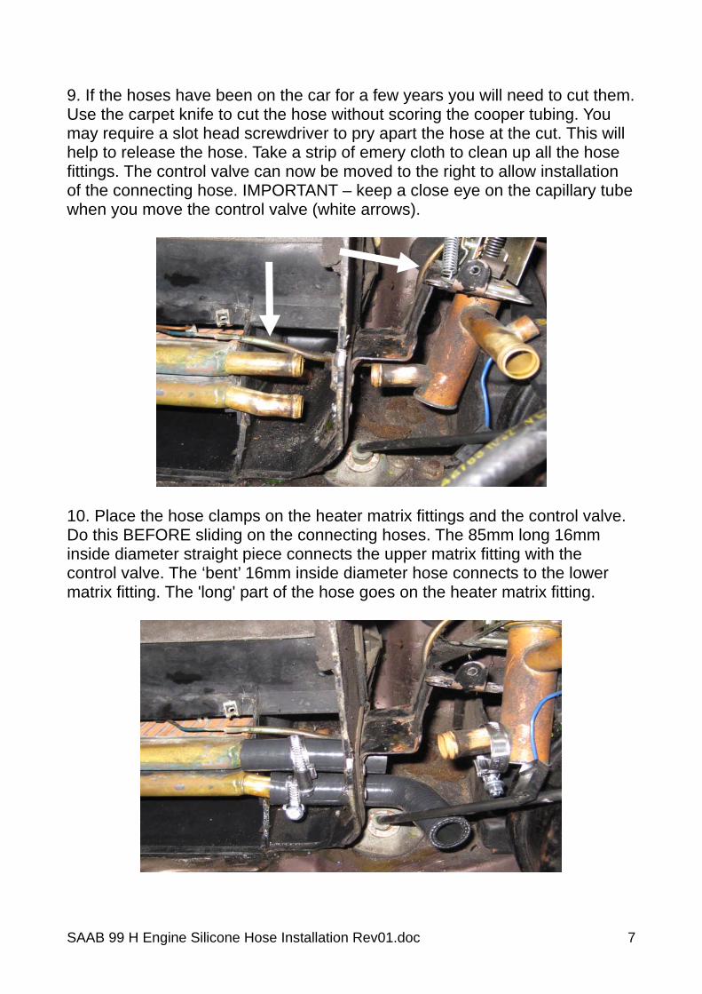
9. If the hoses have been on the car for a few years you will need to cut them. Use the carpet knife to cut the hose without scoring the cooper tubing. You may require a slot head screwdriver to pry apart the hose at the cut. This will help to release the hose. Take a strip of emery cloth to clean up all the hose fittings. The control valve can now be moved to the right to allow installation of the connecting hose. IMPORTANT – keep a close eye on the capillary tube when you move the control valve (white arrows).
10. Place the hose clamps on the heater matrix fittings and the control valve. Do this BEFORE sliding on the connecting hoses. The 85mm long 16mm inside diameter straight piece connects the upper matrix fitting with the control valve. The ‘bent’ 16mm inside diameter hose connects to the lower matrix fitting. The 'long' part of the hose goes on the heater matrix fitting.
SAAB 99 H Engine Silicone Hose Installation Rev01.doc 7
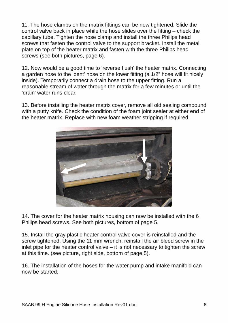
11. The hose clamps on the matrix fittings can be now tightened. Slide the control valve back in place while the hose slides over the fitting – check the capillary tube. Tighten the hose clamp and install the three Philips head screws that fasten the control valve to the support bracket. Install the metal plate on top of the heater matrix and fasten with the three Philips head screws (see both pictures, page 6). 12. Now would be a good time to 'reverse flush' the heater matrix. Connecting a garden hose to the 'bent' hose on the lower fitting (a 1/2” hose will fit nicely inside). Temporarily connect a drain hose to the upper fitting. Run a reasonable stream of water through the matrix for a few minutes or until the 'drain' water runs clear. 13. Before installing the heater matrix cover, remove all old sealing compound with a putty knife. Check the condition of the foam joint sealer at either end of the heater matrix. Replace with new foam weather stripping if required.
14. The cover for the heater matrix housing can now be installed with the 6 Philips head screws. See both pictures, bottom of page 5. 15. Install the gray plastic heater control valve cover is reinstalled and the screw tightened. Using the 11 mm wrench, reinstall the air bleed screw in the inlet pipe for the heater control valve – it is not necessary to tighten the screw at this time. (see picture, right side, bottom of page 5). 16. The installation of the hoses for the water pump and intake manifold can now be started.
SAAB 99 H Engine Silicone Hose Installation Rev01.doc 8
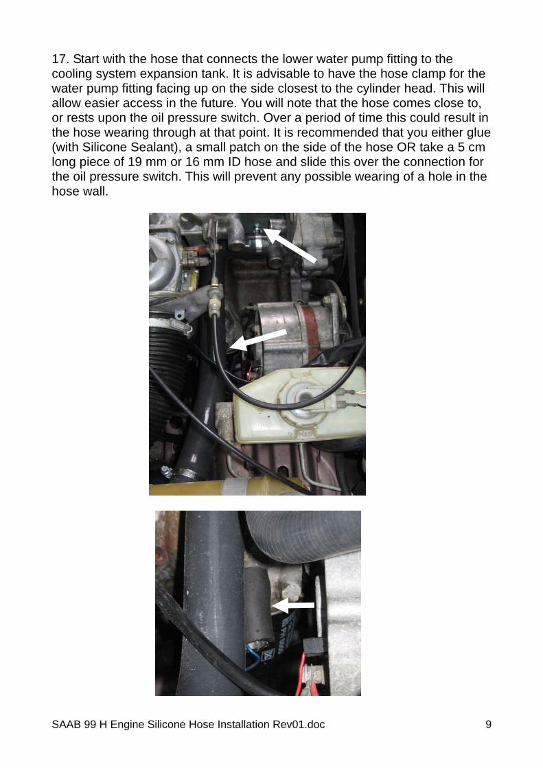
17. Start with the hose that connects the lower water pump fitting to the cooling system expansion tank. It is advisable to have the hose clamp for the water pump fitting facing up on the side closest to the cylinder head. This will allow easier access in the future. You will note that the hose comes close to, or rests upon the oil pressure switch. Over a period of time this could result in the hose wearing through at that point. It is recommended that you either glue (with Silicone Sealant), a small patch on the side of the hose OR take a 5 cm long piece of 19 mm or 16 mm ID hose and slide this over the connection for the oil pressure switch. This will prevent any possible wearing of a hole in the hose wall.
SAAB 99 H Engine Silicone Hose Installation Rev01.doc 9

18. Next the heater matrix return to water pump hose connection can be made. As well as the complex hose that connects the water pump to the intake manifold and the reducer fitting. This fitting takes the 19 mm inside diameter hose outlet to 16 mm inside diameter (see arrow). The 16 mm outlet uses the 100 mm long straight hose for the connection to the heater matrix control valve. NOTE – in the picture on the right, the original SAAB metal reducer has been replaced by a plastic unit manufactured by Gates.
19. Double check all hose connections and the clamps. Clamps should be tight but not overly so. You should see compression of the hose so that the clamp surface is slightly below that of the hose on either side. 20. You can now begin adding the coolant solution – this must be a mix of antifreeze and water (tap water is OK, distilled is better). Refer to the chart on the next page for recommended mixture ratios. Bear in mind that an antifreeze solution, in addition to preventing corrosion of the Aluminium cylinder head also raises the boiling point of the coolant (in combination with a properly functioning coolant system pressure cap).
SAAB 99 H Engine Silicone Hose Installation Rev01.doc 10

DO NOT USE;
1. 100% water in your cooling system, this will result in corrosion. 2. Less than 40% or more then 60% ratio of antifreeze to water in your
cooling system is not recommended. In both cases your protection in cold and hot weather will be reduced.
Coolant Solution
Ratio Antifreeze
to Water Freezing Point Boiling Point Boiling Point
w/15psi Pressure Cap
40% -24ºC 106ºC 127ºC 50% -37ºC 108ºC 130ºC
21. Once you have filled the cooling system it is almost time to start the vehicle and begin the process of purging air. Due to the design of the cooling system, air is easily trapped. SAAB has built two air bleed screws into the system. One in the thermostat housing, the second in the pipe leading to the heater matrix control valve. Set the heater temperature control to maximum. Next attach a piece of 6 mm hose, 80 – 100cm long to the air bleed screw on the thermostat housing. Take the other end of this hose and place it in the cooling system expansion tank. Open the valve ½ to 1 turn using the 11 mm open end wrench / spanner. Ideally this hose should be a clear one such as used for your windshield / screen washer system however a standard piece of vacuum hose will suffice.
(21. cont.)
SAAB 99 H Engine Silicone Hose Installation Rev01.doc 11
SAAB 99 H Engine Silicone Hose Installation Rev01.doc 12
Ensure the hand brake is set, the gearbox is in neutral and start the car. You will immediately begin seeing a steady stream of water and air bubbles moving through the 6 mm hose as the system begins to purge itself. If you are not using clear hose you will see the hose move back and forth every time air bubbles move through it. Purging the system of air takes time and needs to continue after the thermostat has opened and the vehicle reaches operating temperature. So be prepared to spend 10 – 15 minutes for this whole process. Don’t forget to do the same with the air bleed for the heater matrix. This one tends to have very little air and is quickly purged. 22. Check all the hose connections for leaks. Shut the engine down and remove the 6 mm purge hose if still installed. Let the engine cool down for 45 minutes to 1 hour and check the coolant level, add as required. 23. Now, take the car for a 20 – 30 kilometre drive to fully warm up the vehicle. Upon arriving back home, check all hose connections one more time for leakage. By the next day, the coolant system will have stabilised, check the level one more time, add as required. 24. Now sit back and enjoy the fruits of your labour and know that your cooling system hoses will probably outlive your vehicle. Thank you for choosing Classic Silicone Hoses.
http://www.classicsiliconehoses.com/