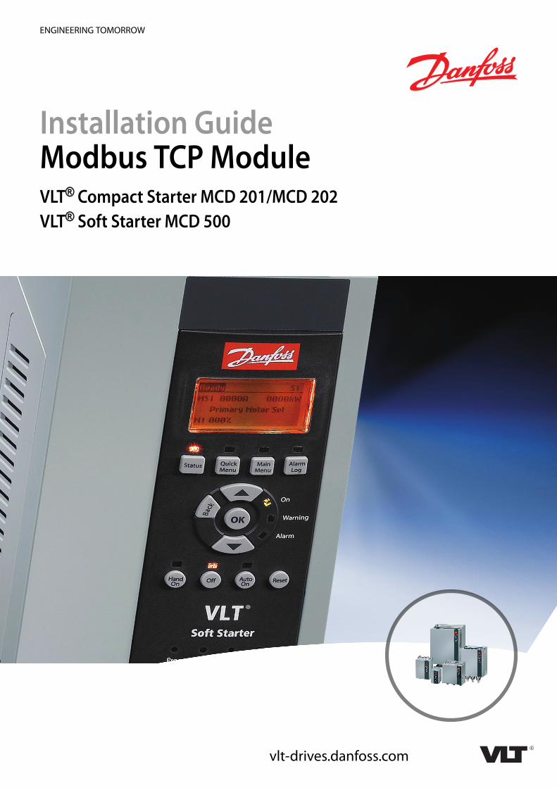
Installation Guide Modbus TCP Module VLT Soft Starter MCD...
24
ENGINEERING TOMORROW Installation Guide Modbus TCP Module VLT ® Compact Starter MCD 201/MCD 202 VLT ® Soft Starter MCD 500 vlt-drives.danfoss.com
Transcript of Installation Guide Modbus TCP Module VLT Soft Starter MCD...
ENGINEERING TOMORROW
Installation GuideModbus TCP ModuleVLT® Compact Starter MCD 201/MCD 202VLT® Soft Starter MCD 500
vlt-drives.danfoss.com


Contents
1 Introduction 3
1.1 Purpose of the Manual 3
1.2 Additional Resources 3
1.3 Product Overview 3
1.4 Approvals and Certifications 3
1.5 Disposal 3
1.6 Symbols, Abbreviations, and Conventions 3
2 Safety 4
2.1 Qualified Personnel 4
2.2 General Warnings 4
3 Installation 6
3.1 Installation Procedure 6
4 Connection 7
4.1 Soft Starter Connection 7
4.2 Network Connection 8
4.2.1 Ethernet Ports 8
4.2.2 Cables 8
4.2.3 EMC Precautions 8
4.2.4 Network Establishment 8
4.3 Addressing 8
5 Device Configuration 9
5.1 Configuration Overview 9
5.2 On-board Web Server 9
5.3 Ethernet Device Configuration Tool 9
6 Operation 11
6.1 Device Classification 11
6.2 Configuration 11
6.3 LEDs 11
7 Modbus Registers 12
7.1 Compatibility 12
7.2 Ensuring Safe and Successful Control 12
7.3 Configuring Soft Starter Parameters 12
7.4 Standard Mode 12
7.4.1 PLC Configuration 12
7.4.2 Command and Configuration Registers (Read/Write) 13
Contents Installation Guide
MG17N102 Danfoss A/S © 10/2017 All rights reserved. 1
7.4.3 Status Reporting Registers (Read Only) 13
7.4.4 Examples 14
7.5 Legacy Mode 15
7.5.1 PLC Configuration 15
7.5.2 Registers 15
7.5.3 Examples 16
7.6 Trip Codes 17
7.6.1 Internal Fault X 17
8 Network Design 18
8.1 Star Topology 18
8.2 Line Topology 18
8.3 Ring Topology 18
8.4 Combined Topologies 19
9 Specifications 20
Index 21
Contents Modbus TCP Module
2 Danfoss A/S © 10/2017 All rights reserved. MG17N102
1 Introduction
1.1 Purpose of the Manual
This installation guide provides information for the instal-lation of the Modbus TCP module for VLT® Compact StarterMCD 201/MCD 202 and VLT® Soft Starter MCD 500.The installation guide is intended for use by qualifiedpersonnel.
Users are assumed to be familiar with:• VLT® soft starters.
• Ethernet protocols.
• PC or PLC that is used as a master in the system.
Read the instructions before installation and ensure thatthe instructions for safe installation are observed.
VLT® is a registered trademark.
1.2 Additional Resources
Resources available for the soft starter and optionalequipment:
• The VLT® Compact Starter MCD 200 OperatingInstructions provide the necessary information forgetting the soft starter up and running.
• The VLT® Soft Starter MCD 500 Operating Guideprovides the necessary information for gettingthe soft starter up and running.
Supplementary publications and manuals are availablefrom Danfoss. See drives.danfoss.com/knowledge-center/technical-documentation/ for listings.
1.3 Product Overview
1.3.1 Intended Use
This installation guide relates to Modbus TCP Module forVLT® soft starters, ordering number 175G9904.
The Modbus TCP Module is intended for use with:• VLT® Compact Starter MCD 201/MCD 202,
24 V AC/V DC and 110/240 V AC control voltage.
• VLT® Soft Starter MCD 500, all models.
NOTICEThe Modbus TCP Module is NOT suitable for use with theMCD 201/MCD 202 compact starters using 380/440 V ACcontrol voltage.
The Modbus TCP Module allows a Danfoss soft starter toconnect to an Ethernet network and be controlled ormonitored using an Ethernet communication model.
Familiarity with Ethernet protocols and networks isrequired to operate the device successfully. If there aredifficulties when using this device with third-partyproducts, including PLCs, scanners, and commissioningtools, contact the relevant supplier.
1.4 Approvals and Certifications
More approvals and certifications are available. For moreinformation, contact a local Danfoss partner.
1.5 Disposal
Do not dispose of equipment containingelectrical components together withdomestic waste.Collect it separately in accordance withlocal and currently valid legislation.
1.6 Symbols, Abbreviations, andConventions
Abbreviation Definition
DHCP Dynamic host configuration protocol
EMC Electromagnetic compatibility
IP Internet protocol
LCP Local control panel
LED Light-emitting diode
LOP Local operation panel
PC Personal computer
PLC Programmable logic controller
Table 1.1 Symbols and Abbreviations
ConventionsNumbered lists indicate procedures.Bullet lists indicate other information and description ofillustrations.
Italicized text indicates:• Cross-reference.
• Link.
• Parameter name.
• Parameter group name.
• Parameter option.
Introduction Installation Guide
MG17N102 Danfoss A/S © 10/2017 All rights reserved. 3
1 1
2 Safety
The following symbols are used in this manual:
WARNINGIndicates a potentially hazardous situation that couldresult in death or serious injury.
CAUTIONIndicates a potentially hazardous situation that couldresult in minor or moderate injury. It can also be used toalert against unsafe practices.
NOTICEIndicates important information, including situations thatcan result in damage to equipment or property.
2.1 Qualified Personnel
Correct and reliable transport, storage, installation,operation, and maintenance are required for the trouble-free and safe operation of the soft starter. Only qualifiedpersonnel are allowed to install or operate this equipment.
Qualified personnel are defined as trained staff, who areauthorized to install, commission, and maintain equipment,systems, and circuits in accordance with pertinent laws andregulations. Also, the qualified personnel must be familiarwith the instructions and safety measures described in thisinstallation guide.
2.2 General Warnings
WARNINGELECTRICAL SHOCK HAZARDVLT® Soft Starter MCD 500 contains dangerous voltageswhen connected to mains voltage. Only a qualifiedelectrician should carry out the electrical installation.Improper installation of the motor or the soft starter cancause death, serious injury, or equipment failure. Followthe guidelines in this manual and local electrical safetycodes.Models MCD5-0360C ~ MCD5-1600C:Treat the busbar and heat sink as live parts wheneverthe unit has mains voltage connected (including whenthe soft starter is tripped or waiting for a command).
WARNINGPROPER GROUNDINGDisconnect the soft starter from mains voltage beforecarrying out repair work.It is the responsibility of the person installing the softstarter to provide proper grounding and branch circuitprotection according to local electrical safety codes.Do not connect power factor correction capacitors to theoutput of the VLT® Soft Starter MCD 500. If static powerfactor correction is employed, it must be connected tothe supply side of the soft starter.
WARNINGIMMEDIATE STARTIn auto-on mode, the motor can be controlled remotely(via remote inputs) while the soft starter is connected tomains.MCD5-0021B ~ MCD5-0961B:Transportation, mechanical shock, or rough handlingmay cause the bypass contactor to latch into the Onstate.
To prevent the motor from starting immediately on firstcommissioning or operation after transportation:
• Always ensure that the control supply is appliedbefore the power.
• Applying control supply before power ensuresthat the contactor state is initialized.
WARNINGUNINTENDED STARTWhen the soft starter is connected to AC mains, DCsupply, or load sharing, the motor can start at any time.Unintended start during programming, service, or repairwork can result in death, serious injury, or propertydamage. The motor can start with an external switch, afieldbus command, an input reference signal from theLCP or LOP, via remote operation using MCT 10 Set-upSoftware, or after a cleared fault condition.
To prevent unintended motor start:• Press [Off]/[Reset] on the LCP before
programming parameters.
• Disconnect the soft starter from mains.
• Completely wire and assemble the soft starter,motor, and any driven equipment beforeconnecting the soft starter to AC mains, DCsupply, or load sharing.
Safety Modbus TCP Module
4 Danfoss A/S © 10/2017 All rights reserved. MG17N102
22
WARNINGSAFETY OF PERSONNELThe soft starter is not a safety device and does notprovide electrical isolation or disconnection from thesupply.
• If isolation is required, the soft starter must beinstalled with a main contactor.
• Do not rely on the start and stop functions forsafety of personnel. Faults occurring in themains supply, the motor connection, or theelectronics of the soft starter can causeunintended motor starts or stops.
• If faults occur in the electronics of the softstarter, a stopped motor may start. A temporaryfault in the supply mains or loss of motorconnection can also cause a stopped motor tostart.
To provide safety of personnel and equipment, controlthe isolation device through an external safety system.
NOTICEBefore changing any parameter settings, save the currentparameter to a file using MCD PC Software or the SaveUser Set function.
NOTICEUse the autostart feature with caution. Read all the notesrelated to autostart before operation.
The examples and diagrams in this manual are includedsolely for illustrative purposes. The information containedin this manual is subject to change at any time andwithout prior notice. Responsibility or liability is neveraccepted for direct, indirect, or consequential damageresulting from the use or application of this equipment.
Safety Installation Guide
MG17N102 Danfoss A/S © 10/2017 All rights reserved. 5
2 2

3 Installation
3.1 Installation Procedure
CAUTIONEQUIPMENT DAMAGEIf mains and control voltage are applied when installingor removing options/accessories, it may damage theequipment.
To avoid damage:• Remove mains and control voltage from the
soft starter before attaching or removingoptions/accessories.
Installing the Modbus TCP Module:1. Remove control power and mains supply from
the soft starter.
2. Fully pull out the top and bottom retaining clipson the module (A).
3. Line up the module with the communication portslot (B).
4. Push in the top and bottom retaining clips tosecure the module to the soft starter (C).
5. Connect Ethernet port 1 or port 2 on the ModbusTCP Module to the network.
6. Apply control power to the soft starter.
177H
A52
8.13
A B C
Illustration 3.1 Installing the Modbus TCP Module
Remove the module from the soft starter:1. Remove control power and mains supply from
the soft starter.
2. Disconnect all external wiring from the module.
3. Fully pull out the top and bottom retaining clipson the module (A).
4. Pull the module away from the soft starter.
177H
A37
8.12
A
Illustration 3.2 Removing the Modbus TCP Module
Installation Modbus TCP Module
6 Danfoss A/S © 10/2017 All rights reserved. MG17N102
33
4 Connection
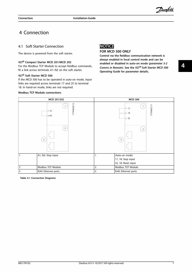
4.1 Soft Starter Connection
The device is powered from the soft starter.
VLT® Compact Starter MCD 201/MCD 202For the Modbus TCP Module to accept fieldbus commands,fit a link across terminals A1–N2 on the soft starter.
VLT® Soft Starter MCD 500If the MCD 500 has to be operated in auto-on mode, inputlinks are required across terminals 17 and 25 to terminal18. In hand-on mode, links are not required.
NOTICEFOR MCD 500 ONLYControl via the fieldbus communication network isalways enabled in local control mode and can beenabled or disabled in auto-on mode (parameter 3-2Comms in Remote). See the VLT® Soft Starter MCD 500Operating Guide for parameter details.
Modbus TCP Module connections
MCD 201/202 MCD 500
N2 177H
A62
0.12
1
2
3
A117
18
25
177H
A62
1.111
2
3
1 A1, N2: Stop input 1 (Auto-on mode)17, 18: Stop input25, 18: Reset input
2 Modbus TCP Module 2 Modbus TCP Module
3 RJ45 Ethernet ports 3 RJ45 Ethernet ports
Table 4.1 Connection Diagrams
Connection Installation Guide
MG17N102 Danfoss A/S © 10/2017 All rights reserved. 7
4 4
4.2 Network Connection
4.2.1 Ethernet Ports
The device has 2 Ethernet ports. If only 1 connection isrequired, either port can be used.
4.2.2 Cables
Suitable cables for EtherNet/IP Module connection:• Category 5
• Category 5e
• Category 6
• Category 6e
4.2.3 EMC Precautions
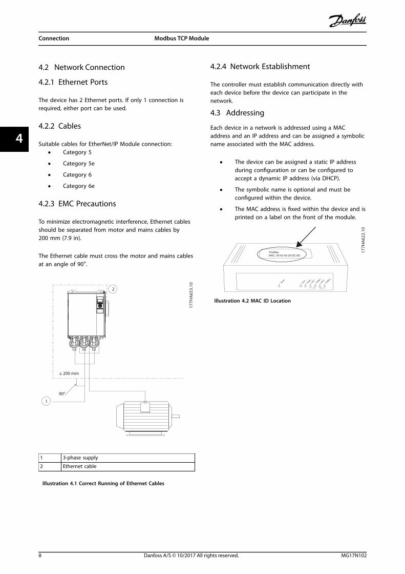
To minimize electromagnetic interference, Ethernet cablesshould be separated from motor and mains cables by200 mm (7.9 in).
The Ethernet cable must cross the motor and mains cablesat an angle of 90°.
1
2
≥ 200 mm
90°
177H
A65
3.10
1 3-phase supply
2 Ethernet cable
Illustration 4.1 Correct Running of Ethernet Cables
4.2.4 Network Establishment
The controller must establish communication directly witheach device before the device can participate in thenetwork.
4.3 Addressing
Each device in a network is addressed using a MACaddress and an IP address and can be assigned a symbolicname associated with the MAC address.
• The device can be assigned a static IP addressduring configuration or can be configured toaccept a dynamic IP address (via DHCP).
• The symbolic name is optional and must beconfigured within the device.
• The MAC address is fixed within the device and isprinted on a label on the front of the module.
ProfiNetMAC: 00-02-A2-25-DC-B3
1 2
TX/RX 2
TX/RX 1
Link 2Link 1
Error
Statu
s
Power
177H
A62
2.10
Illustration 4.2 MAC ID Location
Connection Modbus TCP Module
8 Danfoss A/S © 10/2017 All rights reserved. MG17N102
44
5 Device Configuration
5.1 Configuration Overview
NOTICEThe error LED flashes whenever the device is receivingpower but is not connected to a network. The error LEDflashes throughout the configuration process.
5.2 On-board Web Server
Ethernet attributes can be configured directly in the deviceusing the on-board web server.
NOTICEThe web server only accepts connections from within thesame subnet domain.
To configure the device using the on-board web server:1. Attach the module to a soft starter.
2. Connect Ethernet port 1 or port 2 on the ModbusTCP Module to the network.
3. Apply control power to the soft starter.
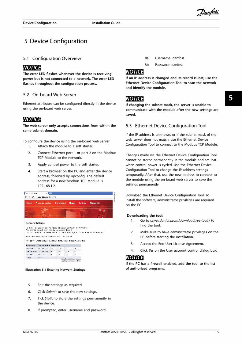
4. Start a browser on the PC and enter the deviceaddress, followed by /ipconfig. The defaultaddress for a new Modbus TCP Module is192.168.1.2.
e77h
a639
.10
Illustration 5.1 Entering Network Settings
5. Edit the settings as required.
6. Click Submit to save the new settings.
7. Tick Static to store the settings permanently inthe device.
8. If prompted, enter username and password.
8a Username: danfoss
8b Password: danfoss
NOTICEIf an IP address is changed and its record is lost, use theEthernet Device Configuration Tool to scan the networkand identify the module.
NOTICEIf changing the subnet mask, the server is unable tocommunicate with the module after the new settings aresaved.
5.3 Ethernet Device Configuration Tool
If the IP address is unknown, or if the subnet mask of theweb server does not match, use the Ethernet DeviceConfiguration Tool to connect to the Modbus TCP Module.
Changes made via the Ethernet Device Configuration Toolcannot be stored permanently in the module and are lostwhen control power is cycled. Use the Ethernet DeviceConfiguration Tool to change the IP address settingstemporarily. After that, use the new address to connect tothe module using the on-board web server to save thesettings permanently.
Download the Ethernet Device Configuration Tool. Toinstall the software, administrator privileges are requiredon the PC.
Downloading the tool:1. Go to drives.danfoss.com/downloads/pc-tools/ to
find the tool.
2. Make sure to have administrator privileges on thePC before starting the installation.
3. Accept the End-User License Agreement.
4. Click Yes on the User account control dialog box.
NOTICEIf the PC has a firewall enabled, add the tool to the listof authorized programs.
Device Configuration Installation Guide
MG17N102 Danfoss A/S © 10/2017 All rights reserved. 9
5 5
Configuring the device using the Ethernet DeviceConfiguration Tool:
1. Attach the module to a soft starter.
2. Connect Ethernet port 1 or port 2 on the moduleto the network.
3. Apply control power to the soft starter.
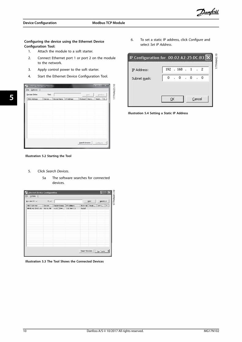
4. Start the Ethernet Device Configuration Tool.
177H
A62
3.10
Illustration 5.2 Starting the Tool
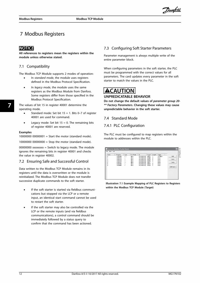
5. Click Search Devices.
5a The software searches for connecteddevices.
177H
A64
1.10
Illustration 5.3 The Tool Shows the Connected Devices
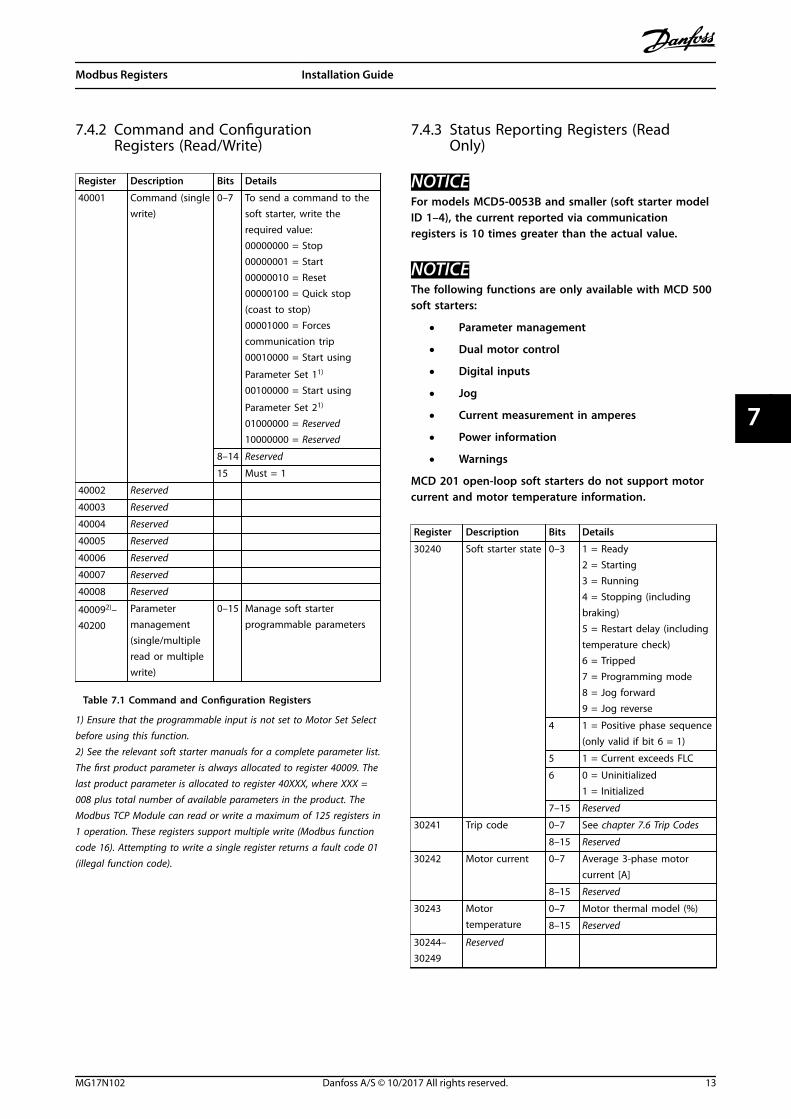
6. To set a static IP address, click Configure andselect Set IP Address.
177H
A64
2.10
Illustration 5.4 Setting a Static IP Address
Device Configuration Modbus TCP Module
10 Danfoss A/S © 10/2017 All rights reserved. MG17N102
55

6 Operation
The Modbus TCP Module must be controlled by a Modbusclient (such as a PLC) which complies with the ModbusProtocol Specification. For successful operation, the clientmust also support all functions and interfaces described inthis manual.
6.1 Device Classification
The Modbus TPC Module is a Modbus server managed bya Modbus client over Ethernet.
6.2 Configuration
Configure the device directly in the PLC. No additional filesare required.
6.3 LEDs
LED name LED status Description
12
TX/RX 2
TX/RX 1Link 2
Link 1
ErrorStatus
Power 177H
A62
7.10 Power
Off The module is not powered up.
On The module receives power.
Error
Off No error.
Flashing System error.
On Communication error.
Status
Off Not ready.
Slow flash Ready, but not configured.
Fast flash Configured and waiting for communication.
On Communication has been established.
Link xOff No network connection.
On Connected to a network.
TX/RX x Flashing Establishing connection.
On Normal operation.
Table 6.1 Feedback LEDs
Operation Installation Guide
MG17N102 Danfoss A/S © 10/2017 All rights reserved. 11
6 6
7 Modbus Registers
NOTICEAll references to registers mean the registers within themodule unless otherwise stated.
7.1 Compatibility
The Modbus TCP Module supports 2 modes of operation:• In standard mode, the module uses registers
defined in the Modbus Protocol Specification.
• In legacy mode, the module uses the sameregisters as the Modbus Module from Danfoss.Some registers differ from those specified in theModbus Protocol Specification.
The values of bit 15 in register 40001 determine theoperating mode.
• Standard mode: Set bit 15 = 1. Bits 0–7 of register40001 are used for command.
• Legacy mode: Set bit 15 = 0. The remaining bitsof register 40001 are reserved.
Examples10000000 00000001 = Start the motor (standard mode).
10000000 00000000 = Stop the motor (standard mode).
00000000 xxxxxxxx = Switch to legacy mode. The moduleignores the remaining bits in register 40001 and checksthe value in register 40002.
7.2 Ensuring Safe and Successful Control
Data written to the Modbus TCP Module remains in itsregisters until the data is overwritten or the module isreinitialized. The Modbus TCP Module does not transfersuccessive duplicate commands to the soft starter.
• If the soft starter is started via fieldbus communi-cations but stopped via the LCP or a remoteinput, an identical start command cannot be usedto restart the soft starter.
• If the soft starter may also be controlled via theLCP or the remote inputs (and via fieldbuscommunications), a control command should beimmediately followed by a status query toconfirm that the command has been actioned.
7.3 Configuring Soft Starter Parameters
Parameter management is always multiple write of theentire parameter block.
When configuring parameters in the soft starter, the PLCmust be programmed with the correct values for allparameters. The card updates every parameter in the softstarter to match the values in the PLC.
CAUTIONUNPREDICATABLE BEHAVIORDo not change the default values of parameter group 20-** Factory Parameters. Changing these values may causeunpredictable behavior in the soft starter.
7.4 Standard Mode
7.4.1 PLC Configuration
The PLC must be configured to map registers within themodule to addresses within the PLC.
e77h
a632
.10
Illustration 7.1 Example Mapping of PLC Registers to Registerswithin the Modbus TCP Module (Target)
Modbus Registers Modbus TCP Module
12 Danfoss A/S © 10/2017 All rights reserved. MG17N102
77
7.4.2 Command and ConfigurationRegisters (Read/Write)
Register Description Bits Details
40001 Command (singlewrite)
0–7 To send a command to thesoft starter, write therequired value:00000000 = Stop00000001 = Start00000010 = Reset00000100 = Quick stop(coast to stop)00001000 = Forcescommunication trip00010000 = Start using
Parameter Set 11)
00100000 = Start using
Parameter Set 21)
01000000 = Reserved10000000 = Reserved
8–14 Reserved
15 Must = 1
40002 Reserved
40003 Reserved
40004 Reserved
40005 Reserved
40006 Reserved
40007 Reserved
40008 Reserved
400092)–40200
Parametermanagement(single/multipleread or multiplewrite)
0–15 Manage soft starterprogrammable parameters
Table 7.1 Command and Configuration Registers
1) Ensure that the programmable input is not set to Motor Set Selectbefore using this function.2) See the relevant soft starter manuals for a complete parameter list.The first product parameter is always allocated to register 40009. Thelast product parameter is allocated to register 40XXX, where XXX =008 plus total number of available parameters in the product. TheModbus TCP Module can read or write a maximum of 125 registers in1 operation. These registers support multiple write (Modbus functioncode 16). Attempting to write a single register returns a fault code 01(illegal function code).
7.4.3 Status Reporting Registers (ReadOnly)
NOTICEFor models MCD5-0053B and smaller (soft starter modelID 1–4), the current reported via communicationregisters is 10 times greater than the actual value.
NOTICEThe following functions are only available with MCD 500soft starters:
• Parameter management
• Dual motor control
• Digital inputs
• Jog
• Current measurement in amperes
• Power information
• Warnings
MCD 201 open-loop soft starters do not support motorcurrent and motor temperature information.
Register Description Bits Details
30240 Soft starter state 0–3 1 = Ready2 = Starting3 = Running4 = Stopping (includingbraking)5 = Restart delay (includingtemperature check)6 = Tripped7 = Programming mode8 = Jog forward9 = Jog reverse
4 1 = Positive phase sequence(only valid if bit 6 = 1)
5 1 = Current exceeds FLC
6 0 = Uninitialized1 = Initialized
7–15 Reserved
30241 Trip code 0–7 See chapter 7.6 Trip Codes
8–15 Reserved
30242 Motor current 0–7 Average 3-phase motorcurrent [A]
8–15 Reserved
30243 Motortemperature
0–7 Motor thermal model (%)
8–15 Reserved
30244–30249
Reserved
Modbus Registers Installation Guide
MG17N102 Danfoss A/S © 10/2017 All rights reserved. 13
7 7
Register Description Bits Details
30250 Version 0–5 Reserved
6–8 Product parameter listversion
9–15 Product type code:4 = MCD 2007 = MCD 500
30251 Model number 0–7 Reserved
8–15 Soft starter model ID
30252 Reserved
30253 Reserved
30254 Soft starter state 0–4 0 = Reserved1 = Ready2 = Starting3 = Running4 = Stopping5 = Not ready (restart delay,restart temperature check)6 = Tripped7 = Programming mode8 = Jog forward9 = Jog reverse
5 1 = Warning
6 0 = Uninitialized1 = Initialized
7 0 = Local control1 = Remote control
8 Reserved
9 0 = Negative phasesequence1 = Positive phase sequence
10–15 See chapter 7.6 Trip Codes
30255 Current 0–13 Average rms current acrossall 3 phases
14–15 Reserved
30256 Current 0–9 Current (% of motor FLC)
10–15 Reserved
30257 Motortemperature
0–7 Motor thermal model (%)
8–15 Reserved
302581) Power 0–11 Power
12–13 Power scale
14–15 Reserved
30259 % power factor 0–7 100% = power factor of 1
8–15 Reserved
30260 Reserved
30261 Current 0–13 Phase 2 current (rms)
14–15 Reserved
30262 Current 0–13 Phase 2 current (rms)
14–15 Reserved
30263 Current 0–13 Phase 3 current (rms)
14–15 Reserved
30264 Reserved
30265 Reserved
30266 Reserved
Register Description Bits Details
30267 Parameter listversion number
0–7 Parameter list minor version
8–15 Parameter list major version
30268 Digital inputstate
0–15 For all inputs, 0 = open, 1 =closed (short-circuited)0 = Start1 = Stop2 = Reset3 = Input A4–15 = Reserved
30269–30281
Reserved
Table 7.2 Status Reporting Registers
1) Power scale functions as follows:0 = Multiply power by 10 to get W.1 = Multiply power by 100 to get W.2 = Power (kW).3 = Multiply power by 10 to get kW.
7.4.4 Examples
e77h
a633
.10
Illustration 7.2 Send Start Command (Register 40001)
Modbus Registers Modbus TCP Module
14 Danfoss A/S © 10/2017 All rights reserved. MG17N102
77

e77h
a634
.10
Illustration 7.3 Get Status (Starting at Address 30240)
e77h
a635
.10
Illustration 7.4 Get Parameter Values (Starting Register 40009)
7.5 Legacy Mode
7.5.1 PLC Configuration
The PLC must be configured to map registers within themodule to addresses within the PLC.
e77h
a636
.10
Illustration 7.5 Example Mapping of PLC Registers to Registerswithin the Modbus TCP Module (Target)
7.5.2 Registers
NOTICEFor models MCD5-0053B and smaller (soft starter modelID 1–4), the current reported via communicationsregisters is 10 times greater than the actual value.
NOTICESome soft starters do not support some functions.
Register Description Bits Details
40001 Reserved 0–14 Reserved
15 Must be 0.
40002 Command(single write)
0–2 To send a command to thesoft starter, write therequired value:1 = Start2 = Stop3 = Reset4 = Quick stop (coast tostop)5 = Forced communicationtrip6 = Start using ParameterSet 17 = Start using ParameterSet 2
3–15 Reserved
40003 Soft starter state 0–3 1 = Ready2 = Starting3 = Running4 = Stopping (includingbraking)5 = Tripped6 = Programming mode7 = Jog forward8 = Jog reverse
4 1 = Positive phasesequence (only valid if bit 6= 1)
5 1 = Current exceeds FLC
6 0 = Uninitialized1 = Initialized
7–15 Reserved
40004 Trip code 0–7 See chapter 7.6 Trip Codes
8–15 Reserved
40005 Motor current 0–7 Average 3-phase motorcurrent [A]
8–15 Reserved
40006 Motortemperature
0–7 Motor thermal model (%)
8–15 Reserved
40007 Reserved
40008 Reserved
Modbus Registers Installation Guide
MG17N102 Danfoss A/S © 10/2017 All rights reserved. 15
7 7
Register Description Bits Details
400091)–40200
Parametermanagement(single/multipleread or multiplewrite)
0–15 Manage soft starterprogrammable parameters
40600 Version 0–5 Binary protocol version
6–8 Parameter list versionnumber
9–15 Product type code:4 = MCD 2007 = MCD 500
40601 Reserved
40602 Reserved
40603 Reserved
40604 Soft starter state 0–4 0 = Reserved1 = Ready2 = Starting3 = Running4 = Stopping5 = Not ready (restartdelay, restart temperaturecheck)6 = Tripped7 = Programming mode8 = Jog forward9 = Jog reverse
5 1 = Warning
6 0 = Uninitialized1 = Initialized
7 0 = Hand on1 = Auto on
8 Reserved
9 0 = Negative phasesequence1 = Positive phasesequence
10–15 Reserved
40605 Current 0–13 Average rms current acrossall 3 phases
14–15 Reserved
40606 Current 0–9 Current (% motor FLC)
10–15 Reserved
40607 Motortemperature
0–7 Motor thermal model (%)
8–15 Reserved
406082) Power 0–11 Power
12–13 Power scale
14–15 Reserved
40609 % power factor 0–7 100% = power factor of 1
8–15 Reserved
40610 Reserved
40611 Current 0–13 Phase 1 current (rms)
14–15 Reserved
Register Description Bits Details
40612 Current 0–13 Phase 2 current (rms)
14–15 Reserved
40613 Current 0–13 Phase 3 current (rms)
14–15 Reserved
40614 Reserved
40615 Reserved
40616 Reserved
40617 Parameter listversion number
0–7 Parameter list minor version
8–15 Parameter list major version
40618 Digital inputstate
0–15 For all inputs, 0 = open, 1= closed (short-circuited)0 = Start1 = Stop2 = Reset3 = Input A
40619–40631
Reserved
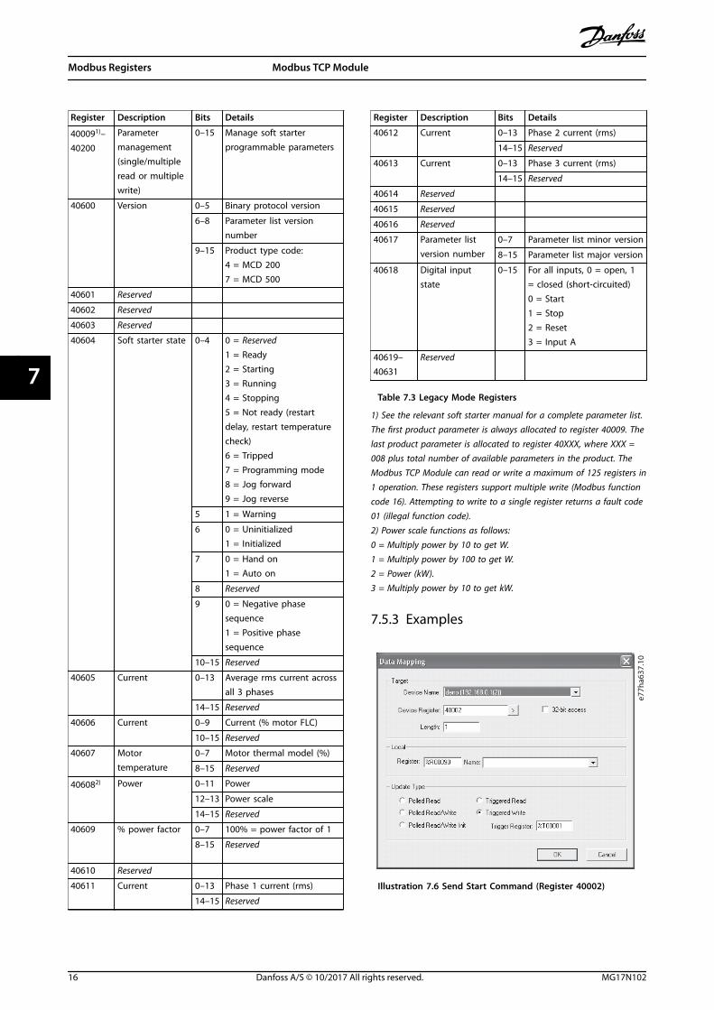
Table 7.3 Legacy Mode Registers
1) See the relevant soft starter manual for a complete parameter list.The first product parameter is always allocated to register 40009. Thelast product parameter is allocated to register 40XXX, where XXX =008 plus total number of available parameters in the product. TheModbus TCP Module can read or write a maximum of 125 registers in1 operation. These registers support multiple write (Modbus functioncode 16). Attempting to write to a single register returns a fault code01 (illegal function code).2) Power scale functions as follows:0 = Multiply power by 10 to get W.1 = Multiply power by 100 to get W.2 = Power (kW).3 = Multiply power by 10 to get kW.
7.5.3 Examplese7
7ha6
37.1
0
Illustration 7.6 Send Start Command (Register 40002)
Modbus Registers Modbus TCP Module
16 Danfoss A/S © 10/2017 All rights reserved. MG17N102
77
e77h
a638
.10
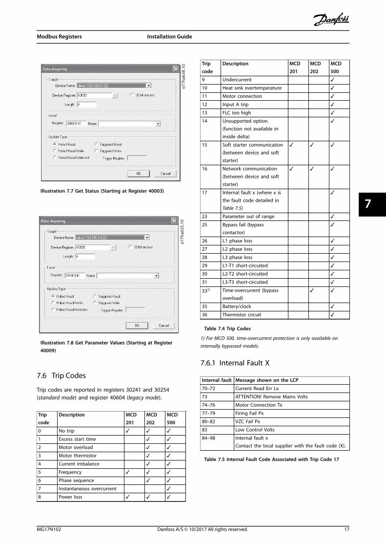
Illustration 7.7 Get Status (Starting at Register 40003)
e77h
a635
.10
Illustration 7.8 Get Parameter Values (Starting at Register40009)
7.6 Trip Codes
Trip codes are reported in registers 30241 and 30254(standard mode) and register 40604 (legacy mode).
Tripcode
Description MCD201
MCD202
MCD500
0 No trip ✓ ✓ ✓1 Excess start time ✓ ✓2 Motor overload ✓ ✓3 Motor thermistor ✓ ✓4 Current imbalance ✓ ✓5 Frequency ✓ ✓ ✓6 Phase sequence ✓ ✓7 Instantaneous overcurrent ✓8 Power loss ✓ ✓ ✓
Tripcode
Description MCD201
MCD202
MCD500
9 Undercurrent ✓10 Heat sink overtemperature ✓11 Motor connection ✓12 Input A trip ✓13 FLC too high ✓14 Unsupported option
(function not available ininside delta)
✓
15 Soft starter communication(between device and softstarter)
✓ ✓ ✓
16 Network communication(between device and softstarter)
✓ ✓ ✓
17 Internal fault x (where x isthe fault code detailed inTable 7.5)
✓
23 Parameter out of range ✓25 Bypass fail (bypass
contactor) ✓
26 L1 phase loss ✓27 L2 phase loss ✓28 L3 phase loss ✓29 L1-T1 short-circuited ✓30 L2-T2 short-circuited ✓31 L3-T3 short-circuited ✓331) Time-overcurrent (bypass
overload) ✓ ✓
35 Battery/clock ✓36 Thermistor circuit ✓
Table 7.4 Trip Codes
1) For MCD 500, time-overcurrent protection is only available oninternally bypassed models.
7.6.1 Internal Fault X
Internal fault Message shown on the LCP
70–72 Current Read Err Lx
73 ATTENTION! Remove Mains Volts
74–76 Motor Connection Tx
77–79 Firing Fail Px
80–82 VZC Fail Px
83 Low Control Volts
84–98 Internal fault xContact the local supplier with the fault code (X).
Table 7.5 Internal Fault Code Associated with Trip Code 17
Modbus Registers Installation Guide
MG17N102 Danfoss A/S © 10/2017 All rights reserved. 17
7 7
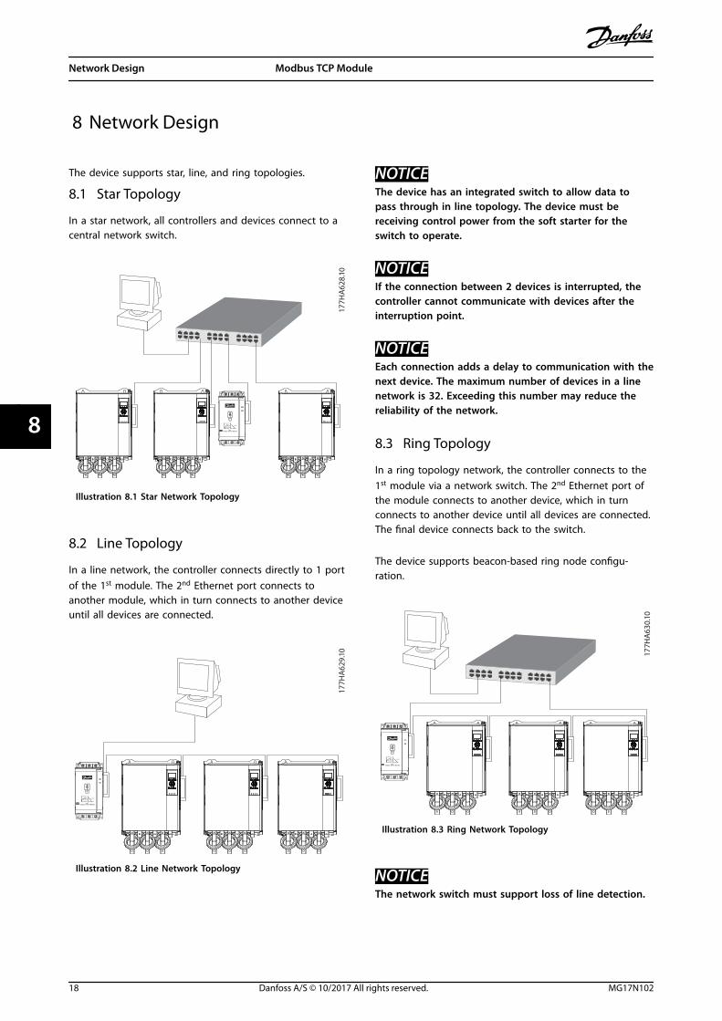
8 Network Design
The device supports star, line, and ring topologies.
8.1 Star Topology
In a star network, all controllers and devices connect to acentral network switch.
177H
A62
8.10
Illustration 8.1 Star Network Topology
8.2 Line Topology
In a line network, the controller connects directly to 1 portof the 1st module. The 2nd Ethernet port connects toanother module, which in turn connects to another deviceuntil all devices are connected.
177H
A62
9.10
Illustration 8.2 Line Network Topology
NOTICEThe device has an integrated switch to allow data topass through in line topology. The device must bereceiving control power from the soft starter for theswitch to operate.
NOTICEIf the connection between 2 devices is interrupted, thecontroller cannot communicate with devices after theinterruption point.
NOTICEEach connection adds a delay to communication with thenext device. The maximum number of devices in a linenetwork is 32. Exceeding this number may reduce thereliability of the network.
8.3 Ring Topology
In a ring topology network, the controller connects to the1st module via a network switch. The 2nd Ethernet port ofthe module connects to another device, which in turnconnects to another device until all devices are connected.The final device connects back to the switch.
The device supports beacon-based ring node configu-ration.
177H
A63
0.10
Illustration 8.3 Ring Network Topology
NOTICEThe network switch must support loss of line detection.
Network Design Modbus TCP Module
18 Danfoss A/S © 10/2017 All rights reserved. MG17N102
88
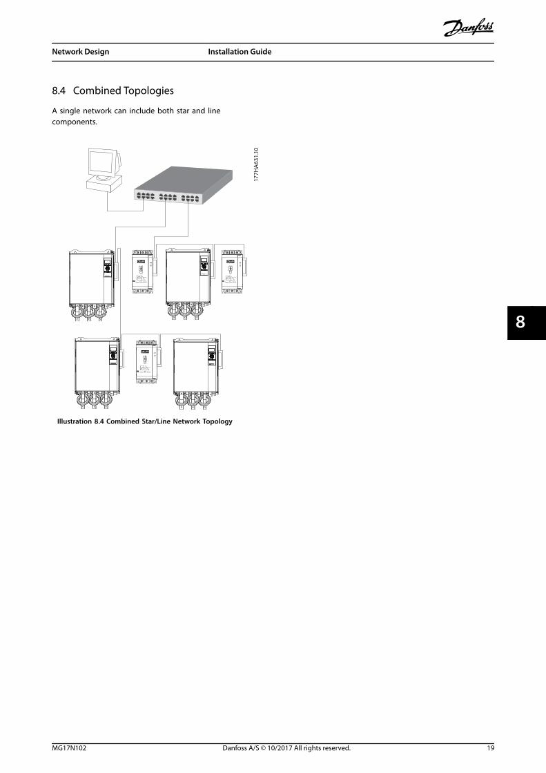
8.4 Combined Topologies
A single network can include both star and linecomponents.
177H
A63
1.10
Illustration 8.4 Combined Star/Line Network Topology
Network Design Installation Guide
MG17N102 Danfoss A/S © 10/2017 All rights reserved. 19
8 8
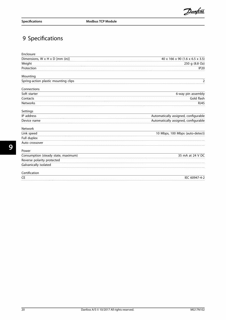
9 Specifications
EnclosureDimensions, W x H x D [mm (in)] 40 x 166 x 90 (1.6 x 6.5 x 3.5)Weight 250 g (8.8 Oz)Protection IP20
MountingSpring-action plastic mounting clips 2
ConnectionsSoft starter 6-way pin assemblyContacts Gold flashNetworks RJ45
SettingsIP address Automatically assigned, configurableDevice name Automatically assigned, configurable
NetworkLink speed 10 Mbps, 100 Mbps (auto-detect)Full duplexAuto crossover
PowerConsumption (steady state, maximum) 35 mA at 24 V DCReverse polarity protectedGalvanically isolated
CertificationCE IEC 60947-4-2
Specifications Modbus TCP Module
20 Danfoss A/S © 10/2017 All rights reserved. MG17N102
99
Index
AAbbreviations........................................................................................... 3
Additional resources.............................................................................. 3
Approvals................................................................................................... 3
Auto-on mode.......................................................................................... 4
BBusbar......................................................................................................... 4
CCable
category................................................................................................. 8Ethernet cable..................................................................................... 8
CapacitorsPower factor correction capacitor................................................ 4
Certifications............................................................................................. 3
Connections........................................................................................... 20
ContactorsBypass contactor................................................................................ 4Main contactor.................................................................................... 5
Conventions.............................................................................................. 3
DDimensions............................................................................................. 20
EElectromagnetic interference............................................................. 8
Ethernet attribute................................................................................... 9
HHeat sink..................................................................................................... 4
IInputs
Remote................................................................................................... 4
Installing the Modbus TCP module.................................................. 6
Intended use............................................................................................. 3
Internal fault code................................................................................ 17
IP address....................................................................................... 8, 9, 20
LLED
Description......................................................................................... 11LED........................................................................................................... 3Name.................................................................................................... 11Status.................................................................................................... 11
Legacy mode.......................................................................................... 12
MMAC address............................................................................................. 8
Motorconnection............................................................................................ 5
NNetwork
Auto crossover.................................................................................. 20Full duplex.......................................................................................... 20Line........................................................................................................ 18Link speed........................................................................................... 20Ring....................................................................................................... 18Star........................................................................................................ 18
OOperating mode................................................................................... 12
PParameter management.................................................................... 12
QQualified personnel........................................................................... 3, 4
RRemoving the Modbus TCP Module................................................ 6
Reset mode............................................................................................... 7
SStandard mode...................................................................................... 12
Subnet mask............................................................................................. 9
Supply..................................................................................................... 4, 5
Symbols...................................................................................................... 3
TTerminals
A1............................................................................................................. 7N2............................................................................................................. 7
UUnintended start..................................................................................... 4
WWeight...................................................................................................... 20
Index Installation Guide
MG17N102 Danfoss A/S © 10/2017 All rights reserved. 21

Danfoss can accept no responsibility for possible errors in catalogues, brochures and other printed material. Danfoss reserves the right to alter its products without notice. This also applies toproducts already on order provided that such alterations can be made without subsequential changes being necessary in specifications already agreed. All trademarks in this material are propertyof the respective companies. Danfoss and the Danfoss logotype are trademarks of Danfoss A/S. All rights reserved.
Danfoss A/SUlsnaes 1DK-6300 Graastenvlt-drives.danfoss.com
*MG17N102*175R1139 MG17N102 10/2017