System Installation Guide - HVAC Parts Online, Heating and Air

© 2010 Taco Electronic Solutions, Inc. 1
Installation Guide 502-022
CCU1 Chiller ControlSelf-Contained Interoperable Controller Model UCP-1
SUPERSEDES: September 1, 2010 EFFECTIVE: September 23, 2010Plant ID: 001-3979
Table of Contents
CCU1 . . . . . . . . . . . . . . . . . . . . . . . . . . . . . . . . . . . . . . 3Overview . . . . . . . . . . . . . . . . . . . . . . . . . . . . . . . . . 3Features. . . . . . . . . . . . . . . . . . . . . . . . . . . . . . . . . . 3
Representations and Warranties . . . . . . . . . . . . . . . . . 3
Applicable Documentation . . . . . . . . . . . . . . . . . . . . . . 4
Installation Instructions. . . . . . . . . . . . . . . . . . . . . . . . . 5Precautions . . . . . . . . . . . . . . . . . . . . . . . . . . . . . . . 5General . . . . . . . . . . . . . . . . . . . . . . . . . . . . . . . . . . 5Static Electricity . . . . . . . . . . . . . . . . . . . . . . . . . . . . 5Location . . . . . . . . . . . . . . . . . . . . . . . . . . . . . . . . . . 5FCC Compliance . . . . . . . . . . . . . . . . . . . . . . . . . . . 5
Before Installing . . . . . . . . . . . . . . . . . . . . . . . . . . . . . . 5About this Document . . . . . . . . . . . . . . . . . . . . . . . . 5Inspecting the Equipment . . . . . . . . . . . . . . . . . . . . 6What is Not Included with this Equipment . . . . . . . . 6Equipment Location . . . . . . . . . . . . . . . . . . . . . . . . . 6Selecting a Power Source . . . . . . . . . . . . . . . . . . . . 6
Installation. . . . . . . . . . . . . . . . . . . . . . . . . . . . . . . . . . . 6Mounting the Device. . . . . . . . . . . . . . . . . . . . . . . . .6Routing Cabling to the Device . . . . . . . . . . . . . . . . .7Grounding the Device. . . . . . . . . . . . . . . . . . . . . . . .7
Wiring Information. . . . . . . . . . . . . . . . . . . . . . . . . . . . . 8Connecting Input Devices. . . . . . . . . . . . . . . . . . . .10Connecting Output Devices . . . . . . . . . . . . . . . . . .11Other Connections . . . . . . . . . . . . . . . . . . . . . . . . .11
Specifications . . . . . . . . . . . . . . . . . . . . . . . . . . . . . . . 12Electrical . . . . . . . . . . . . . . . . . . . . . . . . . . . . . . . . .12Mechanical . . . . . . . . . . . . . . . . . . . . . . . . . . . . . . .13
Troubleshooting . . . . . . . . . . . . . . . . . . . . . . . . . . . . . 14Diagnostic LEDs. . . . . . . . . . . . . . . . . . . . . . . . . . .14Troubleshooting Tips . . . . . . . . . . . . . . . . . . . . . . .15

iWorX CCU1
2 502-022, Effective: September 23, 2010 © 2010 Taco Electronic Solutions, Inc.
THIS PAGE LEFT BLANK INTENTIONALLY
iWorX CCU1
502-022, Effective: September 23, 2010 3 © 2010 Taco Electronic Solutions, Inc.
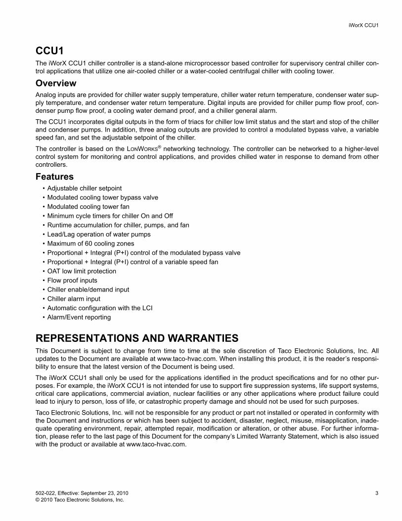
CCU1The iWorX CCU1 chiller controller is a stand-alone microprocessor based controller for supervisory central chiller con-trol applications that utilize one air-cooled chiller or a water-cooled centrifugal chiller with cooling tower.
OverviewAnalog inputs are provided for chiller water supply temperature, chiller water return temperature, condenser water sup-ply temperature, and condenser water return temperature. Digital inputs are provided for chiller pump flow proof, con-denser pump flow proof, a cooling water demand proof, and a chiller general alarm.
The CCU1 incorporates digital outputs in the form of triacs for chiller low limit status and the start and stop of the chiller and condenser pumps. In addition, three analog outputs are provided to control a modulated bypass valve, a variable speed fan, and set the adjustable setpoint of the chiller.
The controller is based on the LONWORKS® networking technology. The controller can be networked to a higher-level control system for monitoring and control applications, and provides chilled water in response to demand from other controllers.
Features• Adjustable chiller setpoint• Modulated cooling tower bypass valve• Modulated cooling tower fan• Minimum cycle timers for chiller On and Off• Runtime accumulation for chiller, pumps, and fan• Lead/Lag operation of water pumps• Maximum of 60 cooling zones• Proportional + Integral (P+I) control of the modulated bypass valve• Proportional + Integral (P+I) control of a variable speed fan• OAT low limit protection• Flow proof inputs• Chiller enable/demand input• Chiller alarm input• Automatic configuration with the LCI• Alarm/Event reporting
REPRESENTATIONS AND WARRANTIESThis Document is subject to change from time to time at the sole discretion of Taco Electronic Solutions, Inc. All updates to the Document are available at www.taco-hvac.com. When installing this product, it is the reader’s responsi-bility to ensure that the latest version of the Document is being used.
The iWorX CCU1 shall only be used for the applications identified in the product specifications and for no other pur-poses. For example, the iWorX CCU1 is not intended for use to support fire suppression systems, life support systems, critical care applications, commercial aviation, nuclear facilities or any other applications where product failure could lead to injury to person, loss of life, or catastrophic property damage and should not be used for such purposes.
Taco Electronic Solutions, Inc. will not be responsible for any product or part not installed or operated in conformity with the Document and instructions or which has been subject to accident, disaster, neglect, misuse, misapplication, inade-quate operating environment, repair, attempted repair, modification or alteration, or other abuse. For further informa-tion, please refer to the last page of this Document for the company’s Limited Warranty Statement, which is also issued with the product or available at www.taco-hvac.com.
iWorX CCU1
4 502-022, Effective: September 23, 2010 © 2010 Taco Electronic Solutions, Inc.
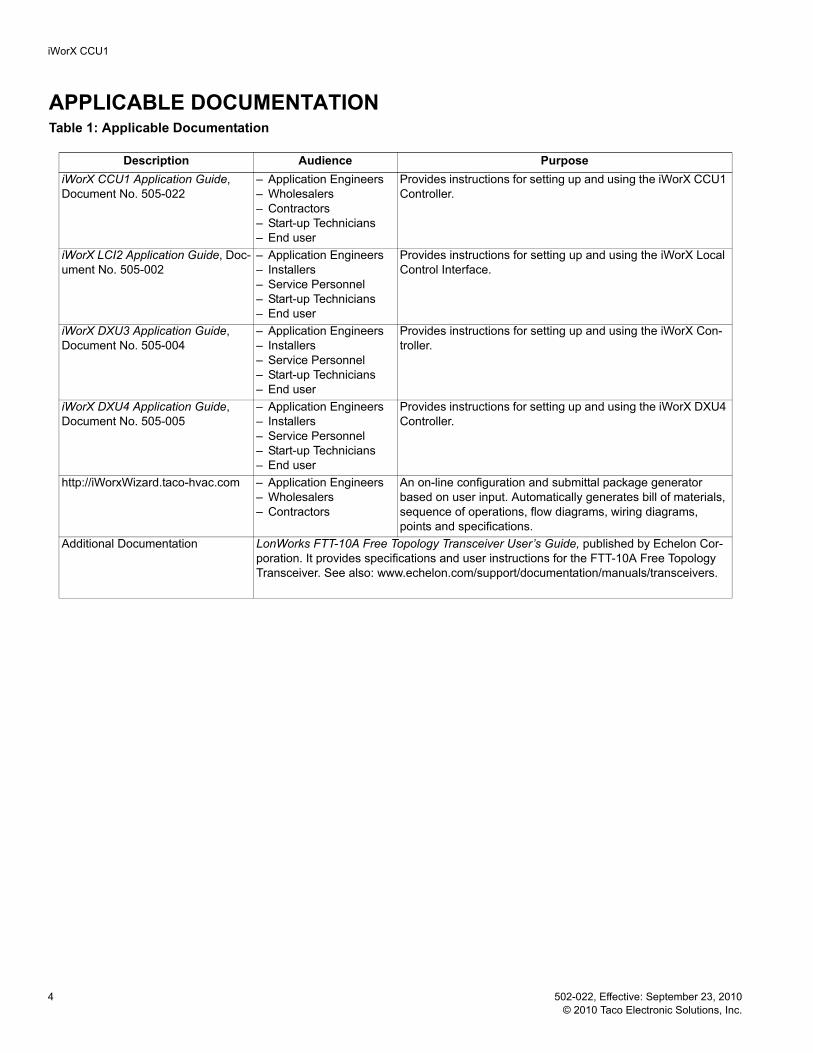
APPLICABLE DOCUMENTATIONTable 1: Applicable Documentation
Description Audience PurposeiWorX CCU1 Application Guide, Document No. 505-022
– Application Engineers– Wholesalers– Contractors– Start-up Technicians– End user
Provides instructions for setting up and using the iWorX CCU1 Controller.
iWorX LCI2 Application Guide, Doc-ument No. 505-002
– Application Engineers– Installers– Service Personnel– Start-up Technicians– End user
Provides instructions for setting up and using the iWorX Local Control Interface.
iWorX DXU3 Application Guide, Document No. 505-004
– Application Engineers– Installers– Service Personnel– Start-up Technicians– End user
Provides instructions for setting up and using the iWorX Con-troller.
iWorX DXU4 Application Guide, Document No. 505-005
– Application Engineers– Installers– Service Personnel– Start-up Technicians– End user
Provides instructions for setting up and using the iWorX DXU4 Controller.
http://iWorxWizard.taco-hvac.com – Application Engineers– Wholesalers– Contractors
An on-line configuration and submittal package generator based on user input. Automatically generates bill of materials, sequence of operations, flow diagrams, wiring diagrams, points and specifications.
Additional Documentation LonWorks FTT-10A Free Topology Transceiver User’s Guide, published by Echelon Cor-poration. It provides specifications and user instructions for the FTT-10A Free Topology Transceiver. See also: www.echelon.com/support/documentation/manuals/transceivers.
iWorX CCU1
502-022, Effective: September 23, 2010 5 © 2010 Taco Electronic Solutions, Inc.
INSTALLATION INSTRUCTIONSPrecautionsGeneral
This symbol is intended to alert the user to the presence of important installation and maintenance (servic-ing) instructions in the literature accompanying the equipment.
WARNING: Electrical shock hazard. Disconnect ALL power sources when installing or servicing this equipment to prevent electrical shock or equipment damage.
Make all wiring connections in accordance with these instructions and in accordance with pertinent national and local electrical codes. Use only copper conductors.
Static ElectricityStatic charges produce voltages that can damage this equipment. Follow these static electricity precautions when han-dling this equipment.
• Work in a static free area.• Touch a known, securely grounded object to discharge any charge you may have accumulated.• Use a wrist strap when handling printed circuit boards. The strap must be secured to earth ground.
LocationAvoid locations where corrosive fumes, excessive moisture, vibration or explosive vapors are present.
Avoid electrical noise interference. Do not install near large contactors, electrical machinery, or welding equipment.
This equipment is suitable for indoor or outdoor use. Preferably, or as required by National Electrical Code, the unit is intended to be installed within an electrical control enclosure. Operate where ambient temperatures do not exceed 140 °F (60 °C) or fall below 32 °F (0 °C) and relative humidity does not exceed 90%, non-condensing.
FCC ComplianceThis equipment has been tested and found to comply with the limits for a Class A digital device, pursuant to Part 15 of the FCC rules. These limits are designed to provide reasonable protection against harmful interference. This equip-ment can radiate radio frequency energy and, if not installed and used in accordance with the instructions, may cause harmful interference to radio communications. However, there is no guarantee that interference will not occur in a par-ticular installation. If this equipment does cause harmful interference to radio or television reception, which can be determined by turning the equipment off and on, the user is encouraged to try to correct the interference by one or more of the following measures:
• Reorient or relocate the receiving antenna.• Increase the separation between the equipment and the receiver.• Connect the equipment to a power source different from that to which the receiver is connected.• Consult the equipment supplier or an experienced radio/TV technician for help.
You are cautioned that any changes or modifications to this equipment not expressly approved in these instructions could void your authority to operate this equipment in the United States.
BEFORE INSTALLINGAbout this DocumentThe instructions in this manual are for the CCU1 module, which supports one central plant consisting of one air-cooled chiller or one water-cooled chiller with cooling tower.

iWorX CCU1
6 502-022, Effective: September 23, 2010 © 2010 Taco Electronic Solutions, Inc.
Inspecting the EquipmentInspect the shipping carton for damage. If damaged, notify the carrier immediately. Inspect the equipment for damage. Return damaged equipment to the supplier.
What is Not Included with this Equipment• A power source for the equipment electronics and peripheral devices.• Tools necessary to install, troubleshoot and service the equipment.• The screws or DIN rail needed to mount the device.• Peripheral devices, such as sensors, actuators, etc.• Cabling, cabling raceway, and fittings necessary to connect this equipment to the power source, FTT-10A network
and peripheral devices.
Equipment LocationAbide by all warnings regarding equipment location provided earlier in this document.
Optimally, the equipment should be installed within a secure enclosure.
If the equipment is to be installed outdoors, it must be contained within a protective enclosure. The enclosure must maintain internal temperature and humidity within the ranges specified for this equipment.
The equipment must be installed within 500 feet of all input peripherals (smoke detectors, sensors, etc.) that will be connected to the equipment.
Selecting a Power SourceThis equipment requires a UL recognized Class 2 external power source (not supplied) to operate. The controller power input requires a voltage of 24 Volts AC.
To calculate power source current requirements, add the power consumption of all peripheral devices to that of the controller.
The controller and triac output loads can use the same power source. If both are using the same power source, the loads must have EMF protection. This protection can be integral to the load, or installed in the 24 VAC wiring across the load’s coil.
To provide necessary RFI and transient protection, the controller’s ground (GND) pin (T40) must be connected to earth ground or the earth ground of the packaged unit’s enclosure ground. Failure to properly ground the controller may cause it to exceed FCC limits. Excessive noise could also produce inaccurate sensor data. The power source must be capable of operating with this connection to ground.
INSTALLATIONWarning: Electrical shock hazard. To prevent electrical shock or equipment damage, disconnect ALL power sources to controllers and loads before installing or servicing this equipment or modifying any wir-ing.
Mounting the Device1.Select a mounting location. Enclosure mounting is recommended. 2.Hold the controller on the panel you wish to mount it on. With a marker or pencil mark the mounting locations on
the panel. 3.Using a small drill bit pre-drill the mounting holes. 4.Using two #6 pan head screws, mount the controller to the panel. 5.Wire the controller (See Routing Cabling to the Device).
iWorX CCU1
502-022, Effective: September 23, 2010 7 © 2010 Taco Electronic Solutions, Inc.
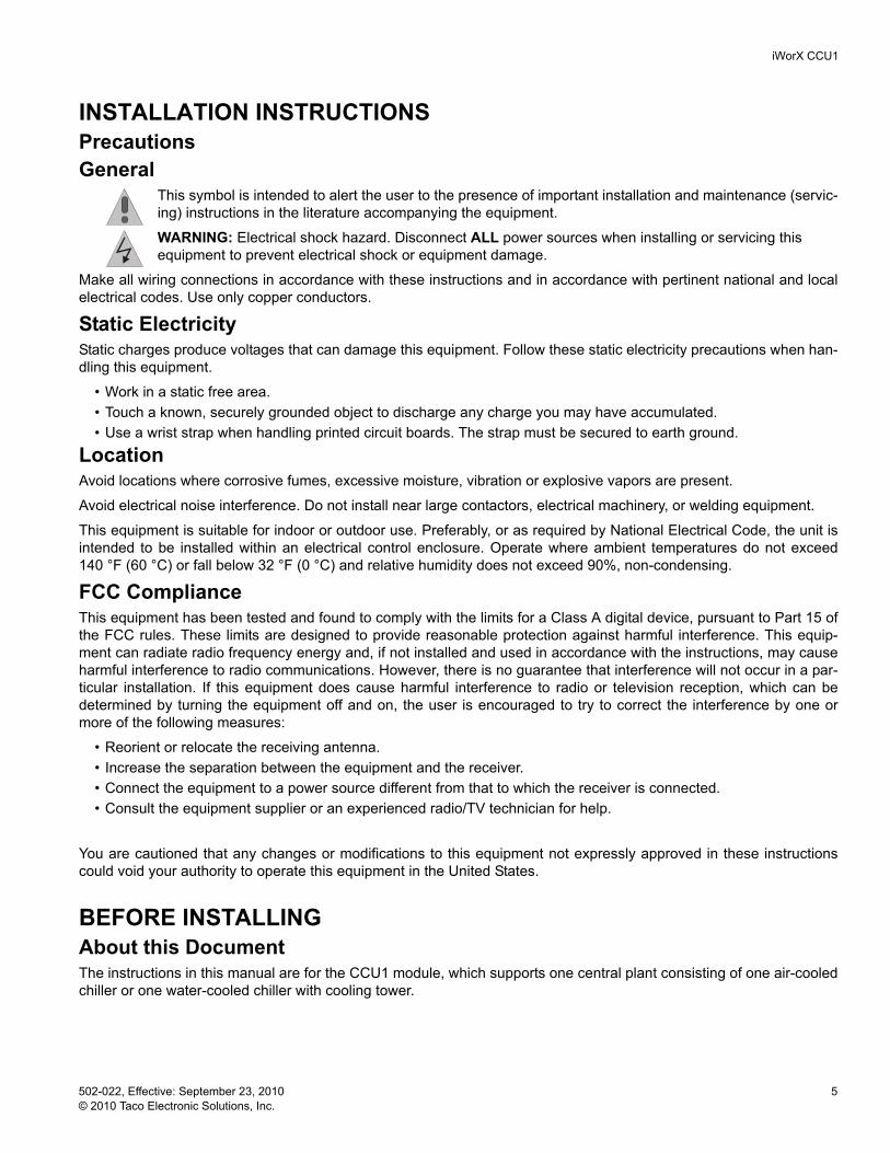
Figure 1: Mounting Dimensions
Routing Cabling to the DeviceCabling used to connect the power source and cabling used to connect the FTT-10A network must remain separated within the control enclosure and wiring conduit.
Grounding the DeviceThe ground terminal (T40) must be securely connected to earth ground. Failure to properly ground this equipment will result in improper operation. Improper grounding may also increase the risk of electrical shock and may increase the possibility of interference with radio/TV reception.
For best performance, connect the power supply common terminal (T38) to the same external point as the ground terminal (T40).
iWorX CCU1
8 502-022, Effective: September 23, 2010 © 2010 Taco Electronic Solutions, Inc.
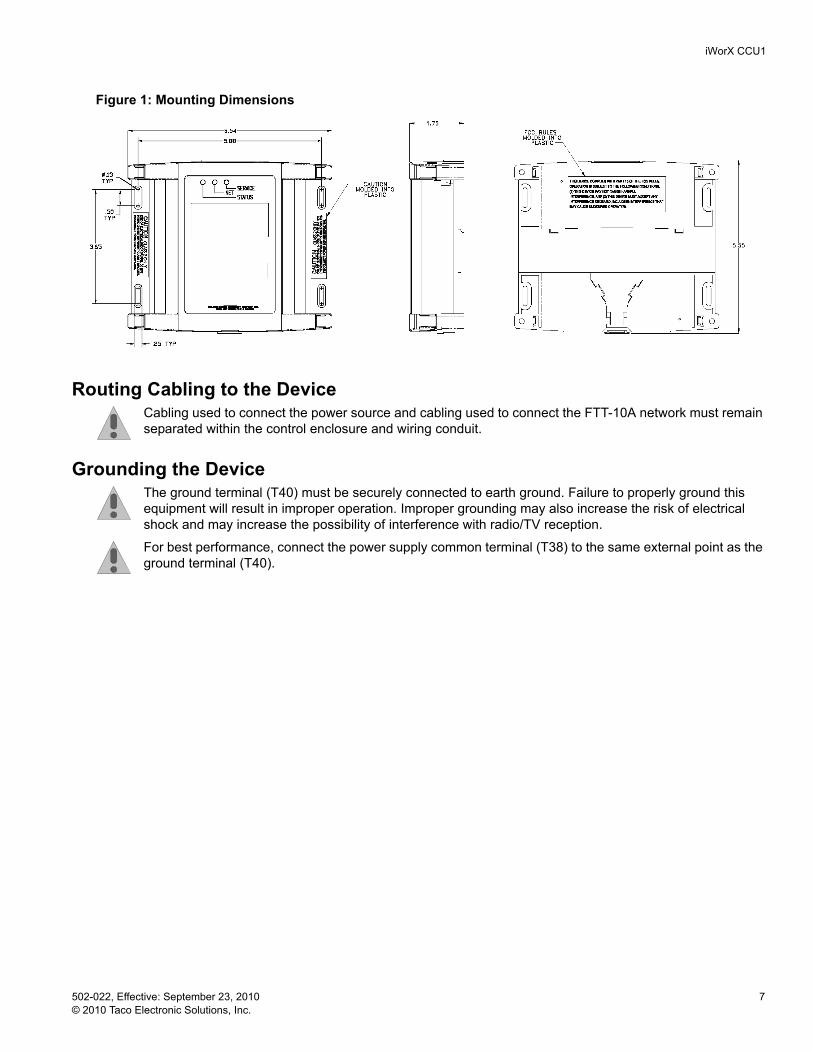
WIRING INFORMATIONWARNING: Terminals 6, 9, 12, 15, 18, 33, 36, and 38 are connected internally on all CCU1 controllers. Disconnect ALL power sources when installing or servicing this equipment to prevent electrical shock or equipment damage.
Figure 2: Wiring Diagram for Power Sourcing applications
iWorX CCU1
502-022, Effective: September 23, 2010 9 © 2010 Taco Electronic Solutions, Inc.
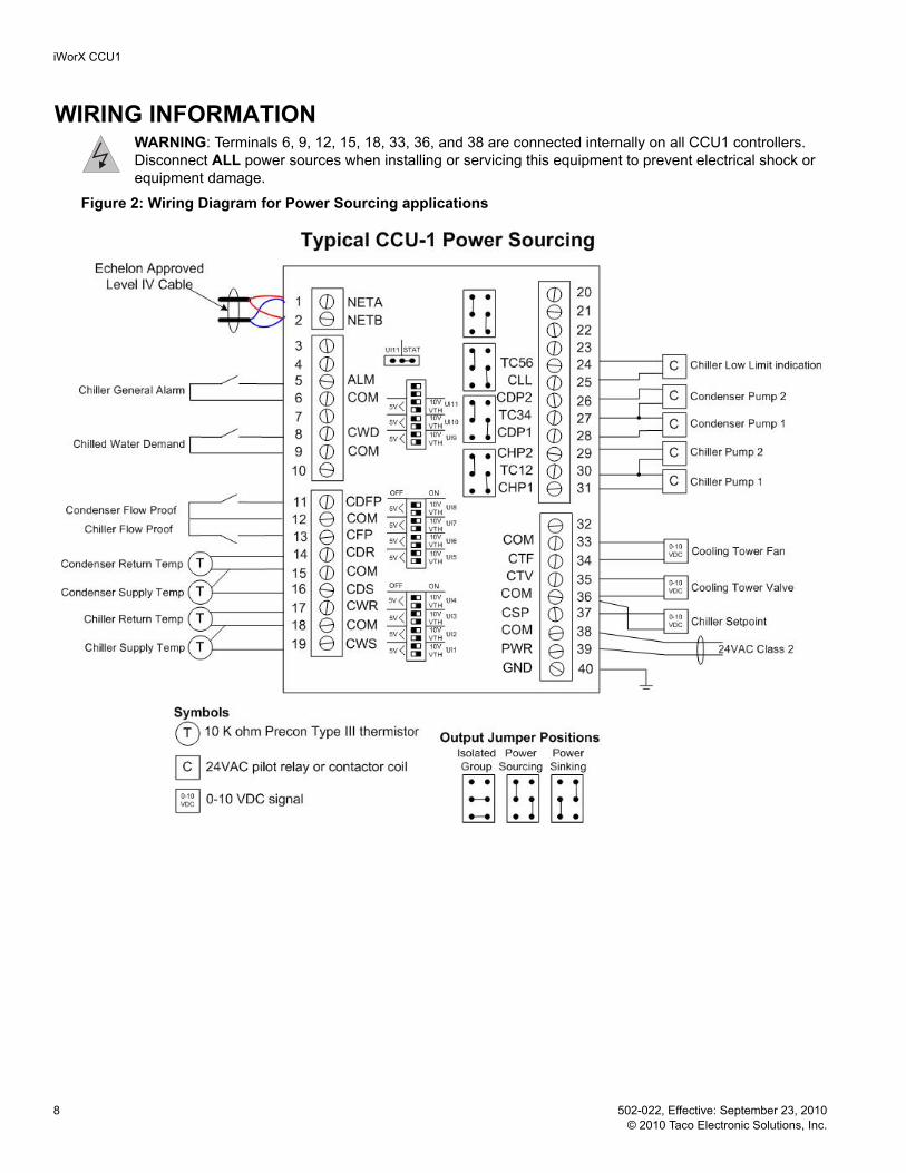
Figure 3: Wiring Diagram for Power Sinking applications
iWorX CCU1
10 502-022, Effective: September 23, 2010 © 2010 Taco Electronic Solutions, Inc.
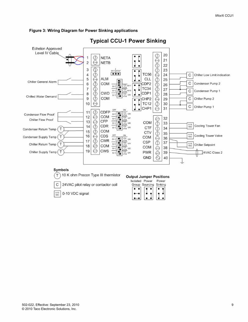
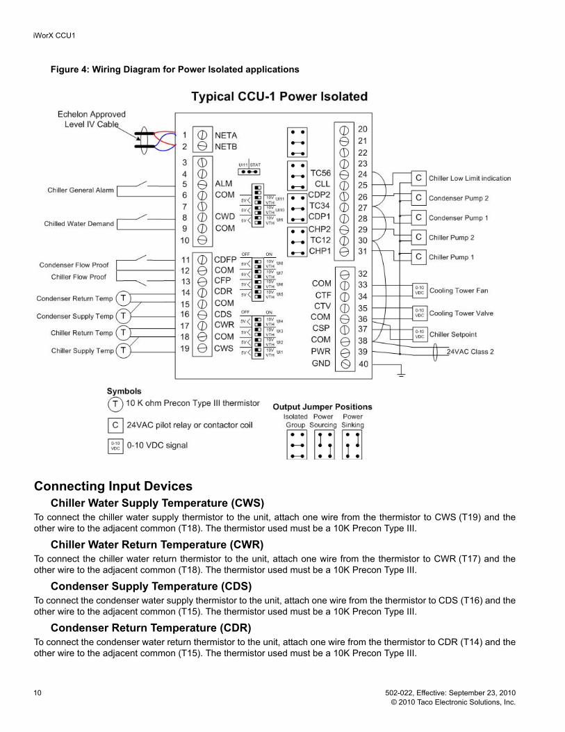
Figure 4: Wiring Diagram for Power Isolated applications
Connecting Input DevicesChiller Water Supply Temperature (CWS)
To connect the chiller water supply thermistor to the unit, attach one wire from the thermistor to CWS (T19) and the other wire to the adjacent common (T18). The thermistor used must be a 10K Precon Type III.
Chiller Water Return Temperature (CWR)To connect the chiller water return thermistor to the unit, attach one wire from the thermistor to CWR (T17) and the other wire to the adjacent common (T18). The thermistor used must be a 10K Precon Type III.
Condenser Supply Temperature (CDS)To connect the condenser water supply thermistor to the unit, attach one wire from the thermistor to CDS (T16) and the other wire to the adjacent common (T15). The thermistor used must be a 10K Precon Type III.
Condenser Return Temperature (CDR)To connect the condenser water return thermistor to the unit, attach one wire from the thermistor to CDR (T14) and the other wire to the adjacent common (T15). The thermistor used must be a 10K Precon Type III.

iWorX CCU1
502-022, Effective: September 23, 2010 11 © 2010 Taco Electronic Solutions, Inc.
Chiller Flow Proof (CFP)To connect the chiller flow proof switch to the digital input, attach one wire of the contact to CFP (T13) and the other wire to the adjacent common (T12). This must be a dry contact, normally open switch which closes when flow is detected. If a flow proof switch is not installed, the terminals should be connected with a jumper wire.
Condenser Flow Proof (CDFP)To connect the condenser flow proof switch to the digital input, attach one wire of the contact to CDFP (T11) and the other wire to the adjacent common (T12). This must be a dry contact, normally open switch which closes when flow is detected. If a flow proof switch is not installed, the terminals should be connected with a jumper wire.
Chiller General Alarm (ALM)To connect the chiller’s general alarm output to the digital input, attach one wire of the contact to ALM (T5) and the other wire to the adjacent common (T6). This output from the chiller must act as a dry contact, normally open switch.
Chilled Water Demand (CWD)To connect the demand switch to the digital input, attach one wire of the contact to CWD (T8) and the other wire to the adjacent common (T9). This must be a dry contact, normally open switch.
Connecting Output DevicesChiller Pumps 1 & 2 (CHP1, CHP2)
The outputs for the pumps must be connected to 24 VAC pilot relays if the load is greater than 1 Amp for each pump. If the load is less than 1 Amp, connect pump 1 to CHP1 (T31) and TC12 (T30), and connect pump 2 to CHP2 (T29) and TC12 (T30).
Condenser Pumps 1 & 2 (CDP1, CDP2)The outputs for the pumps must be connected to 24 VAC pilot relays if the load is greater than 1 Amp for each pump. If the load is less than 1 Amp, connect pump 1 to CDP1 (T28) and TC34 (T27), and connect pump 2 to CDP2 (T26) and TC34 (T27).
Chiller Low Limit (CLL)The output for the chiller low limit interface must be connected to a 24 VAC pilot relays if the load is greater than 1 Amp. If the load is less than 1 Amp, connect the chiller's low limit input to CLL (T25) and TC56 (T24).
Chiller Setpoint Adjustment (CSP)The chiller setpoint adjustment output can be set to 0-10 VDC max through the control logic. Connect the positive wire from the chiller’s setpoint adjustment input to CSP (T37) and the other wire to the adjacent common (T36).
Cooling Tower Valve (CTV)The cooling tower bypass valve output can be set to 0-10 VDC max through the control logic. Connect the positive wire from the valve actuator to CTV (T35) and the other wire to the adjacent common (T36).
Cooling Tower Fan (CTF)The cooling tower fan output can be set to 0-10 VDC max through the control logic. Connect the positive wire from the fan actuator to CTF (T34) and the other wire to the adjacent common (T33).
Other ConnectionsNetwork (LON)
Network wiring must be twisted pair. One network wire must be connected to terminal NETA (T1) and the other network wire must be connected to terminal NETB (T2). Polarity is not an issue since an FTT-10A network is used for commu-nications.
Power (PWR)Connect one output wire from a 24 VAC power supply to PWR (T39) and the other output wire from the power supply to the adjacent common terminal (T38).
iWorX CCU1
12 502-022, Effective: September 23, 2010 © 2010 Taco Electronic Solutions, Inc.
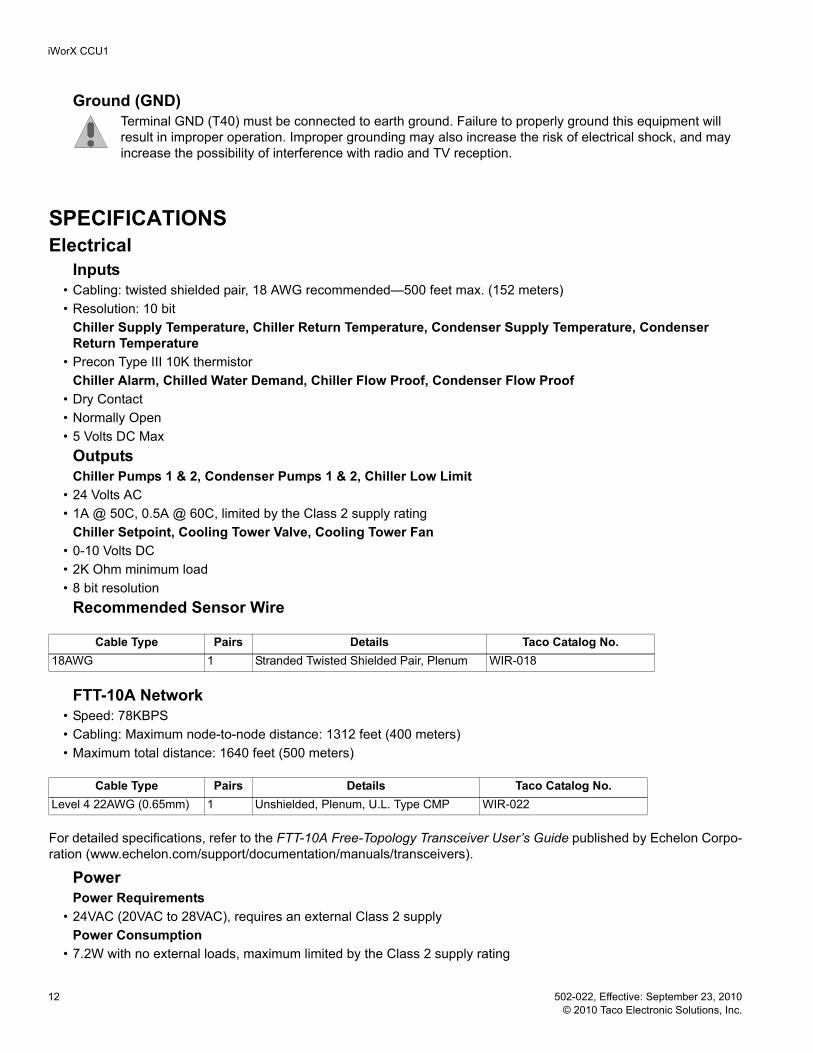
Ground (GND)Terminal GND (T40) must be connected to earth ground. Failure to properly ground this equipment will result in improper operation. Improper grounding may also increase the risk of electrical shock, and may increase the possibility of interference with radio and TV reception.
SPECIFICATIONSElectrical
Inputs• Cabling: twisted shielded pair, 18 AWG recommended—500 feet max. (152 meters)• Resolution: 10 bit
Chiller Supply Temperature, Chiller Return Temperature, Condenser Supply Temperature, Condenser Return Temperature
• Precon Type III 10K thermistorChiller Alarm, Chilled Water Demand, Chiller Flow Proof, Condenser Flow Proof
• Dry Contact• Normally Open• 5 Volts DC Max
Outputs Chiller Pumps 1 & 2, Condenser Pumps 1 & 2, Chiller Low Limit
• 24 Volts AC• 1A @ 50C, 0.5A @ 60C, limited by the Class 2 supply rating
Chiller Setpoint, Cooling Tower Valve, Cooling Tower Fan• 0-10 Volts DC• 2K Ohm minimum load• 8 bit resolution
Recommended Sensor Wire
FTT-10A Network• Speed: 78KBPS• Cabling: Maximum node-to-node distance: 1312 feet (400 meters)• Maximum total distance: 1640 feet (500 meters)
For detailed specifications, refer to the FTT-10A Free-Topology Transceiver User’s Guide published by Echelon Corpo-ration (www.echelon.com/support/documentation/manuals/transceivers).
PowerPower Requirements
• 24VAC (20VAC to 28VAC), requires an external Class 2 supplyPower Consumption
• 7.2W with no external loads, maximum limited by the Class 2 supply rating
Cable Type Pairs Details Taco Catalog No.18AWG 1 Stranded Twisted Shielded Pair, Plenum WIR-018
Cable Type Pairs Details Taco Catalog No.Level 4 22AWG (0.65mm) 1 Unshielded, Plenum, U.L. Type CMP WIR-022

iWorX CCU1
502-022, Effective: September 23, 2010 13 © 2010 Taco Electronic Solutions, Inc.
MechanicalHousing
• Dimensions: 5.55” (141mm) high, 6.54” (166 mm) wide, 1.75” deep (44 mm)• ABS
Weight • Controller Weight: 0.70 pounds (0.32 kilograms)• Shipping Weight: 1.0 pounds (0.46 kilograms)
Electronics• Processor: 3150 Neuron 10 MHz• Flash: 48 Kilobytes • SRAM: 8 Kilobytes • Termination: 0.197” (5.0 mm) Pluggable Terminal Blocks, 14-22 AWG
Environmental • Temperature: 32 °F to 140 °F (0 °C to 60 °C)• Humidity: 0 to 90%, non-condensing
Agency Listings• UL Listed for US and Canada, Energy Management Equipment PAZX and PAZX7.
Agency Compliances• FCC Part 15 Class A
iWorX CCU1
14 502-022, Effective: September 23, 2010 © 2010 Taco Electronic Solutions, Inc.
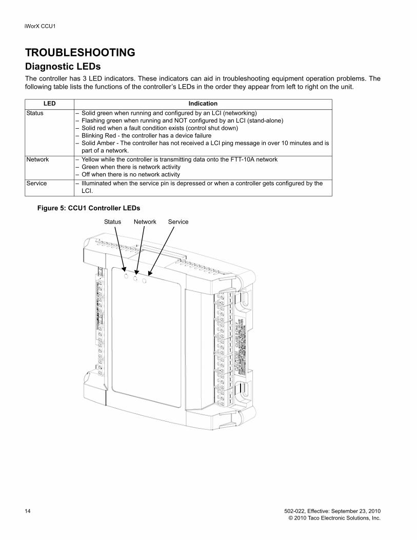
TROUBLESHOOTINGDiagnostic LEDsThe controller has 3 LED indicators. These indicators can aid in troubleshooting equipment operation problems. The following table lists the functions of the controller’s LEDs in the order they appear from left to right on the unit.
Figure 5: CCU1 Controller LEDs
Status Network Service
LED IndicationStatus – Solid green when running and configured by an LCI (networking)
– Flashing green when running and NOT configured by an LCI (stand-alone)– Solid red when a fault condition exists (control shut down)– Blinking Red - the controller has a device failure– Solid Amber - The controller has not received a LCI ping message in over 10 minutes and is
part of a network.Network – Yellow while the controller is transmitting data onto the FTT-10A network
– Green when there is network activity– Off when there is no network activity
Service – Illuminated when the service pin is depressed or when a controller gets configured by the LCI.

iWorX CCU1
502-022, Effective: September 23, 2010 15 © 2010 Taco Electronic Solutions, Inc.
Troubleshooting TipsThe following table provides tips on resolving common issues.
Getting HelpComponents within an iWorX CCU1 controller cannot be field repaired. If there is a problem with a controller, follow the steps below before contacting your local TES representative or TES technical service.
1.Make sure controllers are connected and communicating to desired devices.2.Record precise hardware setup indicating the following:
Version numbers of applications software.
Controller firmware version number.
A complete description of difficulties encountered.
Problem SolutionController is not running and Status LED is not illuminated.
No power to controller. Verify the voltage on the controller’s power connector (24 VAC).
How do I reset the controller? The controller can be reset by the LCI, or you can cycle power to the controller. Refer to the LCI documentation for more information on resetting the controller using the LCI.
Can my iWorX system contain multi-ple CCU1 controllers?
No, the system can only recognize one.
Thermistor readings fluctuate rapidly, sometimes by several degrees.
The controller may not be properly grounded. The controller’s ground (GND) pin (T40) must be connected to earth ground. Also ensure that the controller’s digital inputs are dry contacts and that no voltage is being applied or switched to the inputs.
How do I associate my other control-lers with the CCU1?
Use the CCU1’s grouping mechanism, specifically HVAC Setup --> Members on the CCU1 screen of the LCI.
What iWorX controllers can be part of a CCU1’s group?
Only FCU series, DXU series and HPU series controllers can be part of the CCU1's group and demand cooling from it.
Several controllers are requesting cooling, but the chiller and pumps have not been enabled.
The Zone Limit setting may be set higher than the number of zones that are currently requesting cooling. The chiller and pumps will not be enabled until the number of zones requesting cooling is greater than the Zone Limit setting.
If the number of controllers requesting cooling exceeds the Zone Limit setting, but the chiller is still not enabled, the outside air temperature may be less than the Outdoor Air Temp. Lockout setting.
I only have one chiller pump; how can I disable lead/lag operation?
The lead/lag function is built into the controller and cannot be disabled. However, you can wire both chiller pump outputs in parallel from the controller to the existing pump and the system will operate normally. The same can be done for the condenser pump outputs if you have only one condenser pump.
The LCI is reporting a dual pump fail-ure. How do I know which pumps have failed?
Check the pump alarms that precede the dual pump failure alarm. These two alarms will indicate which two pumps have failed, the chiller pumps or the condenser pumps.

iWorX CCU1
Printed in the USA iWorX and iView are trademarks of Taco, Inc. © 2010 Taco Electronic Solutions, Inc. LON, LONWORKS, & LONMARK are trademarks of Echelon Corporation
CONTROLS MADE EASY®
Taco Electronic Solutions, Inc., 1160 Cranston Street, Cranston, RI 02920 Telephone: (401) 942-8000 FAX: (401) 942-2360.
Taco (Canada), Ltd., 8450 Lawson Road, Unit #3, Milton, Ontario L9T 0J8. Telephone: 905/564-9422. FAX: 905/564-9436.
Taco Electronic Solutions, Inc. is a subsidiary of Taco, Inc. Visit our web site at: http://www.taco-hvac.com
Taco Electronic Solutions, Inc. (TES) will repair or replace without charge (at the company's option) any product or part which is proven defective under normal use within one (1) year from the date of start-up or one (1) year and six (6) months from date of shipment (whichever occurs first).
In order to obtain service under this warranty, it is the responsibility of the purchaser to promptly notify the local TES stocking distribu-tor or TES in writing and promptly deliver the subject product or part, delivery prepaid, to the stocking distributor. For assistance on war-ranty returns, the purchaser may either contact the local TES stocking distributor or TES. If the subject product or part contains no defect as covered in this warranty, the purchaser will be billed for parts and labor charges in effect at time of factory examination and repair.
Any TES product or part not installed or oper-ated in conformity with TES instructions or which has been subject to accident, disaster, neglect, misuse, misapplication, inadequate operating environment, repair, attempted repair, modification or alteration, or other abuse, will not be covered by this warranty.
TES products are not intended for use to sup-port fire suppression systems, life support sys-tems, critical care applications, commercial aviation, nuclear facilities or any other applica-tions where product failure could lead to injury to person, loss of life, or catastrophic property damage and should not be sold for such pur-poses.
If in doubt as to whether a particular product is suitable for use with a TES product or part, or for any application restrictions, consult the applicable TES instruction sheets or in the U.S. contact TES at 401-942-8000 and in Canada contact Taco (Canada) Limited at 905-564-9422.
TES reserves the right to provide replacement products and parts which are substantially simi-lar in design and functionally equivalent to the defective product or part. TES reserves the right to make changes in details of design, con-struction, or arrangement of materials of its products without notification.
TES OFFERS THIS WARRANTY IN LIEU OF ALL OTHER EXPRESS WARRANTIES. ANY WARRANTY IMPLIED BY LAW INCLUDING
WARRANTIES OF MERCHANTABILITY OR FITNESS IS IN EFFECT ONLY FOR THE DURATION OF THE EXPRESS WARRANTY SET FORTH IN THE FIRST PARAGRAPH ABOVE.
THE ABOVE WARRANTIES ARE IN LIEU OF ALL OTHER WARRANTIES, EXPRESS OR STATUTORY, OR ANY OTHER WARRANTY OBLIGATION ON THE PART OF TES.
TES WILL NOT BE LIABLE FOR ANY SPE-CIAL, INCIDENTAL, INDIRECT OR CONSE-QUENTIAL DAMAGES RESULTING FROM THE USE OF ITS PRODUCTS OR ANY INCI-DENTAL COSTS OF REMOVING OR REPLACING DEFECTIVE PRODUCTS.
This warranty gives the purchaser specific rights, and the purchaser may have other rights which vary from state to state. Some states do not allow limitations on how long an implied warranty lasts or on the exclusion of incidental or consequential damages, so these limitations or exclusions may not apply to you.
LIMITED WARRANTY STATEMENT
Notes: