Installation Guide Guía de instalación - … · 2014-09-29 · Installation Guide Guía de...
12
Installation Guide Guía de instalación HandDryerSupply.com | 804-859-2498 | http://www.handdryersupply.com HandDryerSupply.com | 804-859-2498 | http://www.handdryersupply.com
-
Upload
vuongduong -
Category
Documents
-
view
219 -
download
0
Transcript of Installation Guide Guía de instalación - … · 2014-09-29 · Installation Guide Guía de...
1
Installation GuideGuía de instalación
HandDryerSupply.com | 804-859-2498 | http://www.handdryersupply.com
HandDryerSupply.com | 804-859-2498 | http://www.handdryersupply.com
2
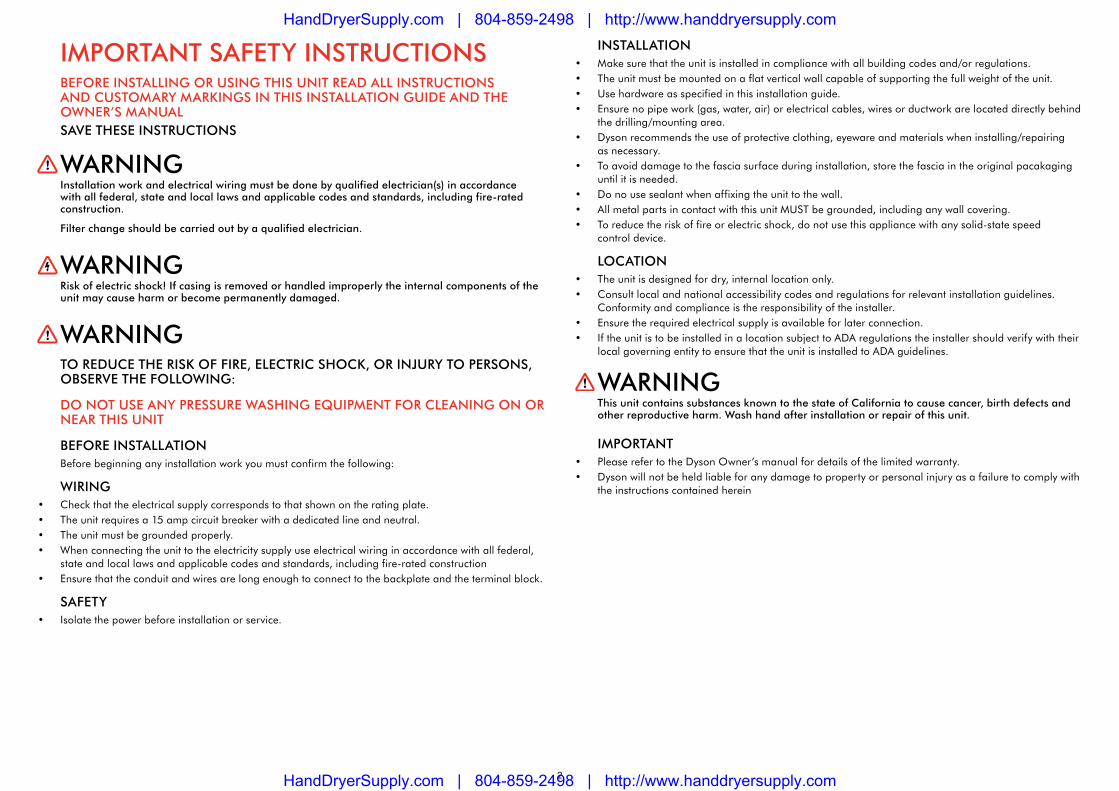
Important safety InstructIonsBefore InstaLLInG or usInG tHIs unIt reaD aLL InstructIons anD customary marKInGs In tHIs InstaLLatIon GuIDe anD tHe oWner’s manuaLsave tHese InstructIons
WarnInGInstallation work and electrical wiring must be done by qualified electrician(s) in accordance with all federal, state and local laws and applicable codes and standards, including fire-rated construction.
filter change should be carried out by a qualified electrician.
WarnInGrisk of electric shock! If casing is removed or handled improperly the internal components of the unit may cause harm or become permanently damaged.
WarnInGto reDuce tHe rIsK of fIre, eLectrIc sHocK, or InJury to persons, oBserve tHe foLLoWInG:
Do not use any pressure WasHInG eQuIpment for cLeanInG on or near tHIs unIt
Before InstaLLatIonBefore beginning any installation work you must confirm the following:
WIrInG• Check that the electrical supply corresponds to that shown on the rating plate. • The unit requires a 15 amp circuit breaker with a dedicated line and neutral.• The unit must be grounded properly.• When connecting the unit to the electricity supply use electrical wiring in accordance with all federal,
state and local laws and applicable codes and standards, including fire-rated construction• Ensure that the conduit and wires are long enough to connect to the backplate and the terminal block.
safety• Isolate the power before installation or service.
InstaLLatIon• Make sure that the unit is installed in compliance with all building codes and/or regulations.• The unit must be mounted on a flat vertical wall capable of supporting the full weight of the unit.• Use hardware as specified in this installation guide.• Ensure no pipe work (gas, water, air) or electrical cables, wires or ductwork are located directly behind
the drilling/mounting area.• Dyson recommends the use of protective clothing, eyeware and materials when installing/repairing
as necessary.• To avoid damage to the fascia surface during installation, store the fascia in the original pacakaging
until it is needed.• Do no use sealant when affixing the unit to the wall.• All metal parts in contact with this unit MUST be grounded, including any wall covering.• To reduce the risk of fire or electric shock, do not use this appliance with any solid-state speed
control device.
LocatIon• The unit is designed for dry, internal location only.• Consult local and national accessibility codes and regulations for relevant installation guidelines.
Conformity and compliance is the responsibility of the installer.• Ensure the required electrical supply is available for later connection. • If the unit is to be installed in a location subject to ADA regulations the installer should verify with their
local governing entity to ensure that the unit is installed to ADA guidelines.
WarnInGthis unit contains substances known to the state of california to cause cancer, birth defects and other reproductive harm. Wash hand after installation or repair of this unit.
Important• Please refer to the Dyson Owner’s manual for details of the limited warranty.• Dyson will not be held liable for any damage to property or personal injury as a failure to comply with
the instructions contained herein
HandDryerSupply.com | 804-859-2498 | http://www.handdryersupply.com
HandDryerSupply.com | 804-859-2498 | http://www.handdryersupply.com

3
HandDryerSupply.com | 804-859-2498 | http://www.handdryersupply.com
HandDryerSupply.com | 804-859-2498 | http://www.handdryersupply.com

4
WARNINGUse caution when removing the fascia. The fascia may have sharp edges/corners which may cut or cause harm.1. Remove the (4) tamper-proof screws from the
unit with the service tool provided. Store safely.2. NoTe: Some models have a small door at the
base of the machine. Remove the (1) tamper-proof screw with the service tool.
3. Remove the fascia as shown.
1. Select a location that will allow accessibility to the Dyson Airblade™ hand dryer and proper clearance from surroundings and floor. Allow at least 7.75” clearance under the unit.
2. Recommended heights are shown, but may need to be adjusted for each individual installation.
Electrical wiring entry:The rear electrical wiring entry point is via one of the knock-out holes on the backplate. Pry the appropriate knock-out from the backplate. Knock out only one hole.
39” adult male height.36” adult female height.32” child/wheelchair user height.Height measurements are from the floor.
9.25”
The electrical wiring route can be either:1. From the wall: directly into the electrical wiring
entry point.2. From the base: via the exterior electrical wiring
channel in the backplate and into the electrical wiring entry point. ensure the electrical wiring is not trapped between the backplate and the wall.
3. ensure the electrical wiring is secured in front of the duct with the clip.
1 2Remove fascia.In this box. Selecting the height.
Main unit x 1
Wall bracket x 1
Service tool x1
HardwareTo install the Dyson Airblade™ hand dryer you will need (6) screws, toggle or masonry bolts and appropriate hardware for the wall type and weight of the unit (recommended minimum size of 0.25”).
electrical wiring entry point (use one only).
HandDryerSupply.com | 804-859-2498 | http://www.handdryersupply.com
HandDryerSupply.com | 804-859-2498 | http://www.handdryersupply.com

5
L N
1. Hook the backplate onto the wall bracket. Use the backplate to mark the locations for the four fixing points. Remove the backplate from the bracket and drill the four holes.
NOTE: For easier access to the lower fixing screw, temporarily remove the filter. CAUTION: Do not use the backplate as a guide when drilling.2. Hook the backplate onto the wall bracket.3. Install the electrical wiring via the electrical
entry point.4. Ensure the electrical wiring sits in the
pre-formed channel in the exterior of the backplate.
5. Secure the backplate to the wall using the appropriate hardware.
WARNING: Risk of electric shock!1. Secure the Line, Ground and Neutral wires into
the correct terminal block locations as indicated on the terminal block casing.
2. Verify the connections are correct before proceeding.
3. If entry is from the left-hand point in the backplate, ensure the electrical wiring is secured in front of the duct with the electrical wiring clip.
Secure the bracket to the wall using the appropriate hardware for the wall type and the weight of the main unit. Ensure the bracket is level.
1. Carefully replace the fascia as illustrated.2. Do not trap the electrical wiring when
attaching the fascia.3. Make sure that the fascia is mounted
flush before tightening the screws.4. Insert the anti-tamper screws into the fascia
as illustrated – top screws first, hand-tight, followed by the lower screws. Then secure all screws.
5. Test the unit for correct operation.NOTE: Do not use sealant when fixing the unit to the wall.
3 4 5 6Mount bracket to wall. Secure backplate to wall. Connect to terminal. Attach fascia.
HandDryerSupply.com | 804-859-2498 | http://www.handdryersupply.com
HandDryerSupply.com | 804-859-2498 | http://www.handdryersupply.com
6
INSTRUCCIONES IMPORTANTES DE SEGURIDAD ANTES DE INSTALAR O UTILIZAR ESTA UNIDAD, LEA TODAS LAS INSTRUCCIONES E INDICACIONES DE PRECAUCIÓN DE ESTE MANUAL Y DE LA GUÍA DE INSTALACIÓNGUARDE ESTAS INSTRUCCIONES
ADVERTENCIAEl trabajo de instalación y conexión eléctrica debe realizarlo un electricista calificado conforme las leyes locales, estatales y federales y los estándares y códigos aplicables, incluso las regulaciones relacionadas con la construcción ignífuga.
El cambio de filtro debe realizarlo un electricista calificado.
ADVERTENCIARiesgo de choque eléctrico Si la carcasa se quita o se maneja incorrectamente, las piezas internas de la unidad pueden causar daños o deteriorarse de manera permanente.
ADVERTENCIAPARA REDUCIR EL RIESGO DE INCENDIOS, DESCARGAS ELÉCTRICAS O LESIONES PERSONALES, OBSERVE LO SIGUIENTE:
NO UTILICE EQUIPOS DE LAVADO A CHORRO PARA LIMPIAR ESTA UNIDAD O LAS AREAS CERCANAS.
ANTES DE LA INSTALACIÓNAntes de comenzar la instalación, debe confirmar lo siguiente:
CABLEADO• Compruebe que la alimentación eléctrica corresponda a la que aparece en la placa de
especificaciones. • La unidad necesita un disyuntor de 15 amperes con una línea exclusiva y neutra.• La unidad debe contar con una conexión a tierra apropiada.• Al conectar la unidad a la alimentación eléctrica, conecte el cableado eléctrico conforme las leyes, los
códigos y las normas federales, estatales y locales aplicables, incluso las regulaciones relacionadas con la construcción ignífuga.
• Asegúrese de que el conducto y los cables sean lo suficientemente largos como para conectarse a la placa posterior y al bloque de terminales.
SEGURIDAD• Aísle la alimentación eléctrica antes de la instalación o de realizar el mantenimiento.
INSTALACIÓN• Asegúrese de que la unidad se instale conforme todos los códigos y normas de construcción.• La unidad debe montarse en una pared plana vertical que sea capaz de soportar el peso total de la
unidad.• Use los accesorios tal como se detalla en esta guía de instalación.• Asegúrese de que no haya ninguna tubería (de gas, agua, aire) ni cables eléctricos, alambres o
conductos directamente detrás de la zona de montaje/perforación.• Dyson recomienda el uso de ropa, gafas y materiales de protección al instalar o reparar según sea
necesario.• Para evitar que la superficie de la tapa se dañe durante la instalación, guarde la tapa en su envoltorio
original hasta que sea necesario sacarla.• No utilice sellador para fijar la unidad en la pared.• Se DEBEN conectar a tierra todas las piezas metálicas que entren en contacto con esta unidad,
incluidos los revestimientos de la pared.• Para reducir el riesgo de incendio o descarga eléctrica, no use este aparato con ningún dispositivo de
control de velocidad de estado sólido
UBICACIÓN• La unidad está diseñada para colocarse en lugares interiores y secos únicamente.• Consulte los códigos y las normas de accesibilidad locales y nacionales para las pautas de instalación
relevantes. El cumplimiento de estas normas es responsabilidad del instalador.
ADVERTENCIAEsta unidad contiene sustancias reconocidas por el estado de California como causantes de cáncer, anomalías congénitas y otros daños reproductivos. Lávese las manos después de instalar o reparar esta unidad.
IMPORTANTE• Consulte el Manual del propietario para obtener informacion sobre la garantia.• Dyson no será responsable de ningún daño a la propiedad o lesión personal que se produzcan por
no seguir las instrucciones especificadas en este documento.
HandDryerSupply.com | 804-859-2498 | http://www.handdryersupply.com
HandDryerSupply.com | 804-859-2498 | http://www.handdryersupply.com

7
HandDryerSupply.com | 804-859-2498 | http://www.handdryersupply.com
HandDryerSupply.com | 804-859-2498 | http://www.handdryersupply.com

8
ADVERTENCIASea cuidadoso al retirar la tapa. Es posible que la tapa tenga bordes o esquinas filosas que pueden provocar cortes u otros daños. 1. Quite los (4) tornillos inviolables que tiene la
unidad mediante la herramienta de servicio proporcionada. Guarde en un lugar seguro.
2. Nota: algunos modelos tienen una pequeña puerta en la base de la máquina. Quite el único tornillo inviolable con la herramienta de servicio.
3. Retire la tapa como se muestra en la ilustración.
1. Elija una ubicación que permita un fácil acceso al secador de manos Dyson Airblade™ y asegúrese de que exista la distancia adecuada entre esta unidad y el piso y los elementos que la rodean. Disponga un espacio de 7,75 pulgadas como mínimo debajo de la unidad.
2. Si bien se indican las alturas recomendadas, es posible que deban adaptarse a cada instalación en particular.
Entrada del cableado eléctrico:el punto de entrada del cableado eléctrico de la parte trasera es uno de los agujeros ciegos que se encuentran en la placa posterior.
Altura para un hombre adulto: 39 pulgadas.Altura para una mujer adulta: 36 pulgadas.Altura para un niño o un usuario en silla de ruedas: 32 pulgadas.Las medidas de las alturas se indican desde el piso.
9.25”
Haga palanca para abrir el agujero ciego correspondiente de la placa posterior. Abra solamente un agujero.La ruta del cableado eléctrico puede ser:1. Desde la pared: directamente en el punto de
entrada del cableado eléctrico.2. Desde la base: por el canal exterior de
cableado eléctrico, atraviesa la placa posterior y el punto de entrada del cableado eléctrico. Asegúrese de que el cableado eléctrico no esté enredado entre la placa posterior y la pared.
1 2Retire la tapa.En esta caja: Seleccione la altura.
Unidad principal x 1
Soporte de pared x 1
Herramienta de servicio x1
Elementos de montajePara instalar el secador de manos Dyson Airblade™ se necesitarán (6) tornillos, tornillos de mampostería o de fiador, y los elementos de montaje adecuados según el tipo de pared y el peso de la unidad (tamaño mínimo recomendado: 0,25 pulgadas).
Punto de entrada del cableado eléctrico (utilice solamente uno).
HandDryerSupply.com | 804-859-2498 | http://www.handdryersupply.com
HandDryerSupply.com | 804-859-2498 | http://www.handdryersupply.com
9
L N
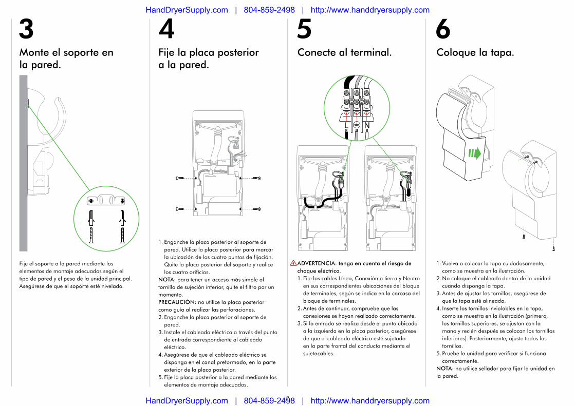
1. Enganche la placa posterior al soporte de pared. Utilice la placa posterior para marcar la ubicación de los cuatro puntos de fijación. Quite la placa posterior del soporte y realice los cuatro orificios.
NOTA: para tener un acceso más simple al tornillo de sujeción inferior, quite el filtro por un momento. PRECAUCIÓN: no utilice la placa posterior como guía al realizar las perforaciones.2. Enganche la placa posterior al soporte de
pared.3. Instale el cableado eléctrico a través del punto
de entrada correspondiente al cableado eléctrico.
4. Asegúrese de que el cableado eléctrico se disponga en el canal preformado, en la parte exterior de la placa posterior.
5. Fije la placa posterior a la pared mediante los elementos de montaje adecuados.
ADVERTENCIA: tenga en cuenta el riesgo de choque eléctrico.1. Fije los cables Línea, Conexión a tierra y Neutro
en sus correspondientes ubicaciones del bloque de terminales, según se indica en la carcasa del bloque de terminales.
2. Antes de continuar, compruebe que las conexiones se hayan realizado correctamente.
3. Si la entrada se realiza desde el punto ubicado a la izquierda en la placa posterior, asegúrese de que el cableado eléctrico esté sujetado en la parte frontal del conducto mediante el sujetacables.
Fije el soporte a la pared mediante los elementos de montaje adecuados según el tipo de pared y el peso de la unidad principal. Asegúrese de que el soporte esté nivelado.
1. Vuelva a colocar la tapa cuidadosamente, como se muestra en la ilustración.
2. No coloque el cableado dentro de la unidad cuando disponga la tapa.
3. Antes de ajustar los tornillos, asegúrese de que la tapa esté alineada.
4. Inserte los tornillos inviolables en la tapa, como se muestra en la ilustración (primero, los tornillos superiores, se ajustan con la mano y recién después se colocan los tornillos inferiores). Posteriormente, ajuste todos los tornillos.
5. Pruebe la unidad para verificar si funciona correctamente.
NOTA: no utilice sellador para fijar la unidad en la pared.
3 4 5 6Monte el soporte en la pared.
Fije la placa posterior a la pared.
Conecte al terminal. Coloque la tapa.
HandDryerSupply.com | 804-859-2498 | http://www.handdryersupply.com
HandDryerSupply.com | 804-859-2498 | http://www.handdryersupply.com

10
HandDryerSupply.com | 804-859-2498 | http://www.handdryersupply.com
HandDryerSupply.com | 804-859-2498 | http://www.handdryersupply.com

11
HandDryerSupply.com | 804-859-2498 | http://www.handdryersupply.com
HandDryerSupply.com | 804-859-2498 | http://www.handdryersupply.com

12
JN.5
5404
PN
.632
06-0
5-0
4 2
1.03
.13
The NSF logo is a registered trademark of NSF International Corporation.
NSF ProToCol P335HygIeNIC CommerCIal
HaNd dryerS
dyson Customer Care Helplinelínea directa de asistencia al cliente de dyson
www.dysonairblade.com
If you have any questions on the installation please call us toll free at 1-888-dySoN-aB (1-888-397-6622).
Si tiene alguna pregunta sobre la instalación, llámenos a este número de acceso gratuito: 1-888-dySoN-aB (1-888-397-6622).
HandDryerSupply.com | 804-859-2498 | http://www.handdryersupply.com
HandDryerSupply.com | 804-859-2498 | http://www.handdryersupply.com