Installation Guide - FCC ID · PDF fileBefore installing an RRU, you must be familiar with its...
136
RRU3953&RRU3953w Installation Guide Issue Draft A Date 2014-09-30 HUAWEI TECHNOLOGIES CO., LTD.
Transcript of Installation Guide - FCC ID · PDF fileBefore installing an RRU, you must be familiar with its...

RRU3953&RRU3953w
Installation Guide
Issue Draft A
Date 2014-09-30
HUAWEI TECHNOLOGIES CO., LTD.

Copyright © Huawei Technologies Co., Ltd. 2014. All rights reserved.
No part of this document may be reproduced or transmitted in any form or by any means without prior writtenconsent of Huawei Technologies Co., Ltd. Trademarks and Permissions
and other Huawei trademarks are trademarks of Huawei Technologies Co., Ltd.All other trademarks and trade names mentioned in this document are the property of their respective holders. NoticeThe purchased products, services and features are stipulated by the contract made between Huawei and thecustomer. All or part of the products, services and features described in this document may not be within thepurchase scope or the usage scope. Unless otherwise specified in the contract, all statements, information,and recommendations in this document are provided "AS IS" without warranties, guarantees or representationsof any kind, either express or implied.
The information in this document is subject to change without notice. Every effort has been made in thepreparation of this document to ensure accuracy of the contents, but all statements, information, andrecommendations in this document do not constitute a warranty of any kind, express or implied.
Huawei Technologies Co., Ltd.Address: Huawei Industrial Base
Bantian, LonggangShenzhen 518129People's Republic of China
Website: http://www.huawei.com
Email: [email protected]
Issue Draft A (2014-09-30) Huawei Proprietary and ConfidentialCopyright © Huawei Technologies Co., Ltd.
i

About This Document
PurposeThis document describes the process of installing a DC blade RRU3953&RRU3953w (referredto as RRU in this document).
Product VersionsThe following table lists the product versions related to this document.
Product Name Solution Version Product Version
DBS3900 l SRAN8.0 and laterversions
l GBSS15.0 and laterversions
l eRAN6.0 and laterversions
V100R008C00 and laterversions
Intended AudienceThis document is intended for:
Base station installation engineers
Organization1 Changes in RRU3953&RRU3953w Installation Guide
This section describes the changes in the RRU3953&RRU3953w Installation Guide.
2 Installation Preparations
This chapter describes the reference documents, tools, and instruments that must be ready beforethe installation. In addition, it specifies the skills and prerequisites that installation engineersmust have.
3 Information About the Installation
RRU3953&RRU3953wInstallation Guide About This Document
Issue Draft A (2014-09-30) Huawei Proprietary and ConfidentialCopyright © Huawei Technologies Co., Ltd.
ii

Before installing an RRU, you must be familiar with its exterior, ports, indicators, installationoptions and installation clearance requirements.
4 Unpacking the Equipment
This chapter describes how to unpack and check the delivered equipment to ensure that all thematerials are included and intact.
5 Installation Process
The installation process involves installing an RRU and RRU cables, checking the RRUhardware installation, and powering on an RRU.
6 (Optional) Installing the Plastic Shells of the RRU
This section describes the procedure for installing the plastic shells of the RRU.
7 Hoisting an RRU and Related Cables onto a Tower
This section describes the procedure for hoisting an RRU and related cables onto a tower andthe precautions that must be taken.
8 Installing the RRU
This chapter describes the procedure for installing the RRU. The procedure for installing theRRU varies depending on installation options.
9 Installing RRU Cables
This chapter describes the procedure for installing RRU cables.
10 Checking the RRU Hardware Installation
After an RRU is installed, check the hardware installation.
11 Powering On an RRU
After all the devices are installed, check the power-on status of an RRU.
12 Appendix
This section describes the procedure for adding an easy power receptacle (pressfit type)connector.
ConventionsSymbol Conventions
The symbols that may be found in this document are defined as follows.
Symbol Description
Indicates an imminently hazardous situation which, if notavoided, will result in death or serious injury.
Indicates a potentially hazardous situation which, if notavoided, could result in death or serious injury.
RRU3953&RRU3953wInstallation Guide About This Document
Issue Draft A (2014-09-30) Huawei Proprietary and ConfidentialCopyright © Huawei Technologies Co., Ltd.
iii

Symbol Description
Indicates a potentially hazardous situation which, if notavoided, may result in minor or moderate injury.
Indicates a potentially hazardous situation which, if notavoided, could result in equipment damage, data loss,performance deterioration, or unanticipated results.NOTICE is used to address practices not related to personalinjury.
Calls attention to important information, best practices andtips.NOTE is used to address information not related to personalinjury, equipment damage, and environment deterioration.
General Conventions
The general conventions that may be found in this document are defined as follows.
Convention Description
Times New Roman Normal paragraphs are in Times New Roman.
Boldface Names of files, directories, folders, and users are inboldface. For example, log in as user root.
Italic Book titles are in italics.
Courier New Examples of information displayed on the screen are inCourier New.
Command Conventions
The command conventions that may be found in this document are defined as follows.
Convention Description
Boldface The keywords of a command line are in boldface.
Italic Command arguments are in italics.
[ ] Items (keywords or arguments) in brackets [ ] are optional.
{ x | y | ... } Optional items are grouped in braces and separated byvertical bars. One item is selected.
[ x | y | ... ] Optional items are grouped in brackets and separated byvertical bars. One item is selected or no item is selected.
RRU3953&RRU3953wInstallation Guide About This Document
Issue Draft A (2014-09-30) Huawei Proprietary and ConfidentialCopyright © Huawei Technologies Co., Ltd.
iv

Convention Description
{ x | y | ... }* Optional items are grouped in braces and separated byvertical bars. A minimum of one item or a maximum of allitems can be selected.
[ x | y | ... ]* Optional items are grouped in brackets and separated byvertical bars. Several items or no item can be selected.
GUI Conventions
The GUI conventions that may be found in this document are defined as follows.
Convention Description
Boldface Buttons, menus, parameters, tabs, window, and dialog titlesare in boldface. For example, click OK.
> Multi-level menus are in boldface and separated by the ">"signs. For example, choose File > Create > Folder.
Keyboard Operations
The keyboard operations that may be found in this document are defined as follows.
Format Description
Key Press the key. For example, press Enter and press Tab.
Key 1+Key 2 Press the keys concurrently. For example, pressing Ctrl+Alt+A means the three keys should be pressed concurrently.
Key 1, Key 2 Press the keys in turn. For example, pressing Alt, A meansthe two keys should be pressed in turn.
Mouse Operations
The mouse operations that may be found in this document are defined as follows.
Action Description
Click Select and release the primary mouse button without movingthe pointer.
Double-click Press the primary mouse button twice continuously andquickly without moving the pointer.
RRU3953&RRU3953wInstallation Guide About This Document
Issue Draft A (2014-09-30) Huawei Proprietary and ConfidentialCopyright © Huawei Technologies Co., Ltd.
v

Action Description
Drag Press and hold the primary mouse button and move thepointer to a certain position.
RRU3953&RRU3953wInstallation Guide About This Document
Issue Draft A (2014-09-30) Huawei Proprietary and ConfidentialCopyright © Huawei Technologies Co., Ltd.
vi
Contents
About This Document.....................................................................................................................ii
1 Changes in RRU3953&RRU3953w Installation Guide..........................................................1
2 Installation Preparations..............................................................................................................22.1 Reference Documents.....................................................................................................................................................32.2 Tools and Instruments....................................................................................................................................................32.3 Skills and Requirements for Onsite Personnel...............................................................................................................5
3 Information About the Installation...........................................................................................63.1 RRU Exterior..................................................................................................................................................................73.2 RRU Ports.......................................................................................................................................................................83.3 RRU Indicators.............................................................................................................................................................103.4 Installation Scenarios....................................................................................................................................................123.5 Installation Clearance Requirements of an RRU..........................................................................................................233.5.1 Clearance for a Single RRU......................................................................................................................................233.5.2 Clearance for Three or More RRUs...........................................................................................................................283.5.3 Installation Spacing Between RRUs..........................................................................................................................31
4 Unpacking the Equipment.........................................................................................................34
5 Installation Process.....................................................................................................................36
6 (Optional) Installing the Plastic Shells of the RRU..............................................................37
7 Hoisting an RRU and Related Cables onto a Tower............................................................407.1 Hoisting an RRU onto a Tower....................................................................................................................................417.2 Hoisting Fiber Optic Cables onto a Tower...................................................................................................................447.3 Hoisting Power Cables onto a Tower...........................................................................................................................47
8 Installing the RRU.......................................................................................................................508.1 Mounting Kits for an RRU...........................................................................................................................................518.2 Installing the RRU on a Pole........................................................................................................................................528.2.1 Installing a Single RRU.............................................................................................................................................528.2.2 Installing Two RRUs.................................................................................................................................................558.2.3 Installing Three or More RRUs.................................................................................................................................618.3 Installing an RRU on U-steel .......................................................................................................................................66
RRU3953&RRU3953wInstallation Guide Contents
Issue Draft A (2014-09-30) Huawei Proprietary and ConfidentialCopyright © Huawei Technologies Co., Ltd.
vii
8.4 Installing an RRU on Angle Steel................................................................................................................................718.5 Installing an RRU on a Wall.........................................................................................................................................768.6 Installing an RRU on an IFS06.....................................................................................................................................82
9 Installing RRU Cables................................................................................................................899.1 Cabling Requirements..................................................................................................................................................919.2 RRU Cable Connections...............................................................................................................................................979.3 Installing RRU Cables................................................................................................................................................1019.4 RRU Cables................................................................................................................................................................1029.5 Installing an RRU PGND Cable.................................................................................................................................1039.6 Installing an RRU RF Jumper....................................................................................................................................1059.7 Installing an RRU AISG Multi-Wire Cable and AISG Extension Cable...................................................................1089.8 Installing an RRU Alarm Cable..................................................................................................................................1109.9 Opening the Cover Plate of an RRU Cabling Cavity.................................................................................................1129.10 Installing a CPRI Optical Cable...............................................................................................................................1139.11 Installing an RRU Power Cable................................................................................................................................1159.12 Closing the Cover Plate of an RRU Cabling Cavity................................................................................................118
10 Checking the RRU Hardware Installation..........................................................................120
11 Powering On an RRU.............................................................................................................121
12 Appendix...................................................................................................................................12312.1 Adding a Tool-Less Female Connector (Pressfit Type) to the RRU Power Cable on the RRU Side......................124
RRU3953&RRU3953wInstallation Guide Contents
Issue Draft A (2014-09-30) Huawei Proprietary and ConfidentialCopyright © Huawei Technologies Co., Ltd.
viii

1 Changes in RRU3953&RRU3953wInstallation Guide
This section describes the changes in the RRU3953&RRU3953w Installation Guide.
Draft A (2014-09-30)This is a draft.
RRU3953&RRU3953wInstallation Guide 1 Changes in RRU3953&RRU3953w Installation Guide
Issue Draft A (2014-09-30) Huawei Proprietary and ConfidentialCopyright © Huawei Technologies Co., Ltd.
1

2 Installation Preparations
About This Chapter
This chapter describes the reference documents, tools, and instruments that must be ready beforethe installation. In addition, it specifies the skills and prerequisites that installation engineersmust have.
2.1 Reference DocumentsBefore the installation, you must be familiar with reference documents.
2.2 Tools and InstrumentsYou must prepare the following tools and instruments before the installation.
2.3 Skills and Requirements for Onsite PersonnelOnsite personnel must be qualified and trained. Before performing any operation, onsitepersonnel must be familiar with correct operation methods and safety precautions.
RRU3953&RRU3953wInstallation Guide 2 Installation Preparations
Issue Draft A (2014-09-30) Huawei Proprietary and ConfidentialCopyright © Huawei Technologies Co., Ltd.
2

2.1 Reference DocumentsBefore the installation, you must be familiar with reference documents.
The following reference documents are required during RRU installation:l RRU3953&RRU3953w Hardware Descriptionl DBS3900 Installation Guidel OCB User Guidel OCB-01M User Guide
2.2 Tools and InstrumentsYou must prepare the following tools and instruments before the installation.
Hammer drill (a φ12 bit) ESD gloves Vacuum cleaner
Heat gun Phillips screwdriver (M3 toM6)
Flat-head screwdriver (M3 toM6)
Rubber mallet COAX crimping tool Wire stripper
RRU3953&RRU3953wInstallation Guide 2 Installation Preparations
Issue Draft A (2014-09-30) Huawei Proprietary and ConfidentialCopyright © Huawei Technologies Co., Ltd.
3

Utility knife Cable cutter Adjustable wrench (size ≥ 32mm [1.26 in.])
Torque wrench
Size: 16 mm (0.63 in.) and 32mm (1.26 in.)Combination wrench
Size: 16 mm (0.63 in.) and 32mm (1.26 in.)
Level Torque screwdriver
5 mm
5 mm
(M3 to M6)
(M3 to M6)
Torque socket
Multimeter Marker (diameter ≤ 10 mm[0.39 in.])
Measuring tape
Inner hexagon wrench
5 mm
Fixed pulley Lifting sling
Hydraulic pliers - -
RRU3953&RRU3953wInstallation Guide 2 Installation Preparations
Issue Draft A (2014-09-30) Huawei Proprietary and ConfidentialCopyright © Huawei Technologies Co., Ltd.
4

2.3 Skills and Requirements for Onsite PersonnelOnsite personnel must be qualified and trained. Before performing any operation, onsitepersonnel must be familiar with correct operation methods and safety precautions.
Before the installation, pay attention to the following items:
l The customer's technical engineers must be trained by Huawei and be familiar with theproper installation and operation methods.
l The number of onsite personnel depends on the engineering schedule and installationenvironment. Generally, only three to five onsite personnel are necessary.
RRU3953&RRU3953wInstallation Guide 2 Installation Preparations
Issue Draft A (2014-09-30) Huawei Proprietary and ConfidentialCopyright © Huawei Technologies Co., Ltd.
5

3 Information About the Installation
About This Chapter
Before installing an RRU, you must be familiar with its exterior, ports, indicators, installationoptions and installation clearance requirements.
3.1 RRU ExteriorThis section describes the exterior and dimensions of an RRU.
3.2 RRU PortsThis section describes ports on the RRU panels. An RRU has a bottom panel, cabling cavitypanel, and indicator panel.
3.3 RRU IndicatorsThis section describes six indicators on an RRU. They indicate the running status of the RRU.
3.4 Installation ScenariosAn RRU can be installed on a pole, U-steel, angle steel, wall, or IFS06. Installation scenariosmust meet heat-dissipation and waterproofing requirements of the RRU.
3.5 Installation Clearance Requirements of an RRUThis section describes the requirements for the installation clearance of a single RRU andmultiple RRUs and the requirements for the installation spacing between RRUs.
RRU3953&RRU3953wInstallation Guide 3 Information About the Installation
Issue Draft A (2014-09-30) Huawei Proprietary and ConfidentialCopyright © Huawei Technologies Co., Ltd.
6

3.1 RRU ExteriorThis section describes the exterior and dimensions of an RRU.
Figure 3-1 shows the exterior of an RRU.
Figure 3-1 RRU exterior
Figure 3-2 shows RRU dimensions.
Figure 3-2 RRU dimensions
You can obtain the RRU frequency band and power supply information from the configurationlabel on the cover plate and obtain the RRU name from the nameplate on the side of RRU thataccommodates the conversion bracket. Figure 3-3 shows the positions of the configuration labeland nameplate on the RRU.
RRU3953&RRU3953wInstallation Guide 3 Information About the Installation
Issue Draft A (2014-09-30) Huawei Proprietary and ConfidentialCopyright © Huawei Technologies Co., Ltd.
7

NOTE
The actual label and nameplate may differ from what is shown in the figure.
Figure 3-3 Positions of the label and nameplate
(1) Configuration label (2) Nameplate (3) Frequency band
(4) Power supply module (5) Module name -
3.2 RRU PortsThis section describes ports on the RRU panels. An RRU has a bottom panel, cabling cavitypanel, and indicator panel.
Figure 3-4 shows the ports on the RRU panels.
RRU3953&RRU3953wInstallation Guide 3 Information About the Installation
Issue Draft A (2014-09-30) Huawei Proprietary and ConfidentialCopyright © Huawei Technologies Co., Ltd.
8

Figure 3-4 Ports on the RRU panels
Table 3-1 describes ports and indicators on the RRU panels.
Table 3-1 Ports and indicators on the RRU panels
Item Silkscreen Remarks
(1) Ports in the cablingcavity
RTN(+) Power supply socket, for details about RRUpower cable experience and specifications,see RRU Power Cable.NEG(-)
CPRI0 Optical/electrical port 0, connected to theBBU
RRU3953&RRU3953wInstallation Guide 3 Information About the Installation
Issue Draft A (2014-09-30) Huawei Proprietary and ConfidentialCopyright © Huawei Technologies Co., Ltd.
9

Item Silkscreen Remarks
CPRI1 Optical/electrical port 1, connected to theBBU
(2) Bottom ports ANT_TX/RXA TX/RX port A, supporting RET signaltransmission
ANT_TX/RXB TX/RX port B, supporting RET signaltransmission
ANT_RXC TX/RX port C
ANT_RXD TX/RX port D
EXT_ALM Alarm monitoring port used for monitoringone RS485 signal and two dry contact signals
RET Communication port for the RET antenna,supporting RET signal transmission
(3) Indicator RUN For details, see 3.3 RRU Indicators.
ALM
ACT
VSWR
CPRI0
CPRI1
NOTE
l The port for transmitting RET signals is determined by the software.
l Connect the CPRI0 port to the BBU by default in the single-mode scenario.
3.3 RRU IndicatorsThis section describes six indicators on an RRU. They indicate the running status of the RRU.
For detailed positions of RRU indicators, see 3.2 RRU Ports.
Table 3-2 describes RRU indicators.
Table 3-2 RRU Indicators
Indicator Color Status Meaning
RUN Green Steady on The power input is available, but the board isfaulty.
RRU3953&RRU3953wInstallation Guide 3 Information About the Installation
Issue Draft A (2014-09-30) Huawei Proprietary and ConfidentialCopyright © Huawei Technologies Co., Ltd.
10

Indicator Color Status Meaning
Steady off No power input is available or the board isfaulty.
Blinking (on for1s and off for 1s)
The board is running properly.
Blinking (on for0.125s and off for0.125s)
The board software is being loaded or theboard is not working.
ALM Red Steady on Alarms are generated, and the module mustbe replaced.
Blinking (on for1s and off for 1s)
Alarms are generated. The alarms may becaused by faults on the related board or ports.Therefore, you need to locate the fault beforedeciding whether to replace the module.
Steady off No alarms are generated.
ACT Green Steady on The board is working properly when TXchannels are enabled or software is beingloaded to a board that is not started.
Blinking (on for1s and off for 1s)
The board is running with TX channelsdisabled.
VSWR Red Steady off No voltage standing wave ratio (VSWR)alarm is generated.
Blinking (on for1s and off for 1s)
VSWR alarms are generated on theANT_TX/RXB port.
Steady on VSWR alarms are generated on theANT_TX/RXA port.
Blinking (on for0.125s and off for0.125s)
VSWR alarms are generated on theANT_TX/RXA and ANT_TX/RXB ports.
CPRI0 Red andgreen
Steady green The CPRI link is running properly.
Steady red An optical module fails to receive or transmitsignals possibly because the optical moduleis faulty or the optical fiber is broken.
Blinking red (onfor 1s and off for1s)
The CPRI link is out of lock because of faultson the mutual lock of dual-mode clocksources or mismatched data rates on CPRIports.
Steady off The optical module cannot be detected or ispowered off.
RRU3953&RRU3953wInstallation Guide 3 Information About the Installation
Issue Draft A (2014-09-30) Huawei Proprietary and ConfidentialCopyright © Huawei Technologies Co., Ltd.
11
Indicator Color Status Meaning
CPRI1 Red andgreen
Steady green The CPRI link is running properly.
Steady red An optical module fails to receive or transmitsignals possibly because the optical moduleis faulty or the optical fiber is broken.
Blinking red (onfor 1s and off for1s)
The CPRI link is out of lock because of faultson the mutual lock of dual-mode clocksources or mismatched data rates on CPRIports.
Steady off The optical module cannot be detected or ispowered off.
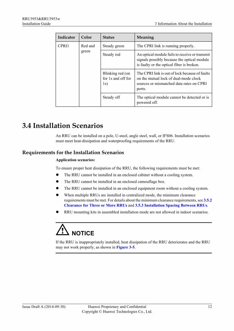
3.4 Installation ScenariosAn RRU can be installed on a pole, U-steel, angle steel, wall, or IFS06. Installation scenariosmust meet heat-dissipation and waterproofing requirements of the RRU.
Requirements for the Installation ScenariosApplication scenarios:
To ensure proper heat dissipation of the RRU, the following requirements must be met:l The RRU cannot be installed in an enclosed cabinet without a cooling system.l The RRU cannot be installed in an enclosed camouflage box.l The RRU cannot be installed in an enclosed equipment room without a cooling system.l When multiple RRUs are installed in centralized mode, the minimum clearance
requirements must be met. For details about the minimum clearance requirements, see 3.5.2Clearance for Three or More RRUs and 3.5.3 Installation Spacing Between RRUs.
l RRU mounting kits in assembled installation mode are not allowed in indoor scenarios.
NOTICEIf the RRU is inappropriately installed, heat dissipation of the RRU deteriorates and the RRUmay not work properly, as shown in Figure 3-5.
RRU3953&RRU3953wInstallation Guide 3 Information About the Installation
Issue Draft A (2014-09-30) Huawei Proprietary and ConfidentialCopyright © Huawei Technologies Co., Ltd.
12

Figure 3-5 inappropriately installed RRU
Correct installation methods:l The installation supports' specifications described in this document are only based on the
exterior and dimensions of the mounting kits. Before installing equipment, assess thestrength and reliability of the installation support to determine whether it can bear the weightof the equipment.
l If an AC RRU consists of a 18 L blade RRU and an OPM15M, this AC RRU cannot beinstalled in side-mounted mode.
l To ensure the heat dissipation of the RRU and waterproofing of the ports at the bottom ofthe RRU, the vertical deviation angle of an RRU must be less than or equal to 10 degrees,as shown Figure 3-6.
l On a tower, an RRU can be installed on a pole, angle steel, or U-steel. The side-mountedinstallation mode (one side instead of the rear of an RRU is mounted on the support) isrecommended for RRUs on the main pole secured on a tower. This installation mode allowsmultiple RRUs to be installed next to each other at the same level on a pole. When thehorizontal distance between the main and auxiliary poles on a tower is equal to or greaterthan 810 mm (23.62 in.), the side-mounted mode is recommended for installing RRUs onthe auxiliary pole to meet the minimum clearance requirements. Otherwise, the standardmode is recommended for installing RRUs on the auxiliary pole.
RRU3953&RRU3953wInstallation Guide 3 Information About the Installation
Issue Draft A (2014-09-30) Huawei Proprietary and ConfidentialCopyright © Huawei Technologies Co., Ltd.
13

Figure 3-6 Requirements for the vertical deviation angle of an RRU
(1) RRU (2) Installation support (pole, U-steel, angle steel, or wall)
Installing an RRU on a PoleFigure 3-7 shows the diameter of a pole for installing an RRU.
Figure 3-7 Diameter of a pole
NOTICEl The diameter of a pole for installing an RRU ranges from 60 mm (2.36 in.) to 114 mm (4.49
in.). The recommended diameter is 80 mm (3.15 in.).l When the diameter of a pole ranges from 60 mm (2.36 in.) to 76 mm (2.99 in.), a maximum
of three RRUs can be installed on the pole and the side-mounted installation is recommended.l Only a pole whose diameter ranges from 76 mm (2.99 in.) to 114 mm (4.49 in.) supports
more than three RRUs.l The recommended thickness of the pole wall is 3.5 mm (0.14 in.) or above.
Figure 3-8 shows a single RRU installed on a pole.
RRU3953&RRU3953wInstallation Guide 3 Information About the Installation
Issue Draft A (2014-09-30) Huawei Proprietary and ConfidentialCopyright © Huawei Technologies Co., Ltd.
14

Figure 3-8 A single RRU installed on a pole
Figure 3-9 shows two RRUs installed on a pole.
Figure 3-9 Two RRUs installed on a pole
Figure 3-10, Figure 3-11, and Figure 3-12 show multiple RRUs installed on a pole.
RRU3953&RRU3953wInstallation Guide 3 Information About the Installation
Issue Draft A (2014-09-30) Huawei Proprietary and ConfidentialCopyright © Huawei Technologies Co., Ltd.
15
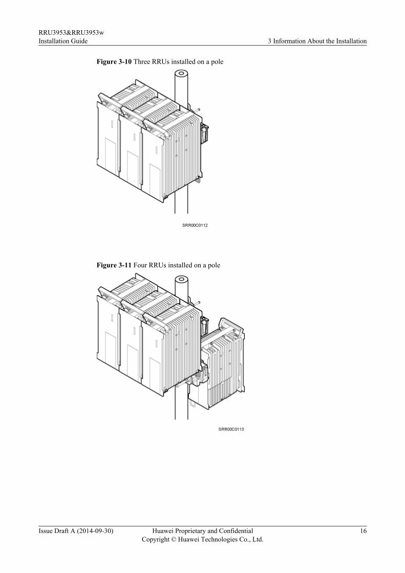
Figure 3-10 Three RRUs installed on a pole
Figure 3-11 Four RRUs installed on a pole
RRU3953&RRU3953wInstallation Guide 3 Information About the Installation
Issue Draft A (2014-09-30) Huawei Proprietary and ConfidentialCopyright © Huawei Technologies Co., Ltd.
16

Figure 3-12 Six RRUs installed on a pole
Installing an RRU on U-SteelFigure 3-13 shows U-steel specifications.
Figure 3-13 U-steel specifications
NOTICEU-steel only supports the standard or reverse installation of a single RRU.
Figure 3-14 shows an RRU installed on U-steel.
RRU3953&RRU3953wInstallation Guide 3 Information About the Installation
Issue Draft A (2014-09-30) Huawei Proprietary and ConfidentialCopyright © Huawei Technologies Co., Ltd.
17

Figure 3-14 RRU installed on U-steel
Installing an RRU on Angle Steel
Figure 3-15 shows angle steel specifications.
Figure 3-15 Angle steel specifications
NOTICEAngle steel only supports the standard or reverse installation of a single RRU.
Figure 3-16 shows an RRU installed on angle steel.
RRU3953&RRU3953wInstallation Guide 3 Information About the Installation
Issue Draft A (2014-09-30) Huawei Proprietary and ConfidentialCopyright © Huawei Technologies Co., Ltd.
18

Figure 3-16 RRU installed on angle steel
Installing an RRU on a WallThe wall for installing RRUs must meet the following requirements:l For each RRU, the wall must be able to bear a weight four times heavier than the RRU's
weight and the bolts' pulling force of 1.25 kN (281.25 lbf) vertical to the wall.l Expansion bolts must be tightened to 30 N•m to ensure that the bolts work properly and
the wall remains intact.
NOTICEl The standard installation is recommended for RRUs installed on a wall.l When RRUs are installed on a wall in side-mounted mode, do not combine mounting brackets
for multiple RRUs, as shown in Figure 3-17.
Figure 3-17 Correct installation of mounting brackets for multiple RRUs installed on a wall inside-mounted mode
RRU3953&RRU3953wInstallation Guide 3 Information About the Installation
Issue Draft A (2014-09-30) Huawei Proprietary and ConfidentialCopyright © Huawei Technologies Co., Ltd.
19

Figure 3-18 shows an RRU installed on a wall.
Figure 3-18 RRU installed on a wall
Installing an RRU on an IFS06
l The upper and lower adjustable beams on an IFS06 can be moved up and down to fit forheights of RRUs.
l The IFS06 supports at least three RRUs when the ambient temperature is higher than orequal to the lowest operating temperature of the RRUs and at least 5°C (41°F) lower thanthe highest operating temperature of the RRUs. The IFS06 supports a maximum of sixRRUs when the ambient temperature is higher than or equal to the lowest operatingtemperature of the RRUs and at least 10°C (50°F) lower than the highest operatingtemperature of the RRUs.
NOTE
For details about the operating temperature of the RRUs, see section "Technical Specifications ofRRUs" in 3900 Series Base Station Technical Description.
NOTICEThe mounting brackets for multiple RRUs cannot be combined when the RRUs are installed onan IFS06, as shown in Figure 3-19.
RRU3953&RRU3953wInstallation Guide 3 Information About the Installation
Issue Draft A (2014-09-30) Huawei Proprietary and ConfidentialCopyright © Huawei Technologies Co., Ltd.
20

Figure 3-19 Correct installation of mounting brackets for RRUs installed on an IFS06
Figure 3-20 and Figure 3-21 show RRUs installed on an IFS06.
RRU3953&RRU3953wInstallation Guide 3 Information About the Installation
Issue Draft A (2014-09-30) Huawei Proprietary and ConfidentialCopyright © Huawei Technologies Co., Ltd.
21
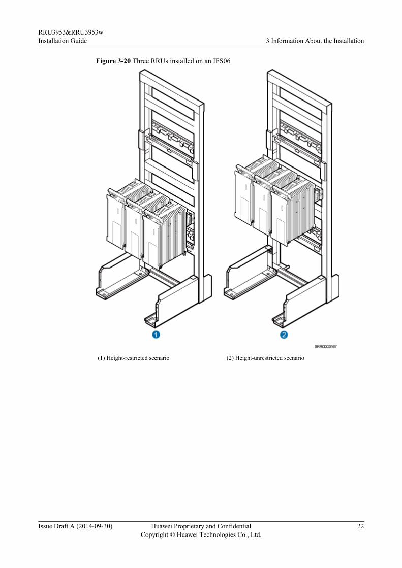
Figure 3-20 Three RRUs installed on an IFS06
(1) Height-restricted scenario (2) Height-unrestricted scenario
RRU3953&RRU3953wInstallation Guide 3 Information About the Installation
Issue Draft A (2014-09-30) Huawei Proprietary and ConfidentialCopyright © Huawei Technologies Co., Ltd.
22

Figure 3-21 Six RRUs installed on an IFS06
(1) Height-restricted scenario (2) Height-unrestricted scenario
3.5 Installation Clearance Requirements of an RRUThis section describes the requirements for the installation clearance of a single RRU andmultiple RRUs and the requirements for the installation spacing between RRUs.
3.5.1 Clearance for a Single RRUThis section describes the recommended and minimum clearances for a single RRU.
RRU3953&RRU3953wInstallation Guide 3 Information About the Installation
Issue Draft A (2014-09-30) Huawei Proprietary and ConfidentialCopyright © Huawei Technologies Co., Ltd.
23

NOTICEIf an RRU is installed on the bitumen ground, the RRU must be at least 500 mm (700 mm ormore as recommended) away from the bitumen ground. The following describes the spacerequirements for installing a single RRU on the non-bitumen ground.
NOTE
l The recommended clearances ensure normal running and provide appropriate space for operation andmaintenance (O&M). If the installation space is sufficient, leave the recommended clearances afterinstalling the equipment.
l The minimum clearance ensures normal running and heat dissipation, but O&M activities such aschecking indicator status and opening the cabling cavity cannot be properly conducted. If theinstallation space is restricted, leave the minimum clearance after installing the equipment.
Clearance for a Single RRU in Side-Mounted ModeFigure 3-22 shows the clearance for a single RRU in side-mounted mode.
RRU3953&RRU3953wInstallation Guide 3 Information About the Installation
Issue Draft A (2014-09-30) Huawei Proprietary and ConfidentialCopyright © Huawei Technologies Co., Ltd.
24

Figure 3-22 Clearance for a single RRU in side-mounted mode
Clearance for a Single RRU in Standard or Reverse ModeFigure 3-23 shows the clearance for a single RRU in standard or reverse mode.
RRU3953&RRU3953wInstallation Guide 3 Information About the Installation
Issue Draft A (2014-09-30) Huawei Proprietary and ConfidentialCopyright © Huawei Technologies Co., Ltd.
25

Figure 3-23 Clearance for a single RRU in standard or reverse mode
Clearance for a Single Tower-Mounted RRUFigure 3-24 and Figure 3-25 show the minimum clearances for a single RRU in side-mountedmode and standard or reverse mode on a tower.
RRU3953&RRU3953wInstallation Guide 3 Information About the Installation
Issue Draft A (2014-09-30) Huawei Proprietary and ConfidentialCopyright © Huawei Technologies Co., Ltd.
26

Figure 3-24 Minimum clearance for a single RRU in side-mounted mode on a tower
Figure 3-25 Minimum clearance for a single RRU in standard or reverse mode on a tower
RRU3953&RRU3953wInstallation Guide 3 Information About the Installation
Issue Draft A (2014-09-30) Huawei Proprietary and ConfidentialCopyright © Huawei Technologies Co., Ltd.
27

3.5.2 Clearance for Three or More RRUsThis section describes the recommended and minimum clearances for three or more RRUs.
NOTICEIf an RRU is installed on the bitumen ground, the RRU must be at least 500 mm (700 mm ormore as recommended) away from the bitumen ground. The following describes the spacerequirements for installing multiple RRUs on the non-bitumen ground.
NOTE
l The recommended clearances ensure normal running and provide appropriate space for operation andmaintenance (O&M). If the installation space is sufficient, leave the recommended clearances afterinstalling the equipment.
l The minimum clearance ensures normal running and heat dissipation, but O&M activities such aschecking indicator status and opening the cabling cavity cannot be properly conducted. If theinstallation space is restricted, leave the minimum clearance after installing the equipment.
Recommended Clearances for Three or More RRUs Installed in Centralized ModeFigure 3-26 shows the recommended clearances for three or more RRUs installed in centralizedmode.
Figure 3-26 Recommended clearances for three or more RRUs installed in centralized mode
RRU3953&RRU3953wInstallation Guide 3 Information About the Installation
Issue Draft A (2014-09-30) Huawei Proprietary and ConfidentialCopyright © Huawei Technologies Co., Ltd.
28

Minimum Clearances for Three or More RRUs Installed in Centralized ModeFigure 3-27 shows the minimum clearances for three or more RRUs installed in centralizedmode.
Figure 3-27 Minimum clearances for three or more RRUs installed in centralized mode
Recommended Clearances for Three or More RRUs Installed in Standard Mode ona Wall
Figure 3-28 shows the recommended clearances for three or more RRUs installed in standardmode on a wall.
RRU3953&RRU3953wInstallation Guide 3 Information About the Installation
Issue Draft A (2014-09-30) Huawei Proprietary and ConfidentialCopyright © Huawei Technologies Co., Ltd.
29

Figure 3-28 Recommended clearances for three or more RRUs installed in standard mode on awall
Minimum Clearances for Three or More RRUs Installed in Standard Mode on aWall
Figure 3-29 shows the minimum clearances for three or more RRUs installed in standard modeon a wall.
Figure 3-29 Minimum clearances for three or more RRUs installed in standard mode on a wall
RRU3953&RRU3953wInstallation Guide 3 Information About the Installation
Issue Draft A (2014-09-30) Huawei Proprietary and ConfidentialCopyright © Huawei Technologies Co., Ltd.
30

Recommended Clearances for Three or More RRUs Installed in Side-MountedMode on a Wall
Figure 3-30 shows the recommended clearances for three or more RRUs installed in side-mounted mode on a wall.
Figure 3-30 Recommended clearances for three or more RRUs installed in side-mounted modeon a wall
3.5.3 Installation Spacing Between RRUsThis section describes the horizontal and vertical spacing between RRUs.
Recommended Horizontal Spacing Between RRUsFigure 3-31 shows the recommended horizontal spacing between RRUs.
Figure 3-31 Recommended horizontal spacing between RRUs
RRU3953&RRU3953wInstallation Guide 3 Information About the Installation
Issue Draft A (2014-09-30) Huawei Proprietary and ConfidentialCopyright © Huawei Technologies Co., Ltd.
31

Minimum Horizontal Spacing Between RRUsFigure 3-32 shows the minimum horizontal spacing between RRUs.
Figure 3-32 Minimum horizontal spacing between RRUs
Recommended Vertical Spacing Between RRUsFigure 3-33 shows the recommended vertical spacing between RRUs.
Figure 3-33 Recommended vertical spacing between RRUs
RRU3953&RRU3953wInstallation Guide 3 Information About the Installation
Issue Draft A (2014-09-30) Huawei Proprietary and ConfidentialCopyright © Huawei Technologies Co., Ltd.
32

Minimum Vertical Spacing Between RRUsFigure 3-34 shows the minimum vertical spacing between RRUs.
Figure 3-34 Minimum vertical spacing between RRUs
RRU3953&RRU3953wInstallation Guide 3 Information About the Installation
Issue Draft A (2014-09-30) Huawei Proprietary and ConfidentialCopyright © Huawei Technologies Co., Ltd.
33

4 Unpacking the Equipment
This chapter describes how to unpack and check the delivered equipment to ensure that all thematerials are included and intact.
ContextNOTE
When transporting, moving, or installing the equipment, components, or parts, you must:
l Prevent them from colliding with doors, walls, shelves, or other objects.
l Wear clean gloves, and avoid touching the equipment, components, or parts with bare hands, sweat-soaked gloves, or dirty gloves.
NOTICEl After a cabinet or an BBU is unpacked, it must be powered on within 7 days.
l After an RRU is unpacked, it must be powered on within 24 hours.
Procedure
Step 1 Check the total number of articles in each case according to the packing list.
If ... Then ...
The total number tallies with the packinglist
Go to Step 2.
The total number does not tally with thepacking list
Find out the cause and report any missingarticles to the local Huawei office.
Step 2 Check the exterior of the packing case.
RRU3953&RRU3953wInstallation Guide 4 Unpacking the Equipment
Issue Draft A (2014-09-30) Huawei Proprietary and ConfidentialCopyright © Huawei Technologies Co., Ltd.
34

If ... Then ...
The outer packing is intact Go to Step 3.
The outer packing is severely damaged orsoaked
Find out the cause and report it to the localHuawei office.
Step 3 Check the type and quantity of the equipment in the cases according to the packing list.
If ... Then ...
Types and quantity of the article tally withthose on the packing list
Sign the Packing List with the customer.
Either shipment shortage, wrong shipmentor damaged articles.
Report to the local Huawei office.
CAUTIONl To protect the equipment and prevent damage to the equipment, you are advised to keep the
unpacked equipment and packing materials indoors, take photos of the stocking environment,packing case or carton, packing materials, and any rusted or eroded equipment, and then filethe photos.
l Verify that the insulation layers of all RRU cables are intact. If the insulation layers aredamaged or broken, water will penetrate into the cables, which may cause damages to RRUsor human injury.
----End
RRU3953&RRU3953wInstallation Guide 4 Unpacking the Equipment
Issue Draft A (2014-09-30) Huawei Proprietary and ConfidentialCopyright © Huawei Technologies Co., Ltd.
35

5 Installation Process
The installation process involves installing an RRU and RRU cables, checking the RRUhardware installation, and powering on an RRU.
Figure 5-1 shows the installation process.
Figure 5-1 Process of installing an RRU
RRU3953&RRU3953wInstallation Guide 5 Installation Process
Issue Draft A (2014-09-30) Huawei Proprietary and ConfidentialCopyright © Huawei Technologies Co., Ltd.
36

6 (Optional) Installing the Plastic Shells of theRRU
This section describes the procedure for installing the plastic shells of the RRU.
Context
An RRU is equipped with a plastic shell only when necessary.
Procedure
Step 1 Use an M6 Phillips screwdriver to loosen the two screws on the metal sheet of the RRU andremove the metal sheet, as shown in Figure 6-1.
Figure 6-1 Removing the metal sheet
(1) Screw (2) Metal sheet
RRU3953&RRU3953wInstallation Guide 6 (Optional) Installing the Plastic Shells of the RRU
Issue Draft A (2014-09-30) Huawei Proprietary and ConfidentialCopyright © Huawei Technologies Co., Ltd.
37

Step 2 Install a buckle on each side at the bottom of the RRU, and use an M4 torque wrench to tightenthe screws on the buckles to 1.4 N·m (12.39 lbf·in.), as shown in Figure 6-2.
Figure 6-2 Installing buckles at the bottom
(1) Buckle (2) Screw
Step 3 Use four hex screws to secure the plastic shells onto the RRU and use an M6 hex key wrenchto tighten the screws to 2.8 N·m (24.78 lbf·in.), as shown in Figure 6-3.
RRU3953&RRU3953wInstallation Guide 6 (Optional) Installing the Plastic Shells of the RRU
Issue Draft A (2014-09-30) Huawei Proprietary and ConfidentialCopyright © Huawei Technologies Co., Ltd.
38

Figure 6-3 Installing the plastic shells of the RRU
----End
RRU3953&RRU3953wInstallation Guide 6 (Optional) Installing the Plastic Shells of the RRU
Issue Draft A (2014-09-30) Huawei Proprietary and ConfidentialCopyright © Huawei Technologies Co., Ltd.
39

7 Hoisting an RRU and Related Cables onto aTower
About This Chapter
This section describes the procedure for hoisting an RRU and related cables onto a tower andthe precautions that must be taken.
7.1 Hoisting an RRU onto a TowerThis section describes the procedures and precautions for hoisting an RRU and its mounting kitsonto a tower. In tower-mounted scenarios, the RRU can be installed on a pole, U-steel, or anglesteel.
7.2 Hoisting Fiber Optic Cables onto a TowerThis section describes the procedure for hoisting fiber optic cables onto a tower and theprecautions that must be taken.
7.3 Hoisting Power Cables onto a TowerThis section describes the procedure for hoisting power cables onto a tower and the precautionsthat must be taken.
RRU3953&RRU3953wInstallation Guide 7 Hoisting an RRU and Related Cables onto a Tower
Issue Draft A (2014-09-30) Huawei Proprietary and ConfidentialCopyright © Huawei Technologies Co., Ltd.
40

7.1 Hoisting an RRU onto a TowerThis section describes the procedures and precautions for hoisting an RRU and its mounting kitsonto a tower. In tower-mounted scenarios, the RRU can be installed on a pole, U-steel, or anglesteel.
Prerequisites
When the RRU is powered by an AC/DC power module, you need to install the AC/DC powermodule onto the RRU before hoisting them onto a tower. For detailed operations, see AC/DCPower Module User Guide or OPM15M User Guide.
NOTICEl Do not stand the RRU upright because the RF ports cannot support the weight of the RRU.
l Place a foam pad or cardboard under the RRU to protect the RRU housing from damageduring the installation.
Procedure
Step 1 After climbing up to the tower, technician A secures the fixed pulley to the tower platformsupport and leads the lifting sling through the fixed pulley.
Step 2 Technician C binds the mounting kits using the lifting sling and traction sling on the ground, asshown in Figure 7-1. Then technician B pulls the lifting sling downwards, and technician Cpulls the traction sling outwards to protect the mounting kits from colliding with the tower.
Figure 7-1 Binding mounting kits for the RRU
RRU3953&RRU3953wInstallation Guide 7 Hoisting an RRU and Related Cables onto a Tower
Issue Draft A (2014-09-30) Huawei Proprietary and ConfidentialCopyright © Huawei Technologies Co., Ltd.
41

(1) Lifting sling (2) Traction sling
Step 3 Technician A catches the mounting kits and then unties the slings.
Step 4 Install the mounting kits. For detailed operations, see steps 1 to 3 in 8.2.1 Installing a SingleRRU.
Step 5 Technician C binds the RRU using the lifting sling and traction sling, as shown in Figure 7-2.The binding methods in Figure 7-3 and Figure 7-4 are incorrect.
Figure 7-2 Binding the RRU
(1) Handle (2) Lifting sling (3) Traction eye (4) Traction sling
Figure 7-3 Incorrect binding method (1)
RRU3953&RRU3953wInstallation Guide 7 Hoisting an RRU and Related Cables onto a Tower
Issue Draft A (2014-09-30) Huawei Proprietary and ConfidentialCopyright © Huawei Technologies Co., Ltd.
42

Figure 7-4 Incorrect binding method (2)
Step 6 Hoist the RRU onto the tower, as shown in Figure 7-5. Technician B pulls the lifting slingdownwards, and technician C pulls the traction sling outwards to protect the RRU from collidingwith the tower.
Figure 7-5 Hoisting the RRU onto the tower
(1) Lifting sling (2) Fixed pulley (3) Traction sling
RRU3953&RRU3953wInstallation Guide 7 Hoisting an RRU and Related Cables onto a Tower
Issue Draft A (2014-09-30) Huawei Proprietary and ConfidentialCopyright © Huawei Technologies Co., Ltd.
43

NOTICEl The load-bearing capacity of each sling must be greater than 200 kg (441 lb) and the diameter
of each sling must be less than 25 mm (0.98 in.).l When hoisting each device onto a tower, protect them from colliding with the tower.l Hoist the RRU onto the tower before it is installed on a pole, angle steel, or U-steel.l Do not hoist any thing by the traction eye.
Step 7 Technician A catches the RRU hoisted onto the tower.
Step 8 Technician A installs the RRU onto the main bracket and uses an inner hexagon torquescrewdriver to tighten the captive screw into the hole of the attachment plate and main bracketto 5 N·m (44.25 lbf·in.). For detailed operations, see steps 4 and 5 in 8.2.1 Installing a SingleRRU.
Step 9 Untie the lifting sling and traction sling.
NOTE
The procedure for hoisting the RRU and its mounting kits onto the tower is for your reference only.
----End
7.2 Hoisting Fiber Optic Cables onto a TowerThis section describes the procedure for hoisting fiber optic cables onto a tower and theprecautions that must be taken.
ContextCabling requirements for power cables are met. For details, see 9.1 Cabling Requirements.
Procedure
Step 1 Hoist the fiber optic cables onto the tower, as shown in Figure 7-6.
RRU3953&RRU3953wInstallation Guide 7 Hoisting an RRU and Related Cables onto a Tower
Issue Draft A (2014-09-30) Huawei Proprietary and ConfidentialCopyright © Huawei Technologies Co., Ltd.
44

Figure 7-6 Hoisting fiber optic cables onto the tower
(1) Lifting sling (2) Fixed pulley (3) Traction sling
NOTICEBefore hoisting fiber optic cables onto the tower, connect the fiber optic cables to the RRU orBBU based on the labels on both ends of the cables and determine the hoisting direction.
1. After climbing up to the tower, installation engineer A secures the fixed pulley to the towerplatform support and leads the lifting sling through the fixed pulley.
2. Installation engineer B places the fiber coiler for coiling fiber optic cables on the fiberspools, and installation engineer D lead the lifting sling through the stretch sling of the fiberoptic cables and use the other sling as a traction sling to secure the cables 4 m (13.12 ft)away from the lifting sling, as shown in Figure 7-7.
RRU3953&RRU3953wInstallation Guide 7 Hoisting an RRU and Related Cables onto a Tower
Issue Draft A (2014-09-30) Huawei Proprietary and ConfidentialCopyright © Huawei Technologies Co., Ltd.
45
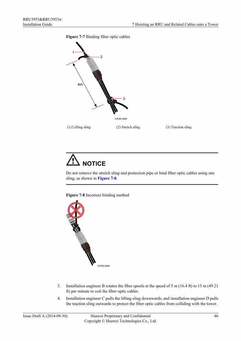
Figure 7-7 Binding fiber optic cables
(1) Lifting sling (2) Stretch sling (3) Traction sling
NOTICEDo not remove the stretch sling and protection pipe or bind fiber optic cables using onesling, as shown in Figure 7-8.
Figure 7-8 Incorrect binding method
3. Installation engineer B rotates the fiber spools at the speed of 5 m (16.4 ft) to 15 m (49.21ft) per minute to coil the fiber optic cables.
4. Installation engineer C pulls the lifting sling downwards, and installation engineer D pullsthe traction sling outwards to protect the fiber optic cables from colliding with the tower.
RRU3953&RRU3953wInstallation Guide 7 Hoisting an RRU and Related Cables onto a Tower
Issue Draft A (2014-09-30) Huawei Proprietary and ConfidentialCopyright © Huawei Technologies Co., Ltd.
46

Step 2 Secure the fiber optic cables to the tower vertically using cable clips.
Step 3 Remove the lifting sling, traction sling, and protection pipe.
NOTE
The procedure for hoisting the fiber optic cables onto the tower is for your reference only.
----End
7.3 Hoisting Power Cables onto a TowerThis section describes the procedure for hoisting power cables onto a tower and the precautionsthat must be taken.
ContextCabling requirements for power cables are met. For details, see 9.1 Cabling Requirements.
The procedure for adding a connector to the RRU power cable on the RRU side is done underthe tower.
Procedure
Step 1 Hoist the power cables onto the tower, as shown in Figure 7-9.
Figure 7-9 Hoisting power cables onto the tower
(1) Lifting sling (2) Fixed pulley
RRU3953&RRU3953wInstallation Guide 7 Hoisting an RRU and Related Cables onto a Tower
Issue Draft A (2014-09-30) Huawei Proprietary and ConfidentialCopyright © Huawei Technologies Co., Ltd.
47

1. After climbing up to the tower, installation engineer A secures the fixed pulley to the towerplatform support and leads the lifting sling through the fixed pulley.
2. Installation engineer B secures three cable ties to the power cable connector, and thensecures the power cable to the lifting sling, as shown in Figure 7-10.
NOTE
The connector on the power cable in the figure is only an example. The actual connector may varyaccording to the situation.
Figure 7-10 Binding cable ties
3. Installation engineer B wraps the power cable connector with a layer of PVC insulation
tape, as shown in Figure 7-11.
NOTE
Wrap the PVC insulation tape from 30 mm (1.18 in.) away from one end of the connector until itreaches the other end of the connector. The total length of the wrapped connector is 100 mm (3.94in.).
RRU3953&RRU3953wInstallation Guide 7 Hoisting an RRU and Related Cables onto a Tower
Issue Draft A (2014-09-30) Huawei Proprietary and ConfidentialCopyright © Huawei Technologies Co., Ltd.
48

Figure 7-11 Wrapping the PVC insulation tape
4. Installation engineer C pulls the lifting sling downwards, and installation engineer B pulls
the other end of the lifting sling outwards to protect the power cables from colliding withthe tower.
Step 2 Secure the power cables to the tower vertically using cable clips.
Step 3 Remove the cable ties, PVC insulation tape, and lifting sling.
NOTE
The procedure for hoisting the power cables onto the tower is for your reference only.
----End
RRU3953&RRU3953wInstallation Guide 7 Hoisting an RRU and Related Cables onto a Tower
Issue Draft A (2014-09-30) Huawei Proprietary and ConfidentialCopyright © Huawei Technologies Co., Ltd.
49

8 Installing the RRU
About This Chapter
This chapter describes the procedure for installing the RRU. The procedure for installing theRRU varies depending on installation options.
8.1 Mounting Kits for an RRUThis section describes the bracket assembly and the attachment plate for an RRU.
8.2 Installing the RRU on a PoleOne or more RRUs can be installed on a pole.
8.3 Installing an RRU on U-steelThis section describes the procedure and precautions for installing an RRU on U-steel. An RRUcan be installed on U-steel secured on the ground or a tower. Each piece of U-steel allows onlyone RRU to be installed in standard or reverse mode.
8.4 Installing an RRU on Angle SteelThis section describes the procedure and precautions for installing an RRU on angle steel. AnRRU can be installed on angle steel secured on the ground or a tower. Each piece of angle steelallows only one RRU to be installed in standard or reverse mode.
8.5 Installing an RRU on a WallThis section describes the procedure and precautions for installing an RRU on a wall.
8.6 Installing an RRU on an IFS06This section describes the procedure and precautions for installing an RRU on an IFS06.
RRU3953&RRU3953wInstallation Guide 8 Installing the RRU
Issue Draft A (2014-09-30) Huawei Proprietary and ConfidentialCopyright © Huawei Technologies Co., Ltd.
50

8.1 Mounting Kits for an RRUThis section describes the bracket assembly and the attachment plate for an RRU.
Figure 8-1 shows the front and side of an RRU.
Figure 8-1 Front and side view of an RRU
(1) Front view (2) Side view (3) Attachment plate
Figure 8-2 shows the bracket assembly for an RRU.
Figure 8-2 18 L blade RRU mounting kit
(1) Plastic cap (2) Standard M10 nut (3) Spring washer (4) Thick flat washer (5) Square-neck bolt
RRU3953&RRU3953wInstallation Guide 8 Installing the RRU
Issue Draft A (2014-09-30) Huawei Proprietary and ConfidentialCopyright © Huawei Technologies Co., Ltd.
51

(6) Hoist clamp onthe main bracket
(7) Main bracket (8) Inner hexagonscrew
(9) Pole installationbracket
(10) Auxiliarybracket
8.2 Installing the RRU on a PoleOne or more RRUs can be installed on a pole.
8.2.1 Installing a Single RRUThis section describes the procedure and precautions for installing a single RRU on a pole.
PrerequisitesBefore you install an RRU on a pole secured on a tower, the RRU and its mounting brackets arehoisted onto the tower. For details, see 7.1 Hoisting an RRU onto a Tower.
The hoist clamp on the main bracket is secured properly.
NOTICEl Do not stand an RRU upright because the RF ports cannot support the weight of the RRU.l Place a foam pad or cardboard under an RRU to protect the RRU housing from damage
during the installation.
Procedure
Step 1 Determine a position for installing the mounting brackets.l If the RRU is installed on a tower, determine a position for installing the mounting brackets
according to the instructions in 3.5.1 Clearance for a Single RRU.l If the RRU is installed on the ground, determine a position for installing the mounting
brackets according to Figure 8-3.
RRU3953&RRU3953wInstallation Guide 8 Installing the RRU
Issue Draft A (2014-09-30) Huawei Proprietary and ConfidentialCopyright © Huawei Technologies Co., Ltd.
52

Figure 8-3 Distance between the mounting brackets and the ground
NOTE
As shown in the figure above, it is recommended that the mounting kits be installed at a position1200 mm (47.24 in.) to 1600 mm (59.06 in.) high above the ground. If the space is insufficient, onlythe 3.5 Installation Clearance Requirements of an RRU needs to be provided.
Step 2 Install the RRU mounting brackets, as shown in Figure 8-4.
Figure 8-4 Installing the RRU mounting brackets
NOTE
Ensure that the arrows on the mounting brackets are pointing up.
1. Adjust the position of the nut and remove the square-neck bolt at the open end from theslot on the auxiliary bracket.
2. Slide the mounting brackets onto the pole horizontally and insert the square-neck bolt intothe slot.
RRU3953&RRU3953wInstallation Guide 8 Installing the RRU
Issue Draft A (2014-09-30) Huawei Proprietary and ConfidentialCopyright © Huawei Technologies Co., Ltd.
53

Step 3 Use a 16 mm (0.63 in.) M10 torque wrench to tighten the nuts to 40 N·m (354.03 lbf·in.) so thatthe mounting brackets are secured onto the pole, as shown in Figure 8-5.
NOTICETighten the nuts on the two square-neck bolts simultaneously. After the main and auxiliarybrackets are secured properly, measure the spacing between the brackets on both sides and ensurethat the spacing is the same on the two sides.
Figure 8-5 Securing the RRU mounting brackets
(1) Plastic cap
Step 4 Install the RRU onto the main bracket, as shown in Figure 8-6.
RRU3953&RRU3953wInstallation Guide 8 Installing the RRU
Issue Draft A (2014-09-30) Huawei Proprietary and ConfidentialCopyright © Huawei Technologies Co., Ltd.
54

Figure 8-6 Installing the RRU onto the main bracket
Step 5 Use an inner hexagon torque screwdriver to tighten the captive screw into the holes on the topof the attachment plate and main bracket to 5 N·m (44.25 lbf·in.) so that the attachment plateand main bracket are firmly secured, as shown in Figure 8-7.
Figure 8-7 Securing the captive screw into the connection hole
----End
8.2.2 Installing Two RRUsThis section describes the procedure and precautions for installing two RRUs on a pole.
RRU3953&RRU3953wInstallation Guide 8 Installing the RRU
Issue Draft A (2014-09-30) Huawei Proprietary and ConfidentialCopyright © Huawei Technologies Co., Ltd.
55

PrerequisitesThe hoist clamp on the main bracket is secured properly.
NOTICEl Do not stand an RRU upright because the RF ports cannot support the weight of the RRU.l Place a foam pad or cardboard under an RRU to protect the RRU housing from damage
during the installation.
Procedure
Step 1 Install the first RRU onto the main bracket, as shown in Figure 8-8. For details, see 8.2.1Installing a Single RRU.
Figure 8-8 Installing the first RRU onto the main bracket
Step 2 Use an M6 inner hexagon screwdriver to loosen the four hex socket screws from the main bracketand pole installation brackets on the second set of mounting brackets, and remove the mainbracket, as shown in Figure 8-9.
RRU3953&RRU3953wInstallation Guide 8 Installing the RRU
Issue Draft A (2014-09-30) Huawei Proprietary and ConfidentialCopyright © Huawei Technologies Co., Ltd.
56

Figure 8-9 Removing the RRU main bracket
(1) Main bracket (2) Pole installation bracket
Step 3 Install the removed main bracket on one side of the first main bracket, as shown in Figure8-10.
NOTICEThe second main bracket must be installed, with the open ends of U-shaped slots on both sidesfacing downwards.
Figure 8-10 Installing the second main bracket
(1) Removed main bracket
RRU3953&RRU3953wInstallation Guide 8 Installing the RRU
Issue Draft A (2014-09-30) Huawei Proprietary and ConfidentialCopyright © Huawei Technologies Co., Ltd.
57

NOTE
The main mounting bracket for installing a blade RRU can connect to the main mounting bracket forinstalling a common RRU in the scenarios of adding RRUs, as shown in Figure 8-11.
Figure 8-11 Connect to the main mounting bracket for installing a common RRU
(1) Main mounting bracket for a blade RRU (2) Main mounting bracket for a common RRU
Step 4 Install the second RRU onto the main bracket, as shown in Figure 8-12.
RRU3953&RRU3953wInstallation Guide 8 Installing the RRU
Issue Draft A (2014-09-30) Huawei Proprietary and ConfidentialCopyright © Huawei Technologies Co., Ltd.
58

Figure 8-12 Installing the second RRU onto the main bracket
NOTICEAfter installing each RRU on its main bracket, use an inner hexagon torque screwdriver to tightenthe captive screw into the holes of the attachment plate and main bracket to 5 N·m (44.25 lbf·in.)so that the attachment plate and main bracket are firmly secured, as shown in Figure 8-13
RRU3953&RRU3953wInstallation Guide 8 Installing the RRU
Issue Draft A (2014-09-30) Huawei Proprietary and ConfidentialCopyright © Huawei Technologies Co., Ltd.
59

Figure 8-13 Securing the captive screw into the connection hole
Step 5 Install the sheet metal tab for fixing the neighboring RRUs, as shown in Figure 8-14.
Figure 8-14 Installing the sheet metal tab
(1) Screw (2) Sheet metal tab
1. Use an M6 Phillips screwdriver to loosen the screw on the sheet metal tab farther from the
handle of the second RRU and remove the screw.
RRU3953&RRU3953wInstallation Guide 8 Installing the RRU
Issue Draft A (2014-09-30) Huawei Proprietary and ConfidentialCopyright © Huawei Technologies Co., Ltd.
60

2. Use an M6 Phillips screwdriver to loosen the screw on the sheet metal tab closer to thehandle of the second RRU. Then, rotate the sheet metal tab to align the vacant hole in thesheet metal tab with a hole on the top of the first RRU.
3. Insert the removed screw into the hole on the top of the first RRU and use an M6 torquescrewdriver to tighten the screw to 5 N·m (44.25 lbf·in.).
----End
8.2.3 Installing Three or More RRUsThis section describes the procedure and precautions for installing three or more RRUs on apole.
PrerequisitesThe hoist clamp on the main bracket is secured properly.
NOTICEl Do not stand an RRU upright because the RF ports cannot support the weight of the RRU.l Place a foam pad or cardboard under an RRU to protect the RRU housing from damage
during the installation.
ContextA pole supports three, four, or six RRUs. The procedures for installing them are the same. Thefollowing provides an example for the procedure of installing four RRUs on a pole.
Procedure
Step 1 Install two RRUs, as shown in Figure 8-15. For detailed installation process, see 8.2.2 InstallingTwo RRUs.
RRU3953&RRU3953wInstallation Guide 8 Installing the RRU
Issue Draft A (2014-09-30) Huawei Proprietary and ConfidentialCopyright © Huawei Technologies Co., Ltd.
61

Figure 8-15 Two RRUs installed on a pole
Step 2 Use an M6 inner hexagon screwdriver to loosen the four hex socket screws from the main bracketand pole installation brackets on the second set of mounting brackets, and remove the mainbracket, as shown in Figure 8-16.
Figure 8-16 Removing the RRU main bracket
(1) Main bracket (2) Pole installation bracket
Step 3 Install the third main bracket and install the third RRU onto the third main bracket. Then, usean inner hexagon torque screwdriver to tighten the captive screw into the holes on the top of theattachment plate and main bracket for the RRU to 5 N·m (44.25 lbf·in.), as shown in Figure8-17.
RRU3953&RRU3953wInstallation Guide 8 Installing the RRU
Issue Draft A (2014-09-30) Huawei Proprietary and ConfidentialCopyright © Huawei Technologies Co., Ltd.
62

NOTICEThe third main bracket must be installed, with the open ends of U-shaped slots on both sidesfacing downwards.
Figure 8-17 Installing the third RRU onto the third main bracket
NOTE
The main mounting bracket for installing a blade RRU can connect to the main mounting bracket forinstalling a common RRU in the scenarios of adding RRUs, as shown in Figure 8-18.
RRU3953&RRU3953wInstallation Guide 8 Installing the RRU
Issue Draft A (2014-09-30) Huawei Proprietary and ConfidentialCopyright © Huawei Technologies Co., Ltd.
63

Figure 8-18 Connect to the main mounting bracket for installing a common RRU
(1) Main mounting bracket for a blade RRU (2) Main mounting bracket for a common RRU
Step 4 Install the sheet metal tab for fixing the neighboring RRUs, as shown in Figure 8-19.
Figure 8-19 Installing the sheet metal tab
(1) Screw (2) Sheet metal tab
1. Use an M6 Phillips screwdriver to loosen the screw on the sheet metal tab farther from thehandle of the first RRU and remove the screw.
2. Use an M6 Phillips screwdriver to loosen the screw on the sheet metal tab closer to thehandle of the first RRU. Then, rotate the sheet metal tab to align the vacant hole in the sheetmetal tab with a hole on the top of the third RRU.
RRU3953&RRU3953wInstallation Guide 8 Installing the RRU
Issue Draft A (2014-09-30) Huawei Proprietary and ConfidentialCopyright © Huawei Technologies Co., Ltd.
64

3. Insert the removed screw into the hole on the top of the third RRU and use an M6 torquescrewdriver to tighten the screw to 5 N·m (44.25 lbf·in.).
Step 5 Install the second set of RRU mounting brackets at least 80 mm (3.15 in.) above or below thefirst set of RRU mounting brackets, as shown in Figure 8-20.
Figure 8-20 Installing the second set of RRU mounting brackets
Step 6 Install the fourth RRU onto the fourth main bracket, use an inner hexagon torque screwdriverto tighten the captive screw into the holes on the top of the attachment plate and main bracketto 5 N·m (44.25 lbf·in.) so that the attachment plate and main bracket are firmly secured, asshown in Figure 8-21.
RRU3953&RRU3953wInstallation Guide 8 Installing the RRU
Issue Draft A (2014-09-30) Huawei Proprietary and ConfidentialCopyright © Huawei Technologies Co., Ltd.
65

Figure 8-21 Installing the fourth RRU on the fourth main bracket
----End
8.3 Installing an RRU on U-steelThis section describes the procedure and precautions for installing an RRU on U-steel. An RRUcan be installed on U-steel secured on the ground or a tower. Each piece of U-steel allows onlyone RRU to be installed in standard or reverse mode.
Prerequisites
Before you install an RRU on U-steel secured on a tower, the RRU and its mounting bracketsare hoisted onto the tower. For details, see 7.1 Hoisting an RRU onto a Tower.
The hoist clamp on the main bracket is secured properly.
NOTICEl Do not stand an RRU upright because the RF ports cannot support the weight of the RRU.
l Place a foam pad or cardboard under an RRU to protect the RRU housing from damageduring the installation.
Context
Figure 8-22 shows the top view of an RRU installed on U-steel.
RRU3953&RRU3953wInstallation Guide 8 Installing the RRU
Issue Draft A (2014-09-30) Huawei Proprietary and ConfidentialCopyright © Huawei Technologies Co., Ltd.
66

NOTICEWhen the width of the narrower edges of the U-steel is less than 40 mm (1.57 in.), only the aand b modes are supported.
Figure 8-22 Top view of an RRU
(1) U-steel
Procedure
Step 1 Determine a position for installing the mounting brackets.l If the RRU is installed on a tower, determine a position for installing the mounting brackets
according to the instructions in 3.5.1 Clearance for a Single RRU.l If the RRU is installed on the ground, determine a position for installing the mounting
brackets according to the instructions in Figure 8-23.
RRU3953&RRU3953wInstallation Guide 8 Installing the RRU
Issue Draft A (2014-09-30) Huawei Proprietary and ConfidentialCopyright © Huawei Technologies Co., Ltd.
67
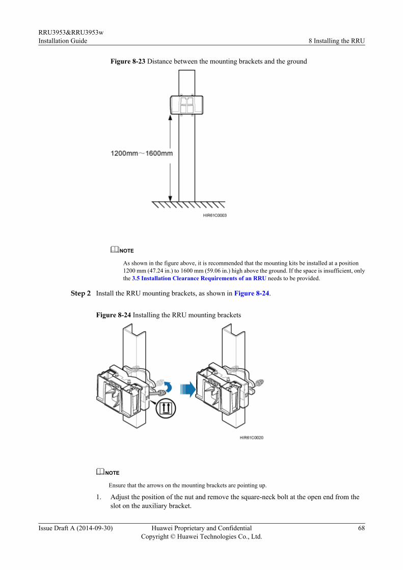
Figure 8-23 Distance between the mounting brackets and the ground
NOTE
As shown in the figure above, it is recommended that the mounting kits be installed at a position1200 mm (47.24 in.) to 1600 mm (59.06 in.) high above the ground. If the space is insufficient, onlythe 3.5 Installation Clearance Requirements of an RRU needs to be provided.
Step 2 Install the RRU mounting brackets, as shown in Figure 8-24.
Figure 8-24 Installing the RRU mounting brackets
NOTE
Ensure that the arrows on the mounting brackets are pointing up.
1. Adjust the position of the nut and remove the square-neck bolt at the open end from theslot on the auxiliary bracket.
RRU3953&RRU3953wInstallation Guide 8 Installing the RRU
Issue Draft A (2014-09-30) Huawei Proprietary and ConfidentialCopyright © Huawei Technologies Co., Ltd.
68

2. Slide the mounting brackets onto the U-steel horizontally and insert the square-neck boltinto the slot.
Step 3 Use a 16 mm (0.67 in.) M10 torque wrench to tighten the nuts to 40 N·m (354.03 lbf·in.) so thatthe mounting brackets are secured onto the U-steel, as shown in Figure 8-25.
NOTICETighten the nuts on the two square-neck bolts simultaneously. After the main and auxiliarybrackets are secured properly, measure the spacing between the brackets on both sides and ensurethat the spacing is the same on the two sides.
Figure 8-25 Securing the RRU mounting brackets
(1) Plastic cap
Step 4 Use an inner hexagon torque screwdriver to remove the attachment plate from one side of theRRU, reinstall the attachment plate onto the rear of the RRU, and tighten the four stainless screwsto 5 N·m (44.25 lbf·in.), as shown in Figure 8-26.
RRU3953&RRU3953wInstallation Guide 8 Installing the RRU
Issue Draft A (2014-09-30) Huawei Proprietary and ConfidentialCopyright © Huawei Technologies Co., Ltd.
69
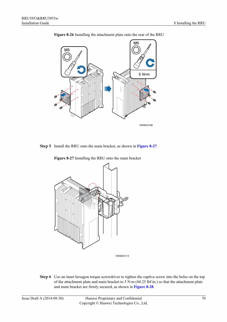
Figure 8-26 Installing the attachment plate onto the rear of the RRU
Step 5 Install the RRU onto the main bracket, as shown in Figure 8-27.
Figure 8-27 Installing the RRU onto the main bracket
Step 6 Use an inner hexagon torque screwdriver to tighten the captive screw into the holes on the topof the attachment plate and main bracket to 5 N·m (44.25 lbf·in.) so that the attachment plateand main bracket are firmly secured, as shown in Figure 8-28.
RRU3953&RRU3953wInstallation Guide 8 Installing the RRU
Issue Draft A (2014-09-30) Huawei Proprietary and ConfidentialCopyright © Huawei Technologies Co., Ltd.
70

Figure 8-28 Securing the captive screw into the connection hole
----End
8.4 Installing an RRU on Angle SteelThis section describes the procedure and precautions for installing an RRU on angle steel. AnRRU can be installed on angle steel secured on the ground or a tower. Each piece of angle steelallows only one RRU to be installed in standard or reverse mode.
Prerequisites
Before you install an RRU on U-steel secured on a tower, the RRU and its mounting bracketsare hoisted onto the tower. For details, see 7.1 Hoisting an RRU onto a Tower.
The hoist clamp on the main bracket is secured properly.
NOTICEl Do not stand an RRU upright because the RF ports cannot support the weight of the RRU.
l Place a foam pad or cardboard under an RRU to protect the RRU housing from damageduring the installation.
Context
Figure 8-29 shows the top view of an RRU installed on angle steel.
RRU3953&RRU3953wInstallation Guide 8 Installing the RRU
Issue Draft A (2014-09-30) Huawei Proprietary and ConfidentialCopyright © Huawei Technologies Co., Ltd.
71

Figure 8-29 Top view of an RRU
(1) Angle steel
Procedure
Step 1 Determine a position for installing the mounting brackets.
l If the RRU is installed on angle steel secured on a tower, determine a position for installingthe mounting brackets according to the instructions in 3.5.1 Clearance for a SingleRRU.
l If the RRU is installed on angle steel secured on the ground, determine a position forinstalling the mounting brackets according to Figure 8-30.
Figure 8-30 Distance between the mounting brackets and the ground
RRU3953&RRU3953wInstallation Guide 8 Installing the RRU
Issue Draft A (2014-09-30) Huawei Proprietary and ConfidentialCopyright © Huawei Technologies Co., Ltd.
72

NOTE
As shown in the figure above, it is recommended that the mounting kits be installed at a position1200 mm (47.24 in.) to 1600 mm (59.06 in.) high above the ground. If the space is insufficient, onlythe 3.5 Installation Clearance Requirements of an RRU needs to be provided.
Step 2 Install the RRU mounting brackets, as shown in Figure 8-31.
Figure 8-31 Installing the RRU mounting brackets
NOTE
Ensure that the arrows on the mounting brackets are pointing up.
1. Adjust the position of the nut and remove the square-neck bolt at the open end from theslot on the auxiliary bracket.
2. Slide the mounting brackets onto the angle steel horizontally and insert the square-neckbolt into the slot.
Step 3 Use a 16 mm (0.67 in.) M10 torque wrench to tighten the nuts to 40 N·m (354.03 lbf·in.) so thatthe mounting brackets are secured onto the angle steel, as shown in Figure 8-32.
NOTICETighten the nuts on the two square-neck bolts synchronously. After the main and auxiliarybrackets are secured properly, measure the spacing between the brackets on both sides and ensurethat the spacing is the same on the two sides.
RRU3953&RRU3953wInstallation Guide 8 Installing the RRU
Issue Draft A (2014-09-30) Huawei Proprietary and ConfidentialCopyright © Huawei Technologies Co., Ltd.
73

Figure 8-32 Securing the RRU mounting brackets
(1) Plastic cap
Step 4 Use an inner hexagon torque screwdriver to remove the attachment plate from one side of theRRU, reinstall the attachment plate onto the rear of the RRU, and tighten the four stainless screwsto 5 N·m (44.25 lbf·in.), as shown in Figure 8-33.
Figure 8-33 Installing the attachment plate onto the rear of the RRU
RRU3953&RRU3953wInstallation Guide 8 Installing the RRU
Issue Draft A (2014-09-30) Huawei Proprietary and ConfidentialCopyright © Huawei Technologies Co., Ltd.
74

Step 5 Install the RRU onto the main bracket, as shown in Figure 8-34.
Figure 8-34 Installing the RRU onto the main bracket
Step 6 Use an inner hexagon torque screwdriver to tighten the captive screw into the holes on the topof the attachment plate and main bracket to 5 N·m (44.25 lbf·in.) so that the attachment plateand main bracket are firmly secured, as shown in Figure 8-35.
Figure 8-35 Securing the captive screw into the connection hole
RRU3953&RRU3953wInstallation Guide 8 Installing the RRU
Issue Draft A (2014-09-30) Huawei Proprietary and ConfidentialCopyright © Huawei Technologies Co., Ltd.
75
----End
8.5 Installing an RRU on a WallThis section describes the procedure and precautions for installing an RRU on a wall.
PrerequisitesThe hoist clamp on the main bracket is secured properly.
NOTICEl Do not stand an RRU upright because the RF ports cannot support the weight of the RRU.l Place a foam pad or cardboard under an RRU to protect the RRU housing from damage
during the installation.
ContextThe wall on which RRUs are installed must meet the following requirements:l For each RRU, the wall must be able to bear a weight four times heavier than the RRU's
weight and the bolts' pulling force of 1.25 kN (281.25 lbf) vertical to the wall.l Expansion bolts must be tightened to 30 N·m to ensure that the bolts work properly and the
wall remains intact.
Procedure
Step 1 Disassemble the RRU mounting brackets, as shown in Figure 8-36.
RRU3953&RRU3953wInstallation Guide 8 Installing the RRU
Issue Draft A (2014-09-30) Huawei Proprietary and ConfidentialCopyright © Huawei Technologies Co., Ltd.
76

Figure 8-36 Disassembling the RRU mounting brackets
(1) Main bracket (2) Square-neck bolt (3) Pole installation bracket (4) Auxiliary bracket
(5) Flat washer (6) Spring washer (7) Nut (8) Plastic screw cap
1. Use an M6 inner hexagon torque screwdriver to remove the four inner hexagon screws on
the pole installation bracket, and remove the main bracket from the pole installation bracket.2. Use an M10 torque wrench to loosen the nuts on the two square-neck bolts, and remove
the plastic screw cap, nuts, spring washers, flat washers, square-neck bolts, and poleinstallation bracket from the auxiliary bracket.
Step 2 Place the pole installation bracket against the wall, use a level to verify that the pole installationbracket is placed horizontally, and then mark anchor points with a marker, as shown in Figure8-37.
RRU3953&RRU3953wInstallation Guide 8 Installing the RRU
Issue Draft A (2014-09-30) Huawei Proprietary and ConfidentialCopyright © Huawei Technologies Co., Ltd.
77
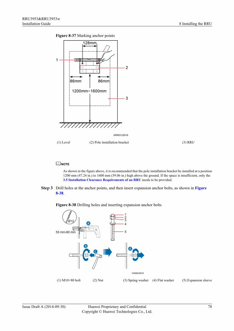
Figure 8-37 Marking anchor points
(1) Level (2) Pole installation bracket (3) RRU
NOTE
As shown in the figure above, it is recommended that the pole installation bracket be installed at a position1200 mm (47.24 in.) to 1600 mm (59.06 in.) high above the ground. If the space is insufficient, only the3.5 Installation Clearance Requirements of an RRU needs to be provided.
Step 3 Drill holes at the anchor points, and then insert expansion anchor bolts, as shown in Figure8-38.
Figure 8-38 Drilling holes and inserting expansion anchor bolts
(1) M10×80 bolt (2) Nut (3) Spring washer (4) Flat washer (5) Expansion sleeve
RRU3953&RRU3953wInstallation Guide 8 Installing the RRU
Issue Draft A (2014-09-30) Huawei Proprietary and ConfidentialCopyright © Huawei Technologies Co., Ltd.
78

1. Use a hammer drill with a Ф12 bit to drill holes vertically at the marked anchor points withthe depth ranging from 55 mm (2.17 in.) to 60 mm (2.36 in.), use a vacuum cleaner to clearthe dust out from inside and around the holes, and measure the distances between holes. Ifany of the hole is beyond the acceptable range, mark a new anchor point and drill a newhole.
NOTICETake proper safety measures to protect your eyes and respiratory tract against the dustbefore drilling holes.
2. Tighten the expansion anchor bolts slightly and place one vertically into each hole.
3. Use a rubber mallet to pound the expansion anchor bolt until it goes into the hole completely.
4. Tighten and then loosen the expansion bolt, and remove the M10 bolt, spring washer, andflat washer in sequence.
NOTICEAfter dismantling an expansion anchor bolt, ensure that the top of the expansion sleeve ison the same level as the wall. Otherwise, the device cannot be installed on the wall evenlyand securely.
Step 4 Install the pole installation bracket on the expansion anchor bolts, place the flat washers, springwashers, and nuts through the expansion anchor bolts in sequence, and then use a 16 mm (0.63in.) torque socket to tighten the nuts to 30 N·m (265.52 lbf·in.), as shown in Figure 8-39.
Figure 8-39 Installing the pole installation bracket on the expansion anchor bolts
RRU3953&RRU3953wInstallation Guide 8 Installing the RRU
Issue Draft A (2014-09-30) Huawei Proprietary and ConfidentialCopyright © Huawei Technologies Co., Ltd.
79

NOTICEEnsure that the arrows on the pole installation bracket are pointing up.
Step 5 Install the main bracket onto the pole installation bracket using four M6x16 inner hexagonscrews, and use an inner hexagon torque screwdriver to tighten the inner hexagon screws to 5N·m (44.25 lbf·in.) so that the main bracket and pole installation bracket are firmly secured, asshown in Figure 8-40.
Figure 8-40 Installing the main bracket
(1) Main bracket (2) Pole installation bracket
Step 6 Use an inner hexagon torque screwdriver to remove the attachment plate from one side of theRRU, reinstall the attachment plate onto the rear of the RRU, and tighten the four stainless screwsto 5 N·m (44.25 lbf·in.), as shown in Figure 8-41.
RRU3953&RRU3953wInstallation Guide 8 Installing the RRU
Issue Draft A (2014-09-30) Huawei Proprietary and ConfidentialCopyright © Huawei Technologies Co., Ltd.
80

Figure 8-41 Installing the attachment plate onto the rear of the RRU
Step 7 Install the RRU onto the main bracket, as shown in Figure 8-42.
Figure 8-42 Installing the RRU onto the main bracket
Step 8 Use an inner hexagon torque screwdriver to tighten the captive screw into the holes on the topof the attachment plate and main bracket to 5 N·m (44.25 lbf·in.) so that the attachment plateand main bracket are firmly secured, as shown in Figure 8-43.
RRU3953&RRU3953wInstallation Guide 8 Installing the RRU
Issue Draft A (2014-09-30) Huawei Proprietary and ConfidentialCopyright © Huawei Technologies Co., Ltd.
81

Figure 8-43 Securing the captive screw into the connection hole
----End
8.6 Installing an RRU on an IFS06This section describes the procedure and precautions for installing an RRU on an IFS06.
PrerequisitesThe hoist clamp on the main bracket is secured properly.
NOTICEl Do not stand an RRU upright because the RF ports cannot support the weight of the RRU.l Place a foam pad or cardboard under an RRU to protect the RRU housing from damage
during the installation.
Contextl The upper and lower adjustable beams on an IFS06 can be moved up and down to fit for
heights of RRUs.l RRUs can be installed on an IFS06 when the ambient temperature is higher than or equal
to the lowest operating temperature of the RRUs and at least 5°C (41°F) lower than thehighest working temperature of the RRU. In this scenario, the IFS06 supports at least threeRRUs. The IFS06 supports a maximum of six RRUs when the ambient temperature is higher
RRU3953&RRU3953wInstallation Guide 8 Installing the RRU
Issue Draft A (2014-09-30) Huawei Proprietary and ConfidentialCopyright © Huawei Technologies Co., Ltd.
82

than or equal to the lowest operating temperature of the RRUs and at least 10°C (50°F)lower than the highest operating temperature of the RRU.
NOTE
For details about the operating temperature of the RRUs, see section "Technical Specifications ofRRUs" in 3900 Series Base Station Technical Description.
l Install RRUs in the sequence from bottom to top and from left to right.l This section describes how to install an RRU in height-unrestricted scenarios. The
procedure for installing an RRU in height-restricted scenarios is the same as that in height-unrestricted scenarios.
l When installing the pole installation bracket, you need to use the M10x50 bolts deliveredwith the IFS06.
l Rubber washers are easily compressed or broken, whereas do not need to be replaced.
Procedure
Step 1 Disassemble the RRU mounting brackets, as shown in Figure 8-44.
Figure 8-44 Disassembling the RRU mounting brackets
(1) Main bracket (2) Square-neck bolt (3) Pole installation bracket (4) Auxiliary bracket
(5) Flat washer (6) Spring washer (7) Nut (8) Plastic screw cap
1. Use an M6 inner hexagon torque screwdriver to remove the four inner hexagon screws on
the pole installation bracket, and remove the main bracket from the pole installation bracket.2. Use an M10 torque wrench to loosen the nuts on the two square-neck bolts, and remove
the plastic screw cap, nuts, spring washers, flat washers, square-neck bolts, and poleinstallation bracket from the auxiliary bracket.
Step 2 Use the M10x50 bolts delivered with the IFS06 to secure the pole installation bracket to theIFS06, and then use an M10 torque socket wrench to secure the bolts to 30 N·m (265.52 lbf·in.).
RRU3953&RRU3953wInstallation Guide 8 Installing the RRU
Issue Draft A (2014-09-30) Huawei Proprietary and ConfidentialCopyright © Huawei Technologies Co., Ltd.
83

NOTICEEnsure that the arrows on the pole installation bracket are pointing up.
Install the pole installation bracket, as shown in Figure 8-45.
Figure 8-45 Installing the pole installation bracket in height-unrestricted scenarios
(1) Spring washer (2) Rubber washer
Step 3 Attach the main bracket to the pole installation bracket, and use an inner hexagon screwdriverto tighten four M6x16 screws to 5 N·m (44.25 lbf·in.) so that the main bracket and poleinstallation bracket are firmly secured, as shown in Figure 8-46.
RRU3953&RRU3953wInstallation Guide 8 Installing the RRU
Issue Draft A (2014-09-30) Huawei Proprietary and ConfidentialCopyright © Huawei Technologies Co., Ltd.
84

Figure 8-46 Installing the main bracket
(1) Main bracket (2) Pole installation bracket
Step 4 Attach the RRU to the main bracket, and then use an inner hexagon screwdriver to tighten thecaptive screw into the holes of the attachment plate and main bracket to 5 N·m (44.25 lbf·in.) sothat the attachment plate and main bracket are firmly secured, as shown in Figure 8-47.
RRU3953&RRU3953wInstallation Guide 8 Installing the RRU
Issue Draft A (2014-09-30) Huawei Proprietary and ConfidentialCopyright © Huawei Technologies Co., Ltd.
85

Figure 8-47 Installing the RRU onto the main bracket
Step 5 Install the RRUs on the lower level from left to right, as shown in Figure 8-48.
RRU3953&RRU3953wInstallation Guide 8 Installing the RRU
Issue Draft A (2014-09-30) Huawei Proprietary and ConfidentialCopyright © Huawei Technologies Co., Ltd.
86

Figure 8-48 Installing RRUs on the lower level
Step 6 Optional: Optional: When the ambient temperature is equal to or higher than the lowestoperating temperature of the RRU and at least 10°C (10°F) lower than the highest operatingtemperature of the RRU, repeat the preceding steps to install the RRUs on the higher level, asshown in Figure 8-49.
RRU3953&RRU3953wInstallation Guide 8 Installing the RRU
Issue Draft A (2014-09-30) Huawei Proprietary and ConfidentialCopyright © Huawei Technologies Co., Ltd.
87

Figure 8-49 Installing RRUs on the higher level
----End
RRU3953&RRU3953wInstallation Guide 8 Installing the RRU
Issue Draft A (2014-09-30) Huawei Proprietary and ConfidentialCopyright © Huawei Technologies Co., Ltd.
88
9 Installing RRU Cables
About This Chapter
This chapter describes the procedure for installing RRU cables.
9.1 Cabling RequirementsCables must be routed according to the specified cabling requirements to prevent signalinterference.
9.2 RRU Cable ConnectionsThis section describes RRU cable connections.
9.3 Installing RRU CablesThis chapter describes the procedure for installing RRU cables.
9.4 RRU CablesThis section describes RRU cable connections.
9.5 Installing an RRU PGND CableThis section describes the procedure for installing an RRU PGND cable.
9.6 Installing an RRU RF JumperThis section describes the procedure for installing an RRU RF jumper.
9.7 Installing an RRU AISG Multi-Wire Cable and AISG Extension CableThis section describes the procedures for installing an RRU AISG multi-wire cable and AISGextension cable.
9.8 Installing an RRU Alarm CableThis section describes the procedure for installing an RRU alarm cable.
9.9 Opening the Cover Plate of an RRU Cabling CavityThis section describes the procedure for opening the cover plate of an RRU cabling cavity.
9.10 Installing a CPRI Optical CableThis section describes the procedure for installing a CPRI optical cable.
9.11 Installing an RRU Power CableThis section describes the procedure for installing an RRU power cable.
9.12 Closing the Cover Plate of an RRU Cabling Cavity
RRU3953&RRU3953wInstallation Guide 9 Installing RRU Cables
Issue Draft A (2014-09-30) Huawei Proprietary and ConfidentialCopyright © Huawei Technologies Co., Ltd.
89
This section describes the procedure for closing the cover plate of an RRU cabling cavity.
RRU3953&RRU3953wInstallation Guide 9 Installing RRU Cables
Issue Draft A (2014-09-30) Huawei Proprietary and ConfidentialCopyright © Huawei Technologies Co., Ltd.
90

9.1 Cabling RequirementsCables must be routed according to the specified cabling requirements to prevent signalinterference.
NOTE
If a cable listed below is not required, skip the routing requirements of the cable.
General Cabling RequirementsRequirements for Bending Radiusl The bending radius of the 7/8'' feeder must be more than 250 mm (9.84 in.), and the bending
radius of the 5/4'' feeder must be more than 380 mm (14.96 in.).l The bending radius of the 1/4'' jumper must be more than 35 mm (1.38 in.). The bending
radius of the super-flexible 1/2'' jumper must be more than 50 mm (1.97 in.), and the bendingradius of the ordinary 1/2'' jumper must be more than 127 mm (5 in.).
l The bending radius of the power cable or PGND cable must be at least three times thediameter of the cable.
l The bending radius of a fiber optic cable is at least 20 times the diameter of the fiber opticcable, and the minimum bending radius of the breakout cable at each end of the fiber opticcable is 30 mm (1.18 in.).
l The bending radius of the E1/T1 cable must be at least three times the diameter of the cable.l The bending radius of the signal cable must be at least five times the diameter of the cable.
Requirements for Cable Bindingl The same types of cable must be bound together.l Different types of cable must be separately routed with the minimum spacing of 30 mm
(1.18 in.) and cannot be entangled.l The cables must be bound tightly and neatly. The sheaths of the cables must not be damaged.l Cable ties are installed in the same direction, and those at the same horizontal line must be
in a straight line.l The excess of indoor cable ties is trimmed off, and the excess of outdoor cable ties allows
about 5 mm (0.2 in.), without remaining rough edges.l Labels or nameplates must be attached to both ends, joints, or turns of cables after they are
installed.
Security Requirementsl Cables should be placed away from sharp objects or wall burrs. If these positions are
inevitable, protect the cables with protection pipes.l Cables must be routed away from heat sources, or heat-insulation materials are added
between cables and heat sources.l Sufficient slack (recommended for about 0.1 m [0.33 ft]) is provided in cables at turns or
the position close to a device, facilitating cable and device maintenance.
Indoor Cabling Requirementsl Cables are routed indoors through the feeder window.
RRU3953&RRU3953wInstallation Guide 9 Installing RRU Cables
Issue Draft A (2014-09-30) Huawei Proprietary and ConfidentialCopyright © Huawei Technologies Co., Ltd.
91

l Drip loops must be made outside the feeder window, and the requirements for the minimumbending radius are met.
l When cables are routed indoors, engineers are required indoors for cooperation.l The feeder window must be waterproofed.
Outdoor Cabling Requirementsl Cables routed outdoors must be led through a pipe when they may be damaged.l AC power cables, transmission cables, and cables buried in the ground must be protected.l If cables at the cabinet bottom need to be routed through a pipe along the ground, lead the
pipe into the cabinet base for about 30 mm (1.18 in.) to 50 mm (1.97 in.), not into thecabinet. Block the pipe with waterproof tape or silicon gel, and secure the pipe to the cablehole at the cabinet bottom with metal piece.
l If cables at the cabinet bottom need to be routed through a pipe along the metal cable trough,do not lead the pipe into the cabinet base. The cable trough must be sealed and routedthrough the cable hole at the cabinet bottom.
l When routing RRU cables, ensure that the highest positions of the routes of all RRU cables(except RF cables and AISG cables) must be lower than the bottom of the RRU.
l Cables are secured with cable clips.l Cables are routed neatly along the specified cabling direction and secured with cable clips.l The positions for cable clips are determined onsite. For example, the cable clips for the
7/8" feeder are installed at the spacing of 1.5 m (4.92 ft) to 2 m (6.56 ft) in the same direction,and the cable clips for the power cables are installed at the spacing of 1.5 m (4.92 ft) to 2m (6.56 ft) in the same direction.
l Cable clips must be vertical with cables, and the cables in a cable clip must be parallel.l After routing cables neatly and correctly, tighten the screws on cable clips.
Secure cables on the cable tray, as shown in Figure 9-1.
RRU3953&RRU3953wInstallation Guide 9 Installing RRU Cables
Issue Draft A (2014-09-30) Huawei Proprietary and ConfidentialCopyright © Huawei Technologies Co., Ltd.
92

Figure 9-1 Securing cables on the cable tray
Secure cables on the tower, as shown in Figure 9-2.
RRU3953&RRU3953wInstallation Guide 9 Installing RRU Cables
Issue Draft A (2014-09-30) Huawei Proprietary and ConfidentialCopyright © Huawei Technologies Co., Ltd.
93
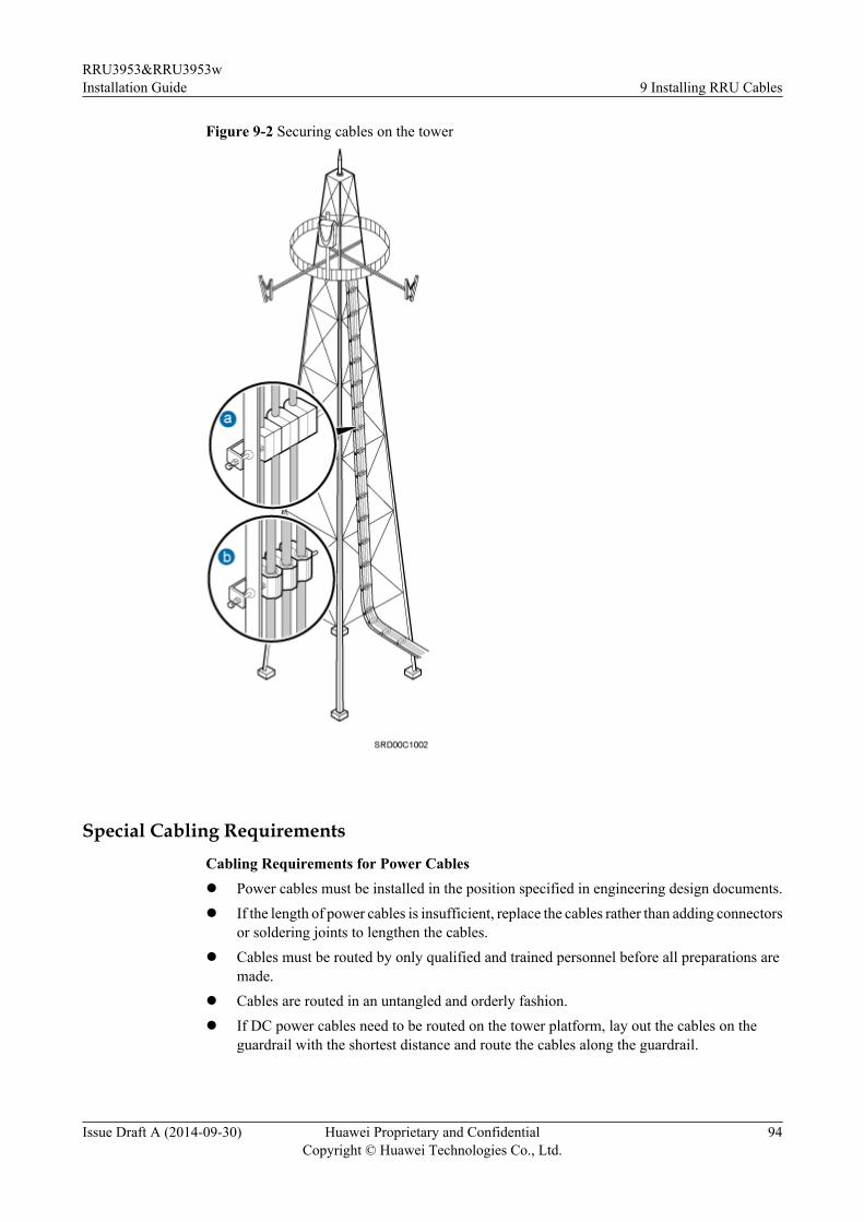
Figure 9-2 Securing cables on the tower
Special Cabling RequirementsCabling Requirements for Power Cablesl Power cables must be installed in the position specified in engineering design documents.l If the length of power cables is insufficient, replace the cables rather than adding connectors
or soldering joints to lengthen the cables.l Cables must be routed by only qualified and trained personnel before all preparations are
made.l Cables are routed in an untangled and orderly fashion.l If DC power cables need to be routed on the tower platform, lay out the cables on the
guardrail with the shortest distance and route the cables along the guardrail.
RRU3953&RRU3953wInstallation Guide 9 Installing RRU Cables
Issue Draft A (2014-09-30) Huawei Proprietary and ConfidentialCopyright © Huawei Technologies Co., Ltd.
94

l If DC power cables need to be routed close to a device on the tower, secure the cables tothe guardrail or pole with cable clips. The device cannot be far away from the position forsecuring the cables.
Cabling Requirements for PGND Cables
l PGND cables for the base station must be connected to the same ground bar.
l PGND cables must be buried in the ground or routed indoors. They should not be routedoverhead before they are led into the equipment room.
l The exterior of the coaxial wire and the shield layer of the shielded cable must have properelectrical contact with the metal surface of the equipment to which they are connected.
l PGND cables and signal cables must be installed in an untangled and orderly fashion. Acertain distance must be reserved between them to prevent interference from each other.
l Fuses or switches must not be installed on the PGND cables.
l Other devices must not be used for electrical connections of the PGND cables.
l All the metal parts in the housing of the equipment must be reliably connected to the groundterminal.
Cabling Requirements for E1 Cables
l E1 cables must not cross power cables, PGND cables, or RF cables when routed. Iftransmission cables are routed with power cables, PGND cables, or RF cables in parallel,the spacing between them must be greater than 30 mm (1.18 in.).
l E1 cables are routed straightly and bound neatly with cable ties.
l Sufficient slack is provided in E1 cables at turns.
l E1 cables cannot be squeezed by the cabinet door when routed through the cabinet, asshown in Figure 9-3.
Figure 9-3 E1 cables routed through the cabinet
Cabling Requirements for Fiber Optic Cables
l Fiber optic cables must be routed by at least three qualified and trained personnel beforeall preparations are made.
l Fiber optic cables are used within the temperature range of -40°C to 60°C. If the currenttemperature is out of the range, make protection measures or route the cables again.
l Cables are routed in an untangled and orderly fashion.
RRU3953&RRU3953wInstallation Guide 9 Installing RRU Cables
Issue Draft A (2014-09-30) Huawei Proprietary and ConfidentialCopyright © Huawei Technologies Co., Ltd.
95

l Do not bind fiber optic cables at turns.l Do not stretch, step on, or place heavy objects on fiber optic cables. Keep the cables away
from sharp objects.l When fiber optic cables are routed, the excess of the cables must be coiled around special
devices, such as a fiber coiler.l An unarmored fiber optic cable must be bound using binding straps. If a fiber optic patch
cord needs to be secured in a cabinet or a piece of equipment, use binding straps to bind itand then use cable ties to secure the binding straps to the cabinet or equipment. Ensure thatthe fiber optic cables can flexibly move in the cable ties. Do not bend the fiber optic cablessharply. The following figure shows how to bind the fiber optic cables correctly.
Figure 9-4 Binding fiber optic cables
l When coiling fiber optic cables, apply even strength. Do not bend the cables with force.l Vacant optical connectors must be covered with dustproof caps.l Fiber optic cables cannot be squeezed by the cabinet door when routed through the cabinet,
as shown in Figure 9-5, Figure 9-6 and Figure 9-7.
Figure 9-5 CPRI fiber optic cables routed through the cabinet (1)
RRU3953&RRU3953wInstallation Guide 9 Installing RRU Cables
Issue Draft A (2014-09-30) Huawei Proprietary and ConfidentialCopyright © Huawei Technologies Co., Ltd.
96

Figure 9-6 CPRI fiber optic cables routed through the cabinet (2)
Figure 9-7 FE/GE cables routed through the cabinet
l If fiber optic cables need to be routed on the tower platform, lay out the cables on the
guardrail with the shortest distance and route the cables along the guardrail.l If fiber optic cables need to be routed close to a device on the tower, secure the cables to
the guardrail or pole with cable clips. The device cannot be far away from the position forsecuring the cables.
l If the fiber optic cables close to a device are too long, coil the excess of the cables andsecure them on the tower.
9.2 RRU Cable ConnectionsThis section describes RRU cable connections.
NOTE
The RRU does not support power cable cascading.
Figure 9-8 shows the cable connections of a single-mode RRU.
RRU3953&RRU3953wInstallation Guide 9 Installing RRU Cables
Issue Draft A (2014-09-30) Huawei Proprietary and ConfidentialCopyright © Huawei Technologies Co., Ltd.
97

Figure 9-8 Cable connections of a single-mode RRU
(1) RRU PGND cable (2) RRU RF jumper (3) RRU AISG multi-wire cable
(4) RRU AISG extension cable (5) RRU power cable (6) CPRI optical fiber
(7) RRU alarm cable - -
Figure 9-9 shows the cable connections of a multimode RRU.
RRU3953&RRU3953wInstallation Guide 9 Installing RRU Cables
Issue Draft A (2014-09-30) Huawei Proprietary and ConfidentialCopyright © Huawei Technologies Co., Ltd.
98

Figure 9-9 Cable connections of a multimode RRU
(1) RRU PGND cable (2) RRU RF jumper (3) RRU AISG multi-wire cable
(4) RRU AISG extension cable (5) RRU power cable (6) CPRI optical fiber
(7) RRU alarm cable - -
Figure 9-10 shows the cable connections of multiple single-mode RRUs.
RRU3953&RRU3953wInstallation Guide 9 Installing RRU Cables
Issue Draft A (2014-09-30) Huawei Proprietary and ConfidentialCopyright © Huawei Technologies Co., Ltd.
99

Figure 9-10 Cable connections of multiple single-mode RRUs
(1) RRU PGND cable (2) RRU RF jumper (3) RRU AISG multi-wire cable
(4) CPRI optical fiber - -
Figure 9-11 shows the cable connections of multiple multimode RRUs.
RRU3953&RRU3953wInstallation Guide 9 Installing RRU Cables
Issue Draft A (2014-09-30) Huawei Proprietary and ConfidentialCopyright © Huawei Technologies Co., Ltd.
100

Figure 9-11 Cable connections of multiple multimode RRUs
9.3 Installing RRU CablesThis chapter describes the procedure for installing RRU cables.
Figure 9-12 shows the procedure for installing RRU cables.
RRU3953&RRU3953wInstallation Guide 9 Installing RRU Cables
Issue Draft A (2014-09-30) Huawei Proprietary and ConfidentialCopyright © Huawei Technologies Co., Ltd.
101

Figure 9-12 Procedure for installing RRU cables
9.4 RRU CablesThis section describes RRU cable connections.
Table 9-1 lists RRU cables.
Table 9-1 RRU cables
Cable One End The Other End
Connector InstallationPosition
Connector InstallationPosition
RRU PGNDCable
OT terminal (M6,16 mm2 or 0.025in.2)
Groundterminal on theRRU
OT terminal(M8, 16 mm2 or0.025 in.2)
Ground terminalon the ground bar
RRU3953&RRU3953wInstallation Guide 9 Installing RRU Cables
Issue Draft A (2014-09-30) Huawei Proprietary and ConfidentialCopyright © Huawei Technologies Co., Ltd.
102

Cable One End The Other End
Connector InstallationPosition
Connector InstallationPosition
RRU PowerCable
Tool-less femaleconnector(pressfit type)
NEG(-) andRTN(+) portson the RRU
Depending on thepower equipment
External powerequipment
RRU AlarmCable
WaterproofDB15 maleconnector
EXT_ALMport on theRRU
Cord endterminal
External alarmdevice
CPRI FiberOptic Cable(inmultimodescenarios)
DLC connector CPRI0 port onthe RRUCPRI1 port onthe RRU
DLC connector A CPRI port on aboard in the BBU
CPRI FiberOptic Cable(in single-modescenarios)
DLC connector CPRI0 port onthe RRU
DLC connector A CPRI port on aboard in the BBU
RRU RFJumper
DIN maleconnector
RF ports on theRRU
DIN maleconnector
Antenna system
RRU AISGMulti-WireCable
Waterproof DB9male connector
RET port onthe RRU
Standard AISGfemale connector
Standard AISGmale connectoron the RCU or onthe AISGextension cable
RRU AISGExtensionCable
Standard AISGmale connector
Standard AISGfemaleconnector onthe AISGmulti-wirecable
Standard AISGfemale connector
Standard AISGmale connectoron the RCU
9.5 Installing an RRU PGND CableThis section describes the procedure for installing an RRU PGND cable.
Context
The cross-sectional area of an RRU PGND cable is 16 mm2 (0.025 in.2). The cable has an M6OT terminal at one end and an M8 terminal at the other end.
RRU3953&RRU3953wInstallation Guide 9 Installing RRU Cables
Issue Draft A (2014-09-30) Huawei Proprietary and ConfidentialCopyright © Huawei Technologies Co., Ltd.
103

Procedure
Step 1 According to the actual cable route, cut the PGND cable into a proper length to prepare an RRUPGND cable. Then, add an OT terminal at each end of the cable according to the instructions inAssembling the OT Terminal and the Power Cable.
Step 2 Install the RRU PGND cable.
Connect the M6 OT terminal at one end of the PGND cable to the ground terminal at the RRUbottom and the M8 OT terminal at the other end to the external ground bar, as shown in Figure9-13.
Figure 9-13 Installing an RRU PGND cable
NOTE
Crimp OT terminals in correct positions, as shown in Figure 9-14.
Figure 9-14 Correct position of an OT terminal
RRU3953&RRU3953wInstallation Guide 9 Installing RRU Cables
Issue Draft A (2014-09-30) Huawei Proprietary and ConfidentialCopyright © Huawei Technologies Co., Ltd.
104

Step 3 Label the installed cable according to the instructions in Attaching a Cable-Tying Label.
----End
9.6 Installing an RRU RF JumperThis section describes the procedure for installing an RRU RF jumper.
Procedure
Step 1 Connect the DIN male connector at one end of the RRU RF jumper to the ANT port on the RRU,and use a torque wrench to tighten the connector to 25 N·m (221.27 lbf·in.), as shown in Figure9-15.
Figure 9-15 Installing an RRU RF jumper
NOTICEOn AC-powered electric railways, such as high-speed railways, when leaky cables are connectedto RRUs installed in tunnels, high-voltage-resistance DC blocks must be installed between RRURF jumpers and the leaky cables to protect the RRUs against damage.
Step 2 Connect the other end of the RF jumper to the external antenna system.
Step 3 Waterproof the connectors of the RF jumper by referring to Figure 9-16.
RRU3953&RRU3953wInstallation Guide 9 Installing RRU Cables
Issue Draft A (2014-09-30) Huawei Proprietary and ConfidentialCopyright © Huawei Technologies Co., Ltd.
105

Figure 9-16 Waterproofing a connector of the RF jumper
(1) Waterproof tape (2) PVC insulation tape
NOTE
l Before wrapping waterproof tape, stretch the tape evenly until the length of the tape becomes twice itsoriginal length.
l Do not stretch the PVC insulation tape when wrapping the PVC insulation tape.
l Wrap each layer of tape around the connector tightly and neatly, and ensure that each layer of tape overlapsmore than 50% of the preceding layer. Ensure that neighboring layers are stuck to each other.
l Ensure that the adhesive surface of the tape overlaps the lower layer.
l When cutting off the cable ties, reserve a redundant length of 3 mm (0.12 in.) to 5 mm (0.2 in.).
1. Wrap three layers of waterproof tape on the connector, first from bottom up, then from topdown, and finally from bottom up. Start wrapping the connector at a position 50 mm (1.97in.) away below the bottom of the connector to the top of the connector, first from bottomup, then from top down, and finally from bottom up. Cut off the redundant tape after threelayers are wrapped. Wrap each layer of tape around the connector tightly.
2. Wrap three layers of PVC insulation tape. Start the wrapping at a position 30 mm (1.18 in.)away below the bottom of the waterproof tape to the top of the connector, first from bottomup, then from top down, and finally from bottom up. Cut off the redundant tape after threelayers are wrapped. Wrap each layer of tape around the connector tightly.
3. Start binding cable ties to the cable at a position 3 mm (0.12 in.) to 5 mm (0.2 in.) awayfrom one end of the PVC insulation tape.
Step 4 Check the dustproof caps on antenna connectors. In outdoor scenarios, dustproof caps must bewaterproofed, as shown in Figure 9-17.
RRU3953&RRU3953wInstallation Guide 9 Installing RRU Cables
Issue Draft A (2014-09-30) Huawei Proprietary and ConfidentialCopyright © Huawei Technologies Co., Ltd.
106
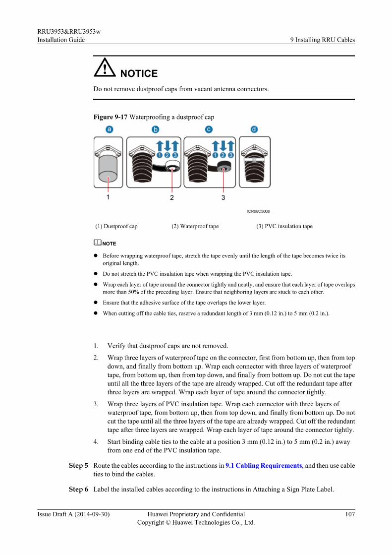
NOTICEDo not remove dustproof caps from vacant antenna connectors.
Figure 9-17 Waterproofing a dustproof cap
(1) Dustproof cap (2) Waterproof tape (3) PVC insulation tape
NOTE
l Before wrapping waterproof tape, stretch the tape evenly until the length of the tape becomes twice itsoriginal length.
l Do not stretch the PVC insulation tape when wrapping the PVC insulation tape.
l Wrap each layer of tape around the connector tightly and neatly, and ensure that each layer of tape overlapsmore than 50% of the preceding layer. Ensure that neighboring layers are stuck to each other.
l Ensure that the adhesive surface of the tape overlaps the lower layer.
l When cutting off the cable ties, reserve a redundant length of 3 mm (0.12 in.) to 5 mm (0.2 in.).
1. Verify that dustproof caps are not removed.
2. Wrap three layers of waterproof tape on the connector, first from bottom up, then from topdown, and finally from bottom up. Wrap each connector with three layers of waterprooftape, from bottom up, then from top down, and finally from bottom up. Do not cut the tapeuntil all the three layers of the tape are already wrapped. Cut off the redundant tape afterthree layers are wrapped. Wrap each layer of tape around the connector tightly.
3. Wrap three layers of PVC insulation tape. Wrap each connector with three layers ofwaterproof tape, from bottom up, then from top down, and finally from bottom up. Do notcut the tape until all the three layers of the tape are already wrapped. Cut off the redundanttape after three layers are wrapped. Wrap each layer of tape around the connector tightly.
4. Start binding cable ties to the cable at a position 3 mm (0.12 in.) to 5 mm (0.2 in.) awayfrom one end of the PVC insulation tape.
Step 5 Route the cables according to the instructions in 9.1 Cabling Requirements, and then use cableties to bind the cables.
Step 6 Label the installed cables according to the instructions in Attaching a Sign Plate Label.
RRU3953&RRU3953wInstallation Guide 9 Installing RRU Cables
Issue Draft A (2014-09-30) Huawei Proprietary and ConfidentialCopyright © Huawei Technologies Co., Ltd.
107

Step 7 Attach color-coding to the installed RF jumper according to the instructions in Attaching theColor Ring.
----End
9.7 Installing an RRU AISG Multi-Wire Cable and AISGExtension Cable
This section describes the procedures for installing an RRU AISG multi-wire cable and AISGextension cable.
Context
When the distance between an RRU and a Remote Control Unit (RCU) is longer than 5 m (16.4ft.), an AISG multi-wire cable is not long enough to connect the RRU and the RCU. In this case,an AISG extension cable is used to extend the AISG multi-wire cable.
Procedurel Install an AISG multi-wire cable that is not configured with an AISG extension cable.
1. Use an M3 flat-head screwdriver to loosen the screws on the dustproof cap on the RETport and remove the dustproof cap.
2. Link the waterproofed DB9 connector at one end the AISG multi-wire cable to theRET port on the RRU bottom, as shown in Figure 9-18.
Figure 9-18 Installing an RRU AISG multi-wire cable
RRU3953&RRU3953wInstallation Guide 9 Installing RRU Cables
Issue Draft A (2014-09-30) Huawei Proprietary and ConfidentialCopyright © Huawei Technologies Co., Ltd.
108

3. Use an M3 Phillips screwdriver to tighten the posts on both sides of the waterproofDB9 connector to 0.4 N·m (3.54 lbf·in.).
4. Connect the other end of the cable to the standard AISG male connector on the RCU.5. Route the cables according to the instructions in 9.1 Cabling Requirements, and then
use cable ties to bind the cables.6. Label the installed cables according to the instructions in Attaching an L-Shaped
Label.l Install an AISG multi-wire cable that is configured with an AISG extension cable.
1. Use an M3 flat-head screwdriver to loosen the screws on the dustproof cap on the RETport and remove the dustproof cap.
2. Link the waterproofed DB9 connector at one end of the AISG multi-wire cable to theRET port on the RRU bottom, and link the other end to the standard AISG maleconnector of the AISG extension cable, as shown in Figure 9-19.
Figure 9-19 Installing an RRU AISG multi-wire cable
3. Use an M3 Phillips screwdriver to tighten the posts on both sides of the waterproof
DB9 connector to 0.4 N·m (3.54 lbf·in.).4. Connect the other end of the AISG extension cable to the standard AISG male
connector on the RCU, as shown in Figure 9-20.
RRU3953&RRU3953wInstallation Guide 9 Installing RRU Cables
Issue Draft A (2014-09-30) Huawei Proprietary and ConfidentialCopyright © Huawei Technologies Co., Ltd.
109
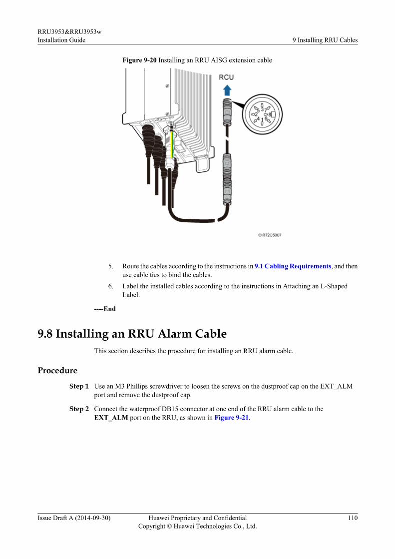
Figure 9-20 Installing an RRU AISG extension cable
5. Route the cables according to the instructions in 9.1 Cabling Requirements, and then
use cable ties to bind the cables.6. Label the installed cables according to the instructions in Attaching an L-Shaped
Label.
----End
9.8 Installing an RRU Alarm CableThis section describes the procedure for installing an RRU alarm cable.
Procedure
Step 1 Use an M3 Phillips screwdriver to loosen the screws on the dustproof cap on the EXT_ALMport and remove the dustproof cap.
Step 2 Connect the waterproof DB15 connector at one end of the RRU alarm cable to theEXT_ALM port on the RRU, as shown in Figure 9-21.
RRU3953&RRU3953wInstallation Guide 9 Installing RRU Cables
Issue Draft A (2014-09-30) Huawei Proprietary and ConfidentialCopyright © Huawei Technologies Co., Ltd.
110

Figure 9-21 Installing an RRU alarm cable
NOTE
Install the waterproof DB15 male connector on the RRU alarm cable with caution, preventing the pin assignmentfrom being damaged.
Step 3 Use an M3 Phillips screwdriver to tighten the posts on both sides of the waterproof DB15 maleconnector to 0.4 N·m (3.54 lbf·in.).
Step 4 Connect the eight cord end terminals at the other end to external alarm devices.
NOTE
Use insulating adhesive tapes to wrap cord end terminals that are not in use and fix them at a proper positionbased on the onsite situations. This prevents false alarm reporting and equipment damage due to contact ofexposed cables. Figure 9-22 shows the method for handling cord end terminals not in use.
Figure 9-22 Method for handling cord end terminals that are not in use
RRU3953&RRU3953wInstallation Guide 9 Installing RRU Cables
Issue Draft A (2014-09-30) Huawei Proprietary and ConfidentialCopyright © Huawei Technologies Co., Ltd.
111

Step 5 Route the cables according to the instructions in 9.1 Cabling Requirements, and then use cableties to bind the cables.
Step 6 Label the installed cables according to the instructions in Attaching an L-Shaped Label.
----End
9.9 Opening the Cover Plate of an RRU Cabling CavityThis section describes the procedure for opening the cover plate of an RRU cabling cavity.
Procedure
Step 1 Wear ESD gloves.
NOTICETake proper ESD protection measures, for example, wear ESD gloves, to prevent electrostaticdamage to the boards, modules, or electronic components.
Step 2 Use an M5 Phillips screwdriver to loosen the three screws on the cover plate of the RRU cablingcavity, and open the cover plate, as shown in Figure 9-23.
Figure 9-23 Opening the cover plate of the RRU cabling cavity
(1) Cover plate (2) Cabling cavity (3) Clip
(4) Cable trough for the power cable (5) Waterproof block (6) Cable trough for the fiber optical cable
RRU3953&RRU3953wInstallation Guide 9 Installing RRU Cables
Issue Draft A (2014-09-30) Huawei Proprietary and ConfidentialCopyright © Huawei Technologies Co., Ltd.
112
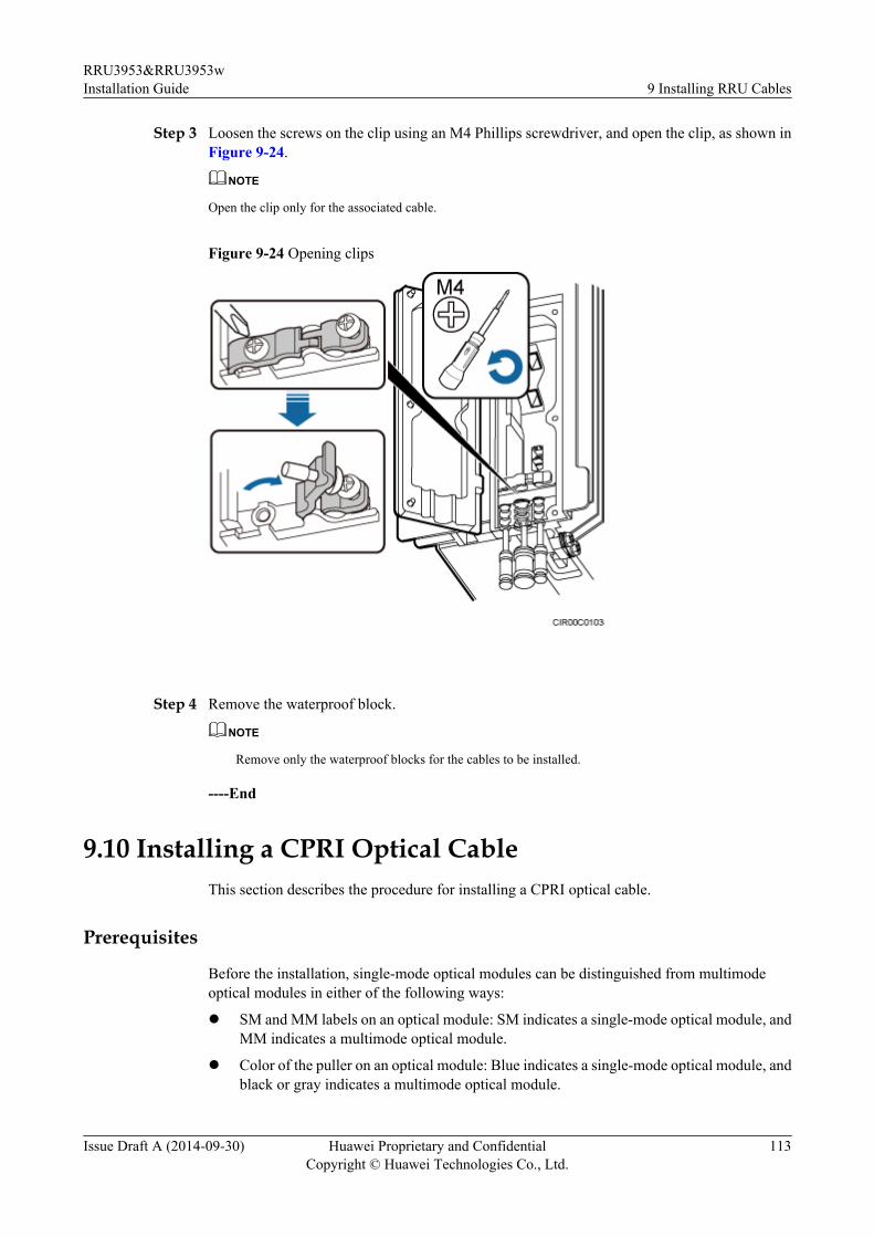
Step 3 Loosen the screws on the clip using an M4 Phillips screwdriver, and open the clip, as shown inFigure 9-24.
NOTE
Open the clip only for the associated cable.
Figure 9-24 Opening clips
Step 4 Remove the waterproof block.
NOTE
Remove only the waterproof blocks for the cables to be installed.
----End
9.10 Installing a CPRI Optical CableThis section describes the procedure for installing a CPRI optical cable.
Prerequisites
Before the installation, single-mode optical modules can be distinguished from multimodeoptical modules in either of the following ways:
l SM and MM labels on an optical module: SM indicates a single-mode optical module, andMM indicates a multimode optical module.
l Color of the puller on an optical module: Blue indicates a single-mode optical module, andblack or gray indicates a multimode optical module.
RRU3953&RRU3953wInstallation Guide 9 Installing RRU Cables
Issue Draft A (2014-09-30) Huawei Proprietary and ConfidentialCopyright © Huawei Technologies Co., Ltd.
113
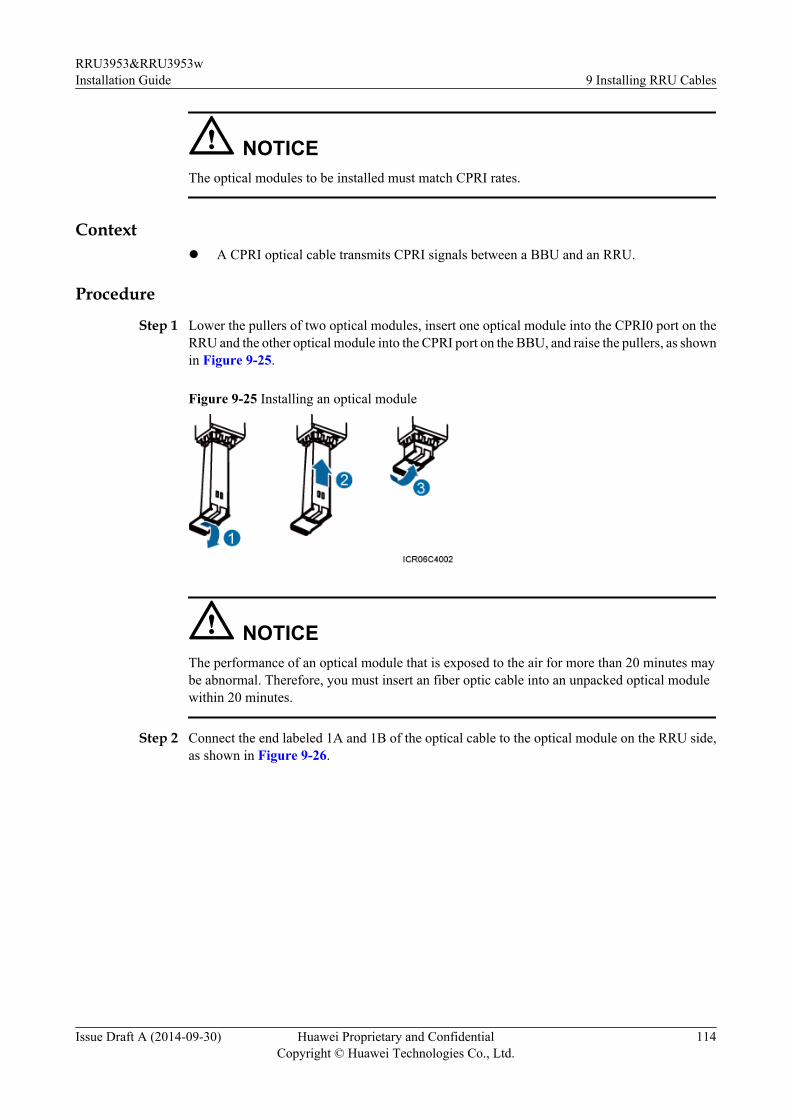
NOTICEThe optical modules to be installed must match CPRI rates.
Contextl A CPRI optical cable transmits CPRI signals between a BBU and an RRU.
Procedure
Step 1 Lower the pullers of two optical modules, insert one optical module into the CPRI0 port on theRRU and the other optical module into the CPRI port on the BBU, and raise the pullers, as shownin Figure 9-25.
Figure 9-25 Installing an optical module
NOTICEThe performance of an optical module that is exposed to the air for more than 20 minutes maybe abnormal. Therefore, you must insert an fiber optic cable into an unpacked optical modulewithin 20 minutes.
Step 2 Connect the end labeled 1A and 1B of the optical cable to the optical module on the RRU side,as shown in Figure 9-26.
RRU3953&RRU3953wInstallation Guide 9 Installing RRU Cables
Issue Draft A (2014-09-30) Huawei Proprietary and ConfidentialCopyright © Huawei Technologies Co., Ltd.
114

Figure 9-26 Installing a CPRI optical cable
NOTICETo avoid any damage to optical cables, the cables connected to the RRU must be installedaccording to the installation process. For details about the installation process, see 9.3 InstallingRRU Cables.
Step 3 Connect the end labeled 2A and 2B of the optical cable to the optical module on the BBU side.
Step 4 Route the cables according to the instructions in 9.1 Cabling Requirements, and then use cableties to bind the cables.
Step 5 Label the installed cables according to the instructions in Attaching an L-Shaped Label.
----End
9.11 Installing an RRU Power CableThis section describes the procedure for installing an RRU power cable.
Prerequisitesl A tool-less female connector (pressfit type) is added to the RRU power cable on the RRU
side. For details, see 12.1 Adding a Tool-Less Female Connector (Pressfit Type) to theRRU Power Cable on the RRU Side.
RRU3953&RRU3953wInstallation Guide 9 Installing RRU Cables
Issue Draft A (2014-09-30) Huawei Proprietary and ConfidentialCopyright © Huawei Technologies Co., Ltd.
115
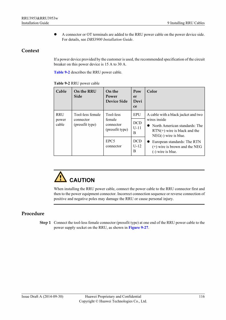
l A connector or OT terminals are added to the RRU power cable on the power device side.For details, see DBS3900 Installation Guide.
ContextIf a power device provided by the customer is used, the recommended specification of the circuitbreaker on this power device is 15 A to 30 A.
Table 9-2 describes the RRU power cable.
Table 9-2 RRU power cable
Cable On the RRUSide
On thePowerDevice Side
PowerDevice
Color
RRUpowercable
Tool-less femaleconnector(pressfit type)
Tool-lessfemaleconnector(pressfit type)
EPU A cable with a black jacket and twowires insidel North American standards: The
RTN(+) wire is black and theNEG(-) wire is blue.
l European standards: The RTN(+) wire is brown and the NEG(-) wire is blue.
DCDU-11B
EPC5connector
DCDU-12B
CAUTIONWhen installing the RRU power cable, connect the power cable to the RRU connector first andthen to the power equipment connector. Incorrect connection sequence or reverse connection ofpositive and negative poles may damage the RRU or cause personal injury.
Procedure
Step 1 Connect the tool-less female connector (pressfit type) at one end of the RRU power cable to thepower supply socket on the RRU, as shown in Figure 9-27.
RRU3953&RRU3953wInstallation Guide 9 Installing RRU Cables
Issue Draft A (2014-09-30) Huawei Proprietary and ConfidentialCopyright © Huawei Technologies Co., Ltd.
116
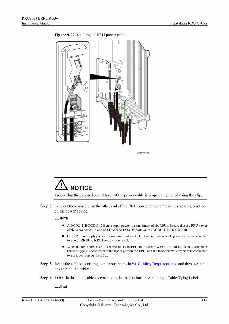
Figure 9-27 Installing an RRU power cable
NOTICEEnsure that the exposed shield layer of the power cable is properly tightened using the clip.
Step 2 Connect the connector at the other end of the RRU power cable to the corresponding positionon the power device.
NOTE
l A DCDU-11B/DCDU-12B can supply power to a maximum of six RRUs. Ensure that the RRU powercable is connected to one of LOAD0 to LOAD5 ports on the DCDU-11B/DCDU-12B.
l One EPU can supply power to a maximum of six RRUs. Ensure that the RRU power cable is connectedto one of RRU0 to RRU5 ports on the EPU.
l When the RRU power cable is connected to the EPU, the blue core wire in the tool-less female connector(pressfit type) is connected to the upper port on the EPU, and the black/brown core wire is connectedto the lower port on the EPU.
Step 3 Route the cables according to the instructions in 9.1 Cabling Requirements, and then use cableties to bind the cables.
Step 4 Label the installed cables according to the instructions in Attaching a Cable-Tying Label.
----End
RRU3953&RRU3953wInstallation Guide 9 Installing RRU Cables
Issue Draft A (2014-09-30) Huawei Proprietary and ConfidentialCopyright © Huawei Technologies Co., Ltd.
117

9.12 Closing the Cover Plate of an RRU Cabling CavityThis section describes the procedure for closing the cover plate of an RRU cabling cavity.
Procedure
Step 1 Close the clips for the installed cables. Use an M4 torque screwdriver to tighten the screws oneach clip to 1.4 N·m (12.39 lbf·in.), as shown in Figure 9-28.
NOTICEEnsure that the exposed shield layer of the power cable is properly tightened using the clip.
Figure 9-28 Closing clips
Step 2 Insert waterproof blocks into vacant cable troughs in the cabling cavity, as shown in Figure9-29.
NOTICEEnsure that cables and waterproof blocks are properly inserted into troughs.
RRU3953&RRU3953wInstallation Guide 9 Installing RRU Cables
Issue Draft A (2014-09-30) Huawei Proprietary and ConfidentialCopyright © Huawei Technologies Co., Ltd.
118

Figure 9-29 Correct placement of waterproof blocks
Step 3 Close the cover plate of the RRU cabling cavity. Use an M5 torque screwdriver to partiallytighten the screws on the cover plate in the sequence shown in Figure 9-30. Then tighten thescrews to 2 N·m (17.7 lbf·in.) in the same sequence.
Figure 9-30 Closing the cover plate of an RRU cabling cavity
Step 4 Take off the ESD gloves, and pack up all the tools.
----End
RRU3953&RRU3953wInstallation Guide 9 Installing RRU Cables
Issue Draft A (2014-09-30) Huawei Proprietary and ConfidentialCopyright © Huawei Technologies Co., Ltd.
119

10 Checking the RRU HardwareInstallation
After an RRU is installed, check the hardware installation.
Table 10-1 provides the checklist for the RRU hardware installation.
Table 10-1 Checklist for the RRU hardware installation
SN Item
1 The position for each device conforms to the engineering drawing and meets thespace requirement. Sufficient space is reserved for equipment maintenance.
2 The RRU is securely installed.
3 The cover plate is securely installed on the RRU cabling cavity.
4 Waterproof blocks are securely installed in vacant cable troughs of the RRU cablingcavity, and the cover plate for the cabling cavity is securely installed. In addition,vacant RF ports are covered with dustproof caps and the caps are tightened.
5 There are no connectors or joints on each power cable or PGND cable.
6 The terminals at two ends of each power cable or PGND cable are securely solderedor crimped.
7 None of power cables and PGND cables can be short-circuited or reverselyconnected. In addition, these cables are not damaged or broken.
8 Power cables and PGND cables are separately bound from other cables.
9 The protection grounding of the RRU and the surge protection grounding of thebuilding share one group of ground conductors.
10 The connectors of each signal cable are intact and securely linked, and these cablesare not damaged or broken.
11 Labels are correct, legible, and complete at both ends of each cable, feeder, andjumper.
RRU3953&RRU3953wInstallation Guide 10 Checking the RRU Hardware Installation
Issue Draft A (2014-09-30) Huawei Proprietary and ConfidentialCopyright © Huawei Technologies Co., Ltd.
120

11 Powering On an RRU
After all the devices are installed, check the power-on status of an RRU.
NOTICEAfter you unpack an RRU, you must power on it within 24 hours. If you power off the RRU formaintenance, you must restore power to the RRU within 24 hours.
Figure 11-1 shows the RRU power-on check process.
NOTE
For details about how to power on an RRU, see Powering On an RRU. For details about how to power offan RRU, see section "Powering-Off the RRU" in RRU Maintenance Guide.
RRU3953&RRU3953wInstallation Guide 11 Powering On an RRU
Issue Draft A (2014-09-30) Huawei Proprietary and ConfidentialCopyright © Huawei Technologies Co., Ltd.
121

Figure 11-1 RRU power-on check process
(a) The normal input voltage of an RRU is -48 V DC. The voltage of the external power supply should rangefrom -36 V DC to -57 V DC.
(b) The RUN indicator on the RRU is on for 1s and off for 1s. The ALM indicator is steady off.
RRU3953&RRU3953wInstallation Guide 11 Powering On an RRU
Issue Draft A (2014-09-30) Huawei Proprietary and ConfidentialCopyright © Huawei Technologies Co., Ltd.
122

12 Appendix
About This Chapter
This section describes the procedure for adding an easy power receptacle (pressfit type)connector.
12.1 Adding a Tool-Less Female Connector (Pressfit Type) to the RRU Power Cable on theRRU SideThis section describes the procedure for adding a tool-less female connector (pressfit type) tothe RRU power cable on the RRU side.
RRU3953&RRU3953wInstallation Guide 12 Appendix
Issue Draft A (2014-09-30) Huawei Proprietary and ConfidentialCopyright © Huawei Technologies Co., Ltd.
123

12.1 Adding a Tool-Less Female Connector (Pressfit Type)to the RRU Power Cable on the RRU Side
This section describes the procedure for adding a tool-less female connector (pressfit type) tothe RRU power cable on the RRU side.
Context
Figure 12-1 shows the cable diagram on labels.
Figure 12-1 Cable diagram on labels
(1) Cable diagram on labels
Procedure
Step 1 Determine the length of the power cable for different operations based on the labels, as shownin Figure 12-2.
Figure 12-2 Determining the length of the power cable
Step 2 Strip the specified length of the sheath off the power cable, as shown in Figure 12-3.
RRU3953&RRU3953wInstallation Guide 12 Appendix
Issue Draft A (2014-09-30) Huawei Proprietary and ConfidentialCopyright © Huawei Technologies Co., Ltd.
124
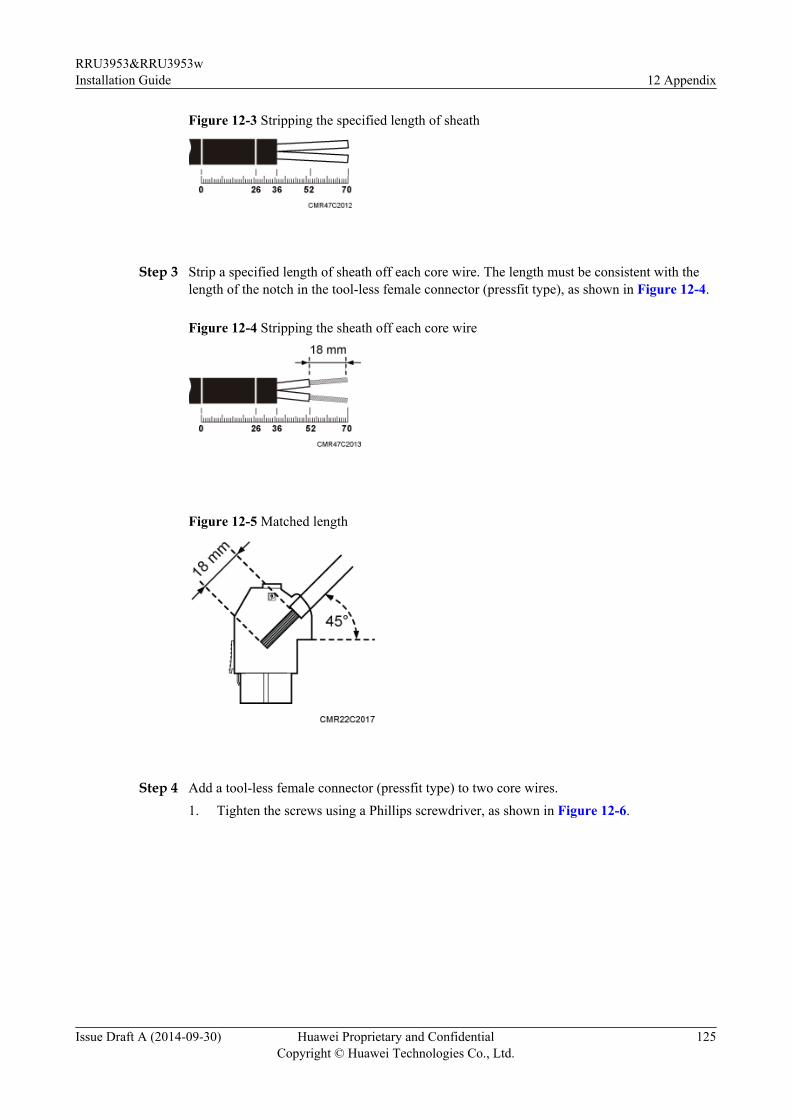
Figure 12-3 Stripping the specified length of sheath
Step 3 Strip a specified length of sheath off each core wire. The length must be consistent with thelength of the notch in the tool-less female connector (pressfit type), as shown in Figure 12-4.
Figure 12-4 Stripping the sheath off each core wire
Figure 12-5 Matched length
Step 4 Add a tool-less female connector (pressfit type) to two core wires.1. Tighten the screws using a Phillips screwdriver, as shown in Figure 12-6.
RRU3953&RRU3953wInstallation Guide 12 Appendix
Issue Draft A (2014-09-30) Huawei Proprietary and ConfidentialCopyright © Huawei Technologies Co., Ltd.
125

Figure 12-6 Tightening screws
2. Connect the blue core wire labeled NEG(-) to the - port and the black/brown core wire
labeled RTN(+) to the + port on the tool-less female connector (pressfit type), and thentighten the screws using a Phillips screwdriver, and then use a torque screwdriver to tightenthe M4 screws to 1.4 N·m (12.39 lbf·in.), as shown in Figure 12-7.
DANGERDo not reversely connect the positive and negative poles. Reverse connection of positiveand negative poles may result in equipment malfunctions or personal injury. Therefore,check the power cable connection before powering on the RRU.
Figure 12-7 Adding a tool-less female connector (pressfit type) to two core wires
Step 5 Strip the specified length of the sheath off the power cable to expose the intact shield layer, asshown in Figure 12-8.
RRU3953&RRU3953wInstallation Guide 12 Appendix
Issue Draft A (2014-09-30) Huawei Proprietary and ConfidentialCopyright © Huawei Technologies Co., Ltd.
126

Figure 12-8 Stripping the sheath off the power cable
NOTICEEach core wire is exposed outside the tool-less female connector (pressfit type) for 1.5 mm(0.059 [in.]), as shown in Figure 12-9.
Figure 12-9 Inserting core wires into the tool-less female connector (pressfit type)
----End
RRU3953&RRU3953wInstallation Guide 12 Appendix
Issue Draft A (2014-09-30) Huawei Proprietary and ConfidentialCopyright © Huawei Technologies Co., Ltd.
127