INSTALLATION GUIDE - DMP · INSTALLATION GUIDE FCC NOTICE This ... Reorient the receiving antenna...
24
INSTALLATION GUIDE XR150FC/XR550FC SERIES PANEL
Transcript of INSTALLATION GUIDE - DMP · INSTALLATION GUIDE FCC NOTICE This ... Reorient the receiving antenna...

InstallatIon GuIde
XR150fc/XR550fc seRIes Panel

MODEL XR150FC/XR550FC SERIES PANELINSTALLATION GUIDE
FCC NOTICE
This equipment generates and uses radio frequency energy and, if not installed and used properly in strict accordance with the manufacturer’s instructions, may cause interference with radio and television reception. It has been type tested and found to comply with the limits for a Class A computing device in accordance with the specification in Subpart J of Part 15 of FCC Rules, which are designed to provide reasonable protection against such interference in a residential installation. If this equipment does cause interference to radio or television reception, which can be determined by turning the equipment off and on, the installer is encouraged to try to correct the interference by one or more of the following measures:
Reorient the receiving antennaRelocate the computer with respect to the receiverMove the computer away from the receiverPlug the computer into a different outlet so that computer and receiver are on different branch circuits
If necessary, the installer should consult the dealer or an experienced radio/television technician for additional suggestions. The installer may find the following booklet, prepared by the Federal Communications Commission, helpful:
“How to identify and Resolve Radio-TV Interference Problems.”
This booklet is available from the U.S. Government Printing Office, Washington D.C. 20402
Stock No. 004-000-00345-4
© 2013 Digital Monitoring Products, Inc.
Information furnished by DMP is believed to be accurate and reliable.This information is subject to change without notice.

XR150FC/XR550FC Series Installation Guide Digital Monitoring Productsi
Table of ConTenTs
Product Specifications Summary1.1 Power Supply .........................................................................11.2 Communication ......................................................................11.3 Panel Zones ...........................................................................11.4 Keypad Bus ............................................................................11.5 LX-Bus™ ................................................................................11.6 Outputs .................................................................................1
Panel Features2.1 Description .............................................................................22.2 Zone Expansion ......................................................................22.3 Output Expansion ...................................................................22.4 Caution Notes ........................................................................22.5 Compliance Instructions ..........................................................2
System Components3.1 Wiring Diagram ......................................................................33.2 Lightning Protection ................................................................33.3 Network Protection .................................................................33.4 Accessory Devices ..................................................................43.4 Accessory Devices (continued) .................................................5
Installation4.1 Mounting the Enclosure ...........................................................64.2 Fire Command Center LCD Keyboard ........................................64.3 Connection .............................................................................64.4 Mounting Keypads and Zone Expansion Modules .......................7
Primary Power Supply5.1 Transformers and AC Power Connection ...................................8
Secondary Power Supply6.1 Battery Terminals 3 and 4 .......................................................96.2 Earth Ground (GND) ...............................................................96.3 Battery Only Restart ...............................................................96.4 Battery Replacement Period.....................................................96.5 Discharge/Recharge ................................................................96.6 Battery Supervision .................................................................96.7 Battery Cutoff .........................................................................96.8 Power Requirements .............................................................106.9 Standby Battery Selection .....................................................12
Bell Output7.1 Terminals 5 and 6 .................................................................13
Keypad Bus8.1 Description ...........................................................................138.2 Terminal 7 - RED ..................................................................138.3 Terminal 8 - YELLOW ............................................................138.4 Terminal 9 - GREEN ..............................................................138.5 Terminal 10 - BLACK .............................................................138.6 Programming (PROG) Connection ..........................................138.7 OVC LED(s) ..........................................................................13
Smoke and Glassbreak Detector Output9.1 Terminals 11 and 12 .............................................................139.2 Current Rating ......................................................................13
Protection Zones10.1 Terminals 13–24 ...................................................................1410.2 Operational Parameters .........................................................1410.3 Zone Response Time .............................................................1410.4 Keyswitch Arming Zone .........................................................14

Digital Monitoring Products XR150FC/XR550FC Series Installation Guideii
Table of ConTenTs
Powered Zones for 2-Wire Smoke Detectors11.1 Terminals 25–26 and 27–28 ..................................................14
Dry Contact Relay Outputs12.1 Description ...........................................................................1512.2 Contact Rating .....................................................................1512.3 Model 431 Output Harness Wiring ..........................................15
Annunciator Outputs13.1 Description ...........................................................................1513.2 Model 300 Harness Wiring .....................................................1513.3 Model 860 Relay Module .......................................................15
Wireless Bus Expansion14.1 Description ...........................................................................1614.2 Wireless Bus LEDs ................................................................16
LX-Bus Expansion15.1 LX-Bus Headers ....................................................................1615.2 LX-Bus LEDs .........................................................................1615.3 OVC LEDs ............................................................................16
ETHERNET Connector16.1 Description ...........................................................................1616.2 Ethernet LEDs ......................................................................1616.3 Network Transient Suppression ..............................................16
PHONE LINE RJ Connector17.1 Description ...........................................................................1717.2 893A OR 277 Connector ........................................................1717.3 Notification ..........................................................................1717.4 Phone Line Monitor ...............................................................1717.5 FCC Registration ...................................................................17
RESET and TAMPER Headers18.1 RESET Header .....................................................................1818.2 TAMPER Header ...................................................................18
Certifications

XR150FC/XR550FC Series Installation Guide Digital Monitoring Products1
IntroductIon
Product Specifications Summary
1.1 Power SupplyTransformer Input: Primary input: 120 Vac, 60 Hz, Secondary output: 16 Vac 56 VAStandby Battery: 12 Vdc, 1.0 Amps Max. charging currentAuxiliary: 12 Vdc output at .5 Amp Max*Bell Output: 12 Vdc at .7 Amp Max*
Note: The combined Auxiliary and Bell outputs total cannot exceed 1.2 Amps with a 56 VA Transformer.All circuits are inherent Power Limited except the red battery wire and AC terminal.* For Commercial Fire installations, see the Compliance Listing Guide LT-1330.
1.2 Communication• Built-in network communication to DMP Model SCS-1R and SCS-VR Receivers• Built-in dialer communication to DMP Model SCS-1R Receivers• Optional cellular communication to DMP Model SCS-1R and SCS-VR Receivers• Built-in Contact ID communication to DMP Model SCS-1R Receivers• Optional 893A Dual Phone Line Module with phone line supervision• Can operate as a local panel
1.3 Panel ZonesEight 1k Ohm EOL burglary zones (zones 1 to 8)Two 3.3k Ohm EOL powered zone with reset (zones 9 and 10)
1.4 Keypad BusYou can connect the following supervised keypads and expansion modules to the keypad bus:
• Alphanumeric keypads • Sixteen-, eight-, four- and/or single-zone expansion modules• Single-zone detectors • Access control modules
1.5 LX-Bus™You can connect the following devices to the LX-Bus™ connections provided on the panel. See Accessory Devices section 3.4.
• Sixteen-, eight-, four- and/or single-zone expansion modules • Graphic annunciator modules• Model 521LX or 521LXT Smoke Detectors with CleanMe • Relay output expansion modules• Model 2W-BLX or 2WT-BLX Smoke Detectors
1.6 OutputsThe XR150FC/XR550FC Series provide two Single Pole, Double Throw (SPDT) relay outputs which require the installation of two Model 305 relays, each rated 1 Amp at 30 Vdc resistive (power limited sources only). A Model 431 Output Harness is required to use these outputs.The XR150FC/XR550FC Series panels also provide four open collector outputs rated for 50mA each. The open collector outputs provide ground connection for a positive voltage source. A Model 300 Output Harness is required to use these outputs.

Digital Monitoring Products XR150FC/XR550FC Series Installation Guide2
IntroductIon
Panel Features2.1 DescriptionThe DMP XR150FC/XR550FC Series system is made up of an alarm panel with a built-in communicator, an enclosure, battery, one 16 Vac transformer, and keypads. Each panel is a versatile 12 Vdc, combined access control, burglary, and fire communicator panel with a built in LCD Fire Command Center keyboard with membrane keyswitch. A complete system can provide:
• 574 or 142 programmable inputs and outputs for commercial and industrial fire alarm service• Eight on-board grounded burglary zones• Two on-board 12 Vdc Class B powered zones
The powered zones have a reset capability to provide for 2-wire smoke detectors, relays, or other latching devices. Connect a 12 or 24 Vdc regulated, power limited power supply listed for Fire Protective Signaling Systems to distribute notification appliance power between Model 865, 866 or 867 NAC outputs. Addressable smoke detectors and input modules round out the XR150FC/XR550FC Series to deliver a truly flexible and expansive fire detection and notification system. The Fire Alarm Control Panel is shipped pre-wired in a red metal enclosure.
2.2 Zone ExpansionUp to 574 additional zones are available on the XR150FC/XR550FC Series using DMP LCD keypad remote zone capability and zone expansion modules. The panel keypad data bus supports up to fifteen supervised device addresses with each address supporting up to four programmable expansion zones.Up to 500 zones are available using the on board LX-Bus™ connections, and any combination of single, four, eight, or sixteen-zone expansion modules and single-zone LX-Bus™ detectors.Note: Do not use shielded or twisted pair wiring for LX-Bus or Keypad Bus circuits.
2.3 Output ExpansionIn addition to the two SPDT relays and four programmable open collector outputs on the panel, you can also connect up to 25 programmable Model 716 Output Expansion Modules to each LX-Bus. These modules can provide an additional 500 or 100 programmable SPDT relays.The XR150FC/XR550FC Series provides 100 Output Schedules you can use for programming the 716 to perform a variety of annunciation and control functions. You can also assign the 716 outputs to any panel Output Options such as Fire Alarm, Communication Fail, or Phone Trouble Outputs. Refer to the 716 Installation Guide (LT-0183).The LX-Bus™ also supports the Model 717 Graphic Annunciator Module. Each 717 module supplies 20 switched ground outputs that follow the state of their assigned zones.Note: The 717 supports the first eight Keypad Bus addresses. To follow Keypad Bus addresses nine through 16, install
multiple 716 modules. Refer to the 717 Installation Guide (LT-0235) and 716 Installation Guide (LT-0183).
2.4 Caution NotesThroughout this guide you will see caution notes containing information you need to know when installing the panel. These cautions are indicated with a yield sign. Whenever you see a caution note, make sure you completely read and understand its information. Failing to follow the caution note can cause damage to the equipment or improper operation of one or more components in the system. See the example shown below.
Always ground the panel before applying power to any devices: The panel must be properly grounded before connecting any devices or applying power to the panel. Proper grounding protects against Electrostatic Discharge (ESD) that can damage system components.
2.5 Compliance InstructionsFor applications that must conform to a local authorities installation standard or a National Recognized Testing Laboratory certificated system, please see the Compliance Listing Guide (LT-1330) for additional instructions.

XR150FC/XR550FC Series Installation Guide Digital Monitoring Products3
IntroductIon
System Components3.1 Wiring DiagramThe diagram shows some of the accessory modules you can connect for use in various applications. A brief description of each module follows in section 3.4.
AC
1 2 3 4 5 6 7 8 10 11 12 13 14 15 16 17 18 199 20 21 22 23 24 25 26 27 28
+B BELLGND SMK GNDRED YEL GRN BLK Z1 Z2 Z3 Z4 Z5 Z6 Z7 Z8 Z9+ Z9– Z10+Z10–AC –B GND GND GNDGND
XR550FC SeriesPanel
¼"
SmokeDetector
3.3k Ohm 3.3k Ohm 3.3k Ohm 3.3k Ohm
1k Ohm
AC Wiring must be in conduit and exit out the left side of the enclosure. Wiring on terminals 5 through 22 must exit right and maintain 1/4" separation from the AC and battery positive wiring.
Form C Relays (J2)Output Color Code–Model 431 HarnessOutput 2 N/O Orange/WhiteOutput 2 Com White/GrayOutput 2 N/C Violet/WhiteOutput 1 N/O OrangeOutput 1 Com GrayOutput 1 N/C Violet
Annunciator Outputs (J11)Output Color CodeOutput 3 RedOutput 4 YellowOutput 5 GreenOutput 6 Black
FrontTamper
RearTamper
s
REDBLACK
Bell
Zone
1
Zone
2
Zone
3
Zone
4
Zone
5
Zone
6
Zone
7
Zone
8
3.3kOhm
Resistor
3.3kOhm
Resistor
Zone Expander Model 715
7mA @ 12 VDCModels 715-8, 715-16
20mA @ 12 VDC
1k Ohm
s = Supervised Circuit
Zone9
Zone10
22 g
auge
min
imum
22 g
auge
min
imum
22 g
auge
min
imum
22 g
auge
min
imum
RED
YELL
OW
GREE
N
BLAC
K
1k Ohm 1k Ohm 1k Ohm
Zone Expander Model 714
7mA @ 12 VDCModels 714-8, 714-16
20mA @ 12 VDC
REDYELLOWGREENBLACK
RED
s
ss
s s s s s
ss
S S S S S S S S
S S S S
1kOhm
SS
1kOhm
SS
1kOhm
SS
1kOhm
SS
1kOhm
SS
1kOhm
SS
1kOhm
SS
1kOhm
SS
S SS SS SS S
1k Ohm
Zone Expander (up to 8 zones)
Model 712-819mA @ 12
VDC
S S
ZoneExpanderModel 7117mA @ 12
VDC
1.5k Ohm
s
Ground
s
J3PHONE LINE
J16
RESET
J4TAMPER
BatteryStart
PowerLED
Activity LED
J1ETHERNET
OUTPUTS 3-6
J11
J10K6 K7
OUTPUT 1 OUTPUT 2
OU
T1O
UT2
J2
Link LED
J24
CELL MODULE
J18
LOADJ7
s
s
PROGJ8 J14 J9 J15
J13
J17 J19
J6
LXK
DMP Transformer16 VAC 56 VAClass 2 Wire-in.
Secondary Power Supply1.0 Amps Max. charging current. Use only 12 VDC rechargeable batteries. DMP Models 364, 365, 366, 368, or 369. Replace batteries every 3 to 5 years.
Bell12 VDC nominalMinimum cutoff time is 5 minutes..7 Amp Max
KeypadsModel 630F60mA at 8 to 14.5 VDC
Bell cutoff time range is 5 to 99 minutes marchtimeand non-coded.
All circuits are inherent Power Limited except the red battery wire and AC terminal.
NFPA 72This equipment should be installed in accordance with Chapter 11 of the National Fire Alarm Code, ANSI/NFPA 72-2002, (National Fire Protection Association, Batterymarch Park, Quincy, MA 02269). Printed information describing proper installation, operation, testing, maintenance, evacuation planning, and repair service is to be provided with this equipment.
Use UL Listed PowerSupervision Relayrated at 12 VDC.
POWER
TROUBLE
ALARM
COMMAND
1 2 3 4
5 6 7 8
9 0
ABC DEF GHI JKL
MNO PQR STU VWX
YX
ENABLE
SILENCE
RESET
TEST
DRILL
Fire Command Center
WARNING: Incorrect connections may cause damage to the unit.
CAUTION: DO NOT USE LOOPED WIRE UNDER TERMINALS. BREAK WIRE RUN TOPROVIDE SUPERVISION OF CONNECTIONS.
Auxiliary PowerTotal current combined from terminals 7, 11, 25, 27, and
LX500-LX900.5 Amp Max
Listed Resistors1.0k Ohm - DMP Model 3113.3k Ohm - DMP Model 30910K Ohm - DMP Model 308
Cold Water Pipe Earth Ground
Heat detectors, pull stations, or any other contact devices listed for Fire Protective Signaling can be connected to zones 9 and 10. Zones 9 and 10 and Model 715 compatibilityidentifier: A
Maximum operatingrange: 9.8 VDC to 14.0 VDC.Class B (Style A).
Zones 9, 10, and all expanded zones are suitable for Class B (as applicable for the initiating and signaling line circuits per ANSI/UL 864 Table 48.2 or 48.3). Installation limits under local Authority Having Jurisdiction (AHJ). Using verification delays on zones 9 and 10 is optional. Use the delays marked on the smoke detectors or the smoke detector installation wiring diagram.
WARNINGTHIS UNIT MAY BE PROGRAMMED TO USE AN ALARM VERIFICATIONFEATURE THAT RESULTS IN DELAY OF THE SYSTEM ALARM SIGNAL FROM THE INDICATED CIRCUITS. THE TOTAL DELAY (CONTROL UNIT PLUS SMOKE DETECTORS) SHALL NOT EXCEED 60 SECONDS. NO OTHERSMOKE DETECTOR SHALL BE CONNECTED TO THESE CIRCUITS UNLESSAPPROVED BY THE LOCAL AUTHORITY HAVING JURISDICTION (AHJ).
VerificationZones
______
Control UnitDelay
13.6 sec.
SmokeModel
______
DetectorDelay
____sec.
Figure 1: XR150FC/XR550FC Series Wiring Diagram
3.2 Lightning ProtectionMetal Oxide Varistors and Transient Voltage Suppressors help protect against voltage surges on XR150FC/XR550FC Series input and output circuits. Additional surge protection is available by installing the DMP 370 or 370RJ Lightning Suppressors.3.3 Network ProtectionThe Model 270 Network Transient Suppression Module protects the XR150FC/XR550FC panel from surges on the ETHERNET port.

Digital Monitoring Products XR150FC/XR550FC Series Installation Guide4
IntroductIon
3.4 Accessory Devices
Interface Adaptor and Interface Cards 263C CDMA Cellular Communicator Allows you to connect the XR150FC/XR550FC Series to any compatible CDMA/SMS network. 263H HSPA+ Cellular
CommunicatorAllows you to connect the XR150FC/XR550FC Series to any compatible HSPA/SMS network.
Expansion Modules 270 Network Transient Suppression Module
Provides transient surge protection for the ETHERNET Connector.
277 Trouble Sounder Provides local sounder for monitoring of panel operations and loss of Keypad Bus.710 Bus Splitter/Repeater Increase keypad/LX-Bus™ wiring distance to 2500 feet.711 Single Point Zone Expanders Provides one Class B zone for connecting burglary devices.714, 714-8, 714-16 Zone Expanders Provides Class B zones for connecting burglary and non-powered fire devices.712-8 Zone Expander Provides Class B zones for connecting burglary devices.715, 715-8, 715-16 Zone Expanders Provides 12 Vdc Class B powered zones for connecting smoke detectors, glassbreak
detectors, and other 2- or 4-wire devices.716 Output Expander Provides four Form C relays (SPDT) and four switched grounds (open collector) for use in a
variety of remote annunciation and control applications for use on the LX-Bus only.717 Graphic Annunciator Module Provides 20 zone following annunciator outputs (open collector) for use in a variety of
remote annunciation and control applications for use on the LX-Bus only.734, 734N Wiegand Interface Modules
Provides system codeless entry, and arming and disarming using access control readers.
DMP Two-Way Wireless Devices1100X/1100XH Wireless Receiver Supports up to 500 devices in residential or commercial wireless operation. 1100R Repeater Provides additional range for wireless devices.1101 Universal Transmitter Provides both internal and external contacts that may be used at the same time to yield
two individual reporting zones from one wireless transmitter.1102 Universal Transmitter Provides an external contact.1103 Universal Transmitter Provides both and internal and external contacts that may be used at the same time to
yield two individual reporting zones from one wireless transmitter. Requires EOL resistor for external contact. Provides Disarm/Disable functionality.
1105 Universal Transmitter Provides both internal and external contacts that may be used at the same time to yield two individual reporting zones from one wireless transmitter.
1125 PIR Motion Detector Provides multiple lens configurations, dual coverage area selection, and sensitivity adjustments.
1127C/1127W PIR Motion Detector Wall mount motion detector with panel programmable sensitivity and Disarm/Disable functionality.
1142BC Two-button Hold-up Belt Clip Transmitter
Provides two-button hold-up operation with a belt clip.
1142 Two-button Hold-up Transmitter
Provides permanently mounted under-the-counter two-button hold-up operation.
1161 Residential Smoke Detector Residential smoke detector with sounder.1162 Residential Smoke/Heat Detector
Residential smoke/heat detector with sounder and fixed rate-of-rise heat detector.

XR150FC/XR550FC Series Installation Guide Digital Monitoring Products5
IntroductIon
3.4 Accessory Devices (continued)DMP Two-Way Wireless Devices (continued)1165 Commercial Smoke Detector
Commercial smoke detector.
1165H Commercial Smoke/Heat Detector
Commercial smoke/heat detector with fixed rate-of-rise heat detector.
1165HS Commercial Smoke/Heat Detector and Sounder
Commercial smoke/heat detector with fixed rate-of-rise heat detector and sounder.
1181 PIV Commercial Post Indicator Valve (PIV).1182 OS&Y Commercial Outside Screw and Yoke Valve (OS&Y).1183-135F Heat Detector Fixed temperature heat detector.1183-135R Heat Detector Fixed temperature and rate-of-rise heat detector.1184 Carbon Monoxide Detector Carbon Monoxide Detector.
Indicating and Initiating Devices860 Relay Module Provides up to four Form C (SPDT) dry relay contacts that are programmable and controlled
from DMP panel annunciator outputs.865 Supervised Style W or X Notification Circuit Module
Provides supervised alarm current when using the XR150FC/XR550FC Series panel bell output and up to 5 Amps at 12 or 24 Vdc when using a listed auxiliary power supply. The 865 can supervise 2-wire or 4-wire style circuits for opens and shorts with individual LED annunciation.
866 Style W Notification Circuit Module
Provides supervised alarm current using the XR150FC/XR550FC Series panel bell output and up to 5 Amps at 12 or 24 Vdc when using a listed auxiliary power supply. The 866 can supervise 2-wire Style W circuits for opens and shorts.
867 Style W LX-Bus Notification Circuit Module
Provides supervised alarm current using the XR150FC/XR550FC Series panel bell output and up to 5 Amps at 12 or 24 Vdc when using a listed auxiliary power supply. The 867 connects to the XR150FC/XR550FC Series panel LX-Bus™ and provides one 2-wire Style W notification circuit for ground faults, open and short conditions. Individual Bell Relay addresses Bell Ring styles.
869 Dual Class A Style D Initiating Module
Provides two Class A, Style D, 4-wire initiating zones for connecting waterflow switches and other non-powered fire and burglary devices.
Accessory Modules and Keypads893A Dual Phone Line Module Allows you to supervise two standard phone lines connected to an XR150FC/XR550FC Series
panel. The 893A module monitors the main and backup phone lines for a sustained voltage drop and alerts users when the phone line is bad.
LCD keypads Allows you to control the panel from various remote locations. Connect up to fifteen supervised Model 630F Remote Fire Command Center, 7060, 7063, 7070, 7073, 7160, 7163, 7170, 7173 Thinline™ keypads, 7060A, 7063A, 7070A, 7073A Aqualite™ keypads, or 7872, 7873 Graphic Touchscreen keypads to the keypad bus using terminals 7, 8, 9, and 10.
Addressable Smoke Detectors521LX, 521LXT Single-zone, addressable conventional smoke, smoke/heat detectors that connect to the
LX-Bus. Includes remote maintenance reporting, drift compensation, and multi-criteria detection.
2W-BLX, 2WT-BLX Single-zone, addressable conventional smoke, smoke/heat detectors that connect to the LX-Bus. Includes drift compensation.

Digital Monitoring Products XR150FC/XR550FC Series Installation Guide6
IntroductIon
Installation4.1 Mounting the EnclosureThe metal enclosure for the XR150FC/XR550FC Series must be mounted using screws in the four mounting holes shown in Figure 2. Mount the enclosure in a secure, dry place to protect the panel from damage due to tampering or the elements. It is not necessary to remove the XR150FC/XR550FC Series PCB when installing the enclosure.The enclosure dimensions are 13.44” tall, 17.1” wide, by 4.8” deep.
Note: When using the XR150FC/XR550FC Series panel for listed applications, use the Model 350, 349, 341, or 352S enclosure for standby batteries.
Enclosure Mounting Holes
3-HolePattern forAccessoryModules
Dual 1 3/4" and 1 3/8" Conduit Knockouts
Battery shelf holds up to two batteries. Maintain minimum spacing of 1/4” between the batteries and any modules mounted in enclosure.
XR550FC Panel
Figure 2: XR150FC/XR550FC Series enclosure
4.2 Fire Command Center LCD KeyboardA Fire Command Center LCD Keyboard has been factory installed on the XR150FC/XR550FC enclosure door. A keyswitch has also been installed and pre-wired to the left of the keyboard. The user can turn the keyswitch to enable the four function keys without opening the enclosure door.
POWER
TROUBLE
ALARM
COMMAND
1 2 3 4
5 6 7 8
9 0
ABC DEF GHI JKL
MNO PQR STU VWX
YX
ENABLE
SILENCE
RESET
TEST
DRILL
Fire Command Center
Figure 3: Fire Command Center LCD and Keyboard
4.3 ConnectionThe display and keyboard are factory pre-wired to the XR150FC/XR550FC PROG header. For standby battery calculations, the display draws 92mA of current in normal standby or alarm condition. See Panel Standby Battery Calculations. The keyswitch is pre-wired to the membrane keyboard.

XR150FC/XR550FC Series Installation Guide Digital Monitoring Products7
InstallatIon
4.4 Mounting Keypads and Zone Expansion ModulesDMP LCD keypads have removable covers that allow you to easily mount the keypad to a wall or other flat surface using the screw holes on each corner of the base. Before mounting the base, connect the keypad wire harness leads to the keypad cable from the panel and to any device wiring run to that location. Then attach the harness to the pin connector on the PC board, mount the base, and install the keypad cover making sure all of the keys extend through their respective holes.
For mounting keypads on solid walls, or for applications where conduit is required, use the Model 695 1-1/2” deep or the Model 696 1/2” deep backboxes.
The DMP 711, 712-8, 714, 715, 716, and 717 modules are each contained in molded plastic housings with removable covers. The base provides you with mounting holes for installing the unit to a wall, switch plate, or other surface.
4.5 Connecting LX-Bus and Keypad Bus DevicesConnections for LX-Bus and Keypads are provided through the PROG, LX500, LX600, LX700, LX800, LX900, and XBUS 4-pin headers. Several factors determine the DMP LX-Bus™ and keypad bus performance characteristics: the wire length and gauge used, the number of devices connected, and the voltage at each device. When planning an LX-Bus™ and keypad bus installation, keep in mind the following information:
1. DMP recommends using 18 or 22-gauge unshielded wire for all keypad and LX-Bus circuits. Do not use twisted pair or shielded wire for LX-Bus and keypad bus data circuits.
2. On keypad bus circuits, to maintain auxiliary power integrity when using 22-gauge wire do not exceed 500 feet. When using 18-gauge wire do not exceed 1,000 feet. To increase the wire length or to add devices, install an additional power supply that is listed for Fire Protective Signaling, power limited, and regulated (12 Vdc nominal) with battery backup. Note: Each panel allows a specific number of supervised keypads. Add additional keypads in the unsupervised mode. Refer to the panel installation guide for the specific number of supervised keypads allowed.
3. Maximum distance for any one bus circuit (length of wire) is 2,500 feet regardless of the wire gauge. This distance can be in the form of one long wire run or multiple branches with all wiring totaling no more than 2,500 feet. As wire distance from the panel increases, DC voltage on the wire decreases. Maximum number of LX-Bus devices on the first 2,500 foot circuit is 40 devices.
4. Maximum voltage drop between the panel (or auxiliary power supply) and any device is 2.0 Vdc. If the voltage at any device is less than the required level, add an auxiliary power supply at the end of the circuit. When voltage is too low, the devices cannot operate properly.
For additional information refer to the LX-Bus/Keypad Bus Wiring Application Note (LT-2031).

Digital Monitoring Products XR150FC/XR550FC Series Installation Guide8
InstallatIon
Primary Power Supply
5.1 Transformers and AC Power ConnectionThe AC connection should be completed by a licensed electrician.
Never share the Fire Alarm Control Panel circuit with any other equipment.
The XR150FC/XR550FC panel comes supplied with a 16 Vac 56 VA transformer. The 16 Vac transformer must be wired to a dedicated unswitched 120 Vac 60 Hz circuit with at least .87A available.
Always ground the panel before applying power to any devices! Use 18 AWG or larger for all power connections. The panel must be properly grounded before connecting any devices or applying power. Proper grounding protects against Electrostatic Discharge (ESD) that can damage system components.
The 16 VAC transformer must be wired to a dedicated unswitched 120 VAC 60 Hz circuit with at least .87A available
Install cover over screw terminals after completing connection.
WHITE
BLACK
Ground WireConnectedto Enclosure
GREEN/YELLOW
GND
SS
56 VATransformer
OVC
AC
1 2 3 4 5 6 7 8 10 11 12 13 14 15 16 17 18 199 20 21 22 23 24 25 26 27 28
+B BELLGND SMK GNDRED YEL GRN BLK Z1 Z2 Z3 Z4 Z5 Z6 Z7 Z8 Z9+ Z9– Z10+Z10–AC –B GND GND GNDGND
K6 K7
Output 1 Output 2
J3Phone Line
J10BatteryStart
PowerLED
J8PROG
J4Tamper
J16Reset
Out
1O
ut2Outputs 3-6
J113456
J2
Figure 4: 56 VA Transformer Wiring

XR150FC/XR550FC Series Installation Guide Digital Monitoring Products9
InstallatIon
Secondary Power Supply
6.1 Battery Terminals 3 and 4Connect the black battery lead to the negative battery terminal. The negative terminal connects to the enclosure ground internally through the XR150FC/XR550FC Series circuit board. Connect the red battery lead to the battery positive terminal. Observe polarity when connecting the battery.
You can add a second battery in parallel using the DMP Model 318 Dual Battery Harness.
DMP requires each battery be separated by a PTC in the battery harness wiring to protect each battery from a reversal or short within the circuit. See Figure 5.
For listed installations, batteries can be installed in a DMP Model 341, 349, 350 or 352S enclosure and all wiring shall run through conduit. The enclosure shall be installed to the left of the XR150FC/XR550FC Series enclosure to ensure Battery and AC wire separation.
Use sealed lead-acid batteries only: Use the DMP Model 364 (12 Vdc 1.3 Ah), 365 (12 Vdc 9 Ah), Model 366 (12 Vdc 18 Ah), Model 368 (12 Vdc 5.0 Ah), or Model 369 (12 Vdc 7 Ah) sealed lead-acid rechargeable battery. Batteries supplied by DMP have been tested to ensure proper charging with DMP products.
GEL CELL BATTERIES CANNOT BE USED WITH THE XR150FC/XR550FC SERIES PANEL.
6.2 Earth Ground (GND)To provide proper transient suppression, XR150FC/XR550FC Series panel terminal 4 must be connected to earth ground using 14 gauge or larger wire. DMP recommends connecting to a cold water pipe, ground rod, or building ground only. Do not connect to an electrical ground or conduit, sprinkler or gas pipes, or to a telephone company ground.
6.3 Battery Only RestartWhen powering up the XR150FC/XR550FC Series panel without AC power, briefly short across the battery start pads to pull in the battery cutoff relay. The leads need a momentary short only. Once the relay has pulled in, the battery voltage holds it in that condition. If the XR150FC/XR550FC Series panel is powered up with an AC transformer, the battery cutoff relay is pulled in automatically. For more information refer to Figure 1.
6.4 Battery Replacement PeriodDMP recommends replacing the battery every 3 to 5 years under normal use.
6.5 Discharge/RechargeThe XR150FC/XR550FC Series battery charging circuit float charges at 13.9 Vdc at a maximum current of 1.0 Amps using a 56 VA transformer. Listed below are the various battery voltage level conditions:
Battery Trouble: Below 11.9 VdcBattery Cutoff: Below 10.2 VdcBattery Restored: Above 12.6 Vdc
6.6 Battery SupervisionThe XR150FC/XR550FC Series tests the battery when AC power is present. The test is done every three minutes and lasts for five seconds. During the test, the panel places a load on the battery; if the battery voltage falls below 11.9 Vdc a low battery is detected. If AC power is not present, a low battery is detected any time the battery voltage falls below 11.9 Vdc.
If a low battery is detected with AC power present, the test repeats every two minutes until the battery charges above 12.6 Vdc indicating the battery has restored voltage. If a weak battery is replaced with a fully charged battery, the restored battery will not be detected until the next two minute test is completed.
6.7 Battery CutoffThe panel disconnects the battery any time the battery voltage drops below 10.2 Vdc. This prevents battery deep discharge damage.
AC
1 2 3 4
+BAC –B
BatteryStart
318 Battery Harness
Panel Red and Black Battery Cables
Red
Black
BatteryBattery
Battery
318 Battery Harness
Red
Black
5 6
BELLGND
To AC
14 AWG toEarth Ground
XR550Panel
PTC
PTCTo BellCircuit
Figure 5: Wiring Multiple Batteries

Digital Monitoring Products XR150FC/XR550FC Series Installation Guide10
InstallatIon
6.8 Power RequirementsDuring AC power failure, the XR150FC/XR550FC Series panel and all connected auxiliary devices draw their power from the battery. All devices must be taken into consideration when calculating the battery standby capacity. The following table lists the panel power requirements. You must add the additional current draw of keypads, zone expansion modules, smoke detector output, and any other auxiliary devices used in the system for the total current required. The total is then multiplied by the number of standby hours required to calculate the total ampere-hours required.
Standby Battery Power Calculations Standby Current Alarm Current
XR150FC/XR550FC Series Control Panel Relay Outputs 1-2 (ON) Switch Grounds 3-6 (ON) Active Zones 1-8 Active Zones 9-10 2-Wire Smoke Detectors Panel Bell Output
Qty 1 _Qty _______Qty _______Qty _______Qty _______Qty _______
x 174mA30mA5mA
1.6mA4mA
0.1mA
174 mA______________________________
Qty 1 _Qty _______Qty _______Qty _______Qty _______Qty _______
x 217mA30mA5mA
2mA*30mA
0.1mA1500mA
217 mA____________________________________mA
893A Dual Phone Line Module Qty _______ x 12mA ______ Qty _______ x 50mA ______
263C CDMA Cellular Communicator Qty _______ x 13mA ______ Qty _______ x 13mA ______
263H HSPA+ Cellular Communicator Qty _______ x 24mA ______ Qty _______ x 28mA ______
277 Buzzer Module Qty _______ x 5mA ______ Qty _______ x 5mA ______
1100X Wireless Receiver Qty _______ x 46mA ______ Qty _______ x 46mA ______
1100XH Wireless High Power Receiver Qty _______ x 160mA ______ Qty _______ x 160mA ______
860 Relay Output Module (one relay active) All four relays active
Qty _______ x 34mA138mA
____________
Qty _______ x 34mA138mA
____________
865 Style Y or Z Notification Module Qty _______ x 26mA ______ Qty _______ x 85mA ______
866 Style W Notification Module Qty _______ x 45mA ______ Qty _______ x 76mA ______
867 LX-Bus Style W Notification Module Qty _______ x 30mA ______ Qty _______ x 86mA ______
869 Dual Style D Initiating Module Qty _______ x 25mA ______ Qty _______ x 75mA ______
630F Remote Fire Command Center Qty _______ x 63mA ______ Qty _______ x 92mA ______
7060/7160 Thinline/7060A Aqualite Keypad Qty _______ x 72mA ______ Qty _______ x 80mA ______
7063/7163 Thinline/7063A Aqualite Keypad Qty _______ x 85mA ______ Qty _______ x 100mA ______
7070/7170 Thinline/7070A Aqualite Keypad Active Zones (EOL Installed)
Qty _______ x 72mA1.6mA
____________
Qty _______Qty _______
xx
87mA2mA*
____________
7073/7173 Thinline/7073A Aqualite Keypad Active Zones (EOL Installed)
Qty _______ x 85mA1.6mA
____________
Qty _______Qty _______
xx
100mA2mA*
____________
7872 Graphic Touchscreen Keypad Active Zones (EOL Installed)
Qty _______ x 145mA1.6mA
____________
Qty _______Qty _______
xx
215mA2mA*
____________
7873 Graphic Touchscreen Keypad Active Zones (EOL Installed)
Qty _______ x 143mA1.6mA
____________
Qty _______Qty _______
xx
243mA2mA*
____________
734 Wiegand Interface Module Active Zones (EOL Installed) Annunciator (ON)
Qty _______Qty _______
xx
15mA1.6mA
____________
Qty _______Qty _______Qty _______
xxx
15mA2mA*20mA
__________________
734N Wiegand Interface Module Active Zones (EOL Installed)
Annunciator (ON) Wiegand Reader
Qty _______Qty _______
Qty _______
xx
x
146mA1.6mA
200mA
____________
______
Qty _______Qty _______Qty _______Qty _______
xxxx
148mA2mA*20mA
200mA
________________________
Copy Sub-Totals to next page Sub-Total Standby ______mA Sub-Total Alarm ______mA*Based on 10% of active zones in alarm.

XR150FC/XR550FC Series Installation Guide Digital Monitoring Products11
InstallatIon
Standby Battery Power Calculations Standby Current Alarm Current
736P POPIT Interface Module Radionics Popex, POPITs, OctoPOPITs
Qty _______Qty _______
xx
25mA___mA
____________
Qty _______Qty _______
xx
25mA___mA
____________
738A Ademco Wireless Interface Module Qty _______ x 75mA ______ Qty _______ x 75mA ______
710 Bus Splitter/Repeater Module Qty _______ x 32mA ______ Qty _______ x 32mA ______
711 Zone Expansion Module Active Zone (EOL Installed)
Qty _______Qty _______
xx
11mA1.6mA
____________
Qty _______Qty _______
xx
11mA2mA*
____________
714 Zone Expansion Module Active Zones (EOL Installed)
Qty _______Qty _______
xx
7mA1.6mA
____________
Qty _______Qty _______
xx
7mA2mA*
____________
712-8 Zone Expansion Module Active Zones (EOL Installed)
Qty _______Qty _______
xx
17mA1.6mA
____________
Qty _______Qty _______
xx
17mA2mA*
____________
714-8, 714-16 Zone Expansion Module Active Zones (EOL Installed)
Qty _______Qty _______
xx
20mA1.6mA
____________
Qty _______Qty _______
xx
20mA2mA*
____________
715 Zone Expansion Module Active Zones (EOL Installed) 2-Wire Smokes
Qty _______Qty _______Qty _______
xxx
7mA4mA
.1mA
__________________
Qty _______Qty _______Qty _______
xxx
7mA30mA*.1mA
__________________
715-8, 715-16 Zone Expansion Modules Active Zones (EOL Installed) 2-Wire Smokes
Qty _______Qty _______Qty _______
xxx
20mA4mA
.1mA
__________________
Qty _______Qty _______Qty _______
xxx
20mA30mA*.1mA
__________________
716 Output Expansion Module Active Form C Relays
Qty _______ x 13mA ______ Qty _______Qty _______
xx
13mA12mA
____________
717 Graphic Annunciator Module Annunciator Outputs
Qty _______ x 10mA ______ Qty _______Qty _______
xx
10mA1mA
____________
521LX, 521LXT Smoke Detectors Qty _______ x 8.8mA ______ Qty _______ x 28mA* ______
2W-BLX, 2WT-BLX Smoke Detectors Qty _______ x 11mA ______ Qty _______ x 31mA* ______
COSMOD2W Module Qty _______ x 45mA ______ Qty _______ x 174mA*# ______
COSMO-2W Smoke and CO Detectors Qty _______ x 1mA ______ Qty _______ x 50mA*# ______
Aux. Powered Devices on Terminals 7 and 11 Other than Keypads and LX-Bus Modules
______mA ______mA
Sub-Totals this page Sub-Total Standby ______mA Sub-Total Alarm ______mA
Sub-Totals from previous page Sub-Total Standby ______mA Sub-Total Alarm ______mA
*Based on 10% of active zones in alarm Total Standby ______mA Total Alarm ______mA
# For systems that are not central station monitored, multiply alarm current by 12.
Total Standby______mA x number of Standby Hours needed
Total Alarm______ =______mA
Total
_______mA-hours+_______mA-hours _______mA-hoursX .001 = _______Amp-hrs Required
Refer to section 6.9 for standby battery selection.

Digital Monitoring Products XR150FC/XR550FC Series Installation Guide12
InstallatIon
6.9 Standby Battery SelectionTo choose the type and number of batteries needed for 24, 60, or 72 hours of standby power based on the Amp Hours Required calculation from section 6.8 XR150FC/XR550FC Series Power Requirements, perform the following:
1. Select the desired standby hours required from the table below: 24, 60, or 72 hours2. Select the desired battery size: Model 365 (12 Vdc 9 Ah), Model 366 (12 Vdc 18 Ah), Model 368 (12 Vdc
5.0 Ah), Model 369 (12 Vdc 7 Ah).3. Select a Max. Ah Available number that is just greater than the number calculated in Amp Hours Required.4. Install the number of batteries shown in the corresponding No. of Batteries required column.Example: If the Amp Hours Required calculation equals 22 Ah for 24 hours of standby time and 5.0 Ah batteries
are desired, install six (6) Model 368 (12 Vdc, 5.0 Ah) batteries.For listed installations, batteries can be installed in a DMP Model 341, 349, 350 or 352S enclosure and all wiring shall run through conduit. The enclosure shall be installed to the left of the XR150FC/XR550FC Series enclosure to ensure Battery and AC wire separation.24 hours of standby power
5.0 Ah Batteries 7 Ah Batteries 7.7 Ah Batteries 9 Ah Batteries 18 Ah BatteriesMax. Ah Available
No. of Batteries
Max. Ah Available
No. of Batteries
Max. Ah Available
No. of Batteries
Max. Ah Available
No. of Batteries
Max. Ah Available
No. of Batteries
8 2 6 1 6 1 8 1 16 112 3 12 2 13 2 16 2 32 216 4 18 3 20 3 24 3 48 320 5 24 4 27 4 32 424 6 31 5 34 5 40 528 7 37 6 41 632 8 43 736 9 Note: 48 hours is the typical battery recharge time for any of the Number of Batteries
shown in this section.40 10
60 hours of standby power7 Ah Batteries 7.7 Ah Batteries 9 Ah Batteries 18 Ah Batteries
Max. Ah Available
No. of Batteries
Max. Ah Available
No. of Batteries
Max. Ah Available
No. of Batteries
Max. Ah Available
No. of Batteries
13 2 14 2 17 2 17 120 3 22 3 26 3 34 227 4 29 4 34 4 52 333 5 37 5 43 5 69 440 6 44 6 52 647 7 52 7 61 7 Note: 48 hours is the typical battery
recharge time for any of the Number of Batteries shown in this section.
54 8 59 8 69 860 9 67 967 10
72 hours of standby power9 Ah Batteries 18 Ah Batteries
Max. Ah Available
No. of Batteries
Max. Ah Available
No. of Batteries
16 2 16 125 3 33 233 4 50 342 5 67 450 659 7 Note: 72 hours is the typical battery recharge time required for any of the Number of
Batteries shown in this section.67 8
Note: If the Amp Hours Required calculation is greater than any Max. Ah Available number shown on a table, then add power supply(s) to power some system devices allowing the Amp Hours Required calculation to be reduced. See the 710 Bus Splitter/Repeater Installation Guide (LT-0310).

XR150FC/XR550FC Series Installation Guide Digital Monitoring Products13
InstallatIon
Bell Output7.1 Terminals 5 and 6Terminal 5 supplies positive 12 Vdc to power alarm bells or horns. This output can be steady, pulsed, or temporal depending upon the Bell Action specified in Bell Options. Terminal 6 is the ground reference for the bell circuit. This supervised output detects 1k Ohms or less as normal. The indicating appliance can supply this resistance. If using a horn or siren, a 1k Ohm 1/2 W EOL resistor (provided) should be added across the bell circuit to provide supervision. See the Notification Appliance section in the Compliance Listing Guide (LT-1330) for a list of approved notification appliances and the Wiring Diagrams for connections.
Keypad Bus8.1 DescriptionXR150FC/XR550FC Series panel terminals 7, 8, 9, and 10 are for the keypad bus. You can connect up to fifteen supervised keypads and multiple unsupervised keypads to the XR150FC/XR550FC Series. In addition to DMP LCD keypads, you can also connect any combination of zone expansion modules to the data bus. Refer to the specific device installation sheet for the maximum number of Keypad Bus devices.Refer to the section titled LX-Bus for complete information about LX-Bus Expansion.Note: Do not use shielded wire for LX-Bus/Keypad Bus circuits.
8.2 Terminal 7 - REDThis terminal supplies positive 12 Vdc Regulated to power DMP LCD keypads and zone expansion modules. Terminal 7 also supplies power for any auxiliary device. The ground reference for terminal 7 is terminal 10.The output current is shared with the smoke power output on terminal 11 and Zones 9 and 10. Current draw for all connected devices must not exceed the panel maximum current rating. See Power Supply in the Compliance Listing Guide (LT-1330) for maximum current in a fire listed application.
8.3 Terminal 8 - YELLOWTerminal 8 receives data from keypads and zone expansion modules. It cannot be used for any other purpose.
8.4 Terminal 9 - GREENTerminal 9 transmits data to keypads and zone expansion modules. It cannot be used for any other purpose.
8.5 Terminal 10 - BLACKTerminal 10 is the ground reference for DMP LCD keypads, zone expansion modules, and all auxiliary devices being powered by terminal 7.
8.6 Programming (PROG) ConnectionA 4-pin PROG header is provided to connect a keypad when using a DMP Model 330 Programming Cable. This provides a quick and easy connection for panel programming.You may also use the PROG Header to connect Keypad Bus devices. This is an alternative to connecting keypad bus devices to terminals 7, 8, 9, and 10.
8.7 OVC LED(s)The Overcurrent LED (OVC) lights Red when the devices connected to the Keypad Bus and LX-Bus(es) draw more current than the panel is rated for. The OVC LED is located to the left of the 893A connector on the panels. The XR150FC/XR550FC Series panels have an additional OVC LED to the right of the CELL MODULE connector. The LED(s) turn a steady Red when lit. When the OVC LED(s) light Red, the LX-Bus(es) and Keypad bus are shut down.
Smoke and Glassbreak Detector Output9.1 Terminals 11 and 12Terminal 11 supplies positive 12 Vdc Regulated to power 4-wire smoke detectors and other powered devices. This output can be turned off by the user for 5 seconds using the Sensor Reset User Menu option to allow latched devices to reset. Terminal 12 is the ground reference for terminal 11.
9.2 Current RatingThe Output current from terminal 11 is shared with terminals 7, 25, and 27.The total current draw of all devices powered from the panel must be included with terminal 11 calculations and must not exceed the maximum output rating.

Digital Monitoring Products XR150FC/XR550FC Series Installation Guide14
InstallatIon
Protection Zones
10.1 Terminals 13–24Zones 1 to 8 (terminals 13 to 24) on the panel are all grounded burglary zones. For programming purposes, the zone numbers are 1 through 8. Listed below are terminal 13 to 24 connection functions.
Terminal Function Terminal Function13 Zone 1 voltage sensing 19 Zone 5 voltage sensing14 Ground for Zones 1 and 2 20 Ground for Zones 5 and 615 Zone 2 voltage sensing 21 Zone 6 voltage sensing16 Zone 3 voltage sensing 22 Zone 7 voltage sensing17 Ground for Zones 3 and 4 23 Ground for Zones 7 and 818 Zone 4 voltage sensing 24 Zone 8 voltage sensing
The voltage sensing terminal measures the voltage across a 1k Ohm End-of-Line resistor to ground. Use DMP Model 311 1k Ohm resistors. Dry contact sensing devices can be used in series (normally-closed) or in parallel (normally-open) with any of the burglary protection zones.
1K OhmNormallyClosed
1K OhmNormally Open
1K OhmCombination Normally Open
and Normally Closed
Figure 6: Protection Zone Wiring
10.2 Operational ParametersEach protection zone detects three conditions: Open, Normal, and Short. Listed below are voltage and resistance parameters for each condition:
Condition Resistance on zone Voltage on positive terminalOpen over 1300 ohms over 2.0 VdcNormal 600 to 1300 ohms 1.2 to 2.0 VdcShort under 600 ohms under 1.2 Vdc
10.3 Zone Response TimeA condition must be present on a zone for 500 milliseconds before it is detected by the panel. Ensure detection devices used on the protec tion zones are rated for use with this delay. Zones 1-10 can also be programmed for a fast response delay of 160 milliseconds.
10.4 Keyswitch Arming ZoneUsing a keyswitch on an Arming type zone allows you to arm and disarm selected areas without having to enter a user code.
Powered Zones for 2-Wire Smoke Detectors11.1 Terminals 25–26 and 27–28Panel terminals 25 through 28 provide two resettable Class B, Style A, 2-wire powered zones. For programming purposes the zone numbers are 9 and 10.Note: The maximum wire length for either zone 9 or zone 10 is 3000 feet using 18 AWG or 1000 feet using 22 AWG.
The maximum voltage is 14 Vdc and the maximum normal standby current is 1.25mA DC. The maximum line impedance is 100 Ohms. The maximum short circuit current is 56mA.
Note: Do not mix detectors from different manufacturers on the same zone. See the Compliance Listing Guide LT-1330 for a list of the compatible 2-wire smoke detectors.
Caution: Performing a Sensor Reset momentarily drops power to the devices on Zones 9 and 10. The panel views these zones (9 and 10) as “Open” while the power is absent.
XR150FC/XR550FC Series Installation Guide Digital Monitoring Products15
InstallatIon
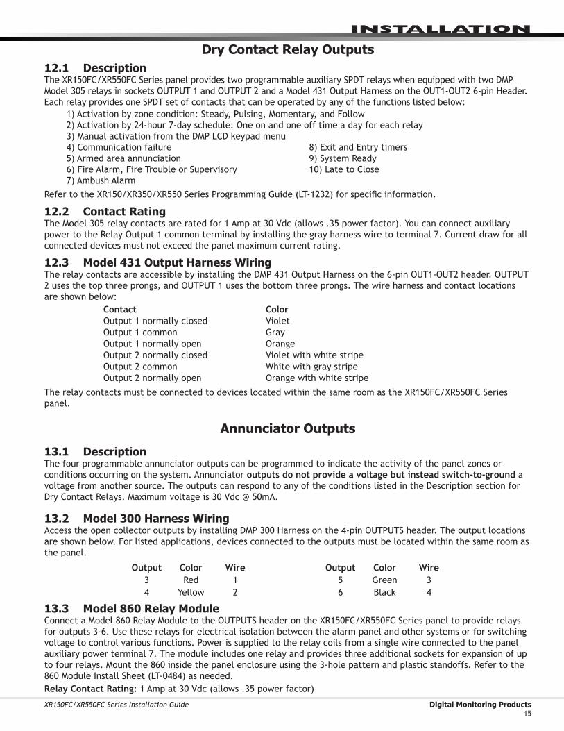
Dry Contact Relay Outputs12.1 DescriptionThe XR150FC/XR550FC Series panel provides two programmable auxiliary SPDT relays when equipped with two DMP Model 305 relays in sockets OUTPUT 1 and OUTPUT 2 and a Model 431 Output Harness on the OUT1-OUT2 6-pin Header. Each relay provides one SPDT set of contacts that can be operated by any of the functions listed below:
1) Activation by zone condition: Steady, Pulsing, Momentary, and Follow2) Activation by 24-hour 7-day schedule: One on and one off time a day for each relay3) Manual activation from the DMP LCD keypad menu4) Communication failure 8) Exit and Entry timers5) Armed area annunciation 9) System Ready6) Fire Alarm, Fire Trouble or Supervisory 10) Late to Close7) Ambush Alarm
Refer to the XR150/XR350/XR550 Series Programming Guide (LT-1232) for specific information.
12.2 Contact RatingThe Model 305 relay contacts are rated for 1 Amp at 30 Vdc (allows .35 power factor). You can connect auxiliary power to the Relay Output 1 common terminal by installing the gray harness wire to terminal 7. Current draw for all connected devices must not exceed the panel maximum current rating.
12.3 Model 431 Output Harness WiringThe relay contacts are accessible by installing the DMP 431 Output Harness on the 6-pin OUT1-OUT2 header. OUTPUT 2 uses the top three prongs, and OUTPUT 1 uses the bottom three prongs. The wire harness and contact locations are shown below:
Contact ColorOutput 1 normally closed VioletOutput 1 common GrayOutput 1 normally open OrangeOutput 2 normally closed Violet with white stripeOutput 2 common White with gray stripeOutput 2 normally open Orange with white stripe
The relay contacts must be connected to devices located within the same room as the XR150FC/XR550FC Series panel.
Annunciator Outputs
13.1 DescriptionThe four programmable annunciator outputs can be programmed to indicate the activity of the panel zones or conditions occurring on the system. Annunciator outputs do not provide a voltage but instead switch-to-ground a voltage from another source. The outputs can respond to any of the conditions listed in the Description section for Dry Contact Relays. Maximum voltage is 30 Vdc @ 50mA.
13.2 Model 300 Harness WiringAccess the open collector outputs by installing DMP 300 Harness on the 4-pin OUTPUTS header. The output locations are shown below. For listed applications, devices connected to the outputs must be located within the same room as the panel.
Output Color Wire Output Color Wire3 Red 1 5 Green 34 Yellow 2 6 Black 4
13.3 Model 860 Relay ModuleConnect a Model 860 Relay Module to the OUTPUTS header on the XR150FC/XR550FC Series panel to provide relays for outputs 3-6. Use these relays for electrical isolation between the alarm panel and other systems or for switching voltage to control various functions. Power is supplied to the relay coils from a single wire connected to the panel auxiliary power terminal 7. The module includes one relay and provides three additional sockets for expansion of up to four relays. Mount the 860 inside the panel enclosure using the 3-hole pattern and plastic standoffs. Refer to the 860 Module Install Sheet (LT-0484) as needed.Relay Contact Rating: 1 Amp at 30 Vdc (allows .35 power factor)

Digital Monitoring Products XR150FC/XR550FC Series Installation Guide16
InstallatIon
Wireless Bus Expansion14.1 DescriptionThe Wireless Bus (XBUS) header provides connection for the 1100X or 1100XH Wireless Receiver. The XBUS provides up to 500 wireless zones numbered 500-999. Refer to the 1100X Wireless Receiver Install Guide (LT-0708) or the 1100XH Wireless Receiver Install Guide (LT-0970) for complete information.
• XR550 provides up to 500 zones• XR150 provides up to 100 zones
14.2 Wireless Bus LEDsThe two LEDs, located above the XBUS header, indicate data transmission and receipt. The left LED flashes green to indicate the panel is transmitting data. The right LED flashes yellow to indicate the panel is receiving data.
LX-Bus Expansion15.1 LX-Bus HeadersThere are five LX-Bus headers near the bottom of the panel:
• LX500, provides zones 500-599 (XR150FC/XR550FC)• LX600, provides zones 600-699 (XR550FC only)• LX700, provides zones 700-799 (XR550FC only)• LX800, provides zones 800-899 (XR550FC only)• LX900, provides zones 900-999 (XR550FC only)
15.2 LX-Bus LEDsThe two LEDs, located above each LX-Bus header, indicate data transmission and receipt. The left LED flashes green to indicate the panel is transmitting LX-Bus data. The right LED flashes yellow to indicate the panel is receiving LX-Bus data.
15.3 OVC LEDsThe Overcurrent LEDs (OVC) light Red when the devices connected to the Keypad Bus and LX-Bus(es) draw more current than the panel is rated for. The first OVC is located to the left of the 893A connector and the second is to the right of the CELL MODULE. Each LED turns a steady Red when lit. When the OVC LED lights Red, the LX-Bus(es) and Keypad bus are shut down.
ETHERNET Connector16.1 DescriptionThe ETHERNET connector is available on the XR150DNFC/XR550DNFC with Network to connect directly to an Ethernet network using a standard patch cable. The ETHERNET connector supports 100MB/s full duplex operation and the maximum impedance is 100 Ohms.
16.2 Ethernet LEDsThe two LEDs, located on the top edge of the connector, indicate network connection. The right, Link LED lights up green to indicate a valid receive connection from the host network. The yellow LED lights when connected to a 100Mb network and is off when connected to a 10Mb network.
16.3 Network Transient SuppressionFor listed fire applications, use a Model 270 Network Transient Suppression Module to provide transient surge protection for the ETHERNET connector.
Figure 7: LX-Bus Headers and LEDs
Figure 8: ETHERNET Header and LEDs
J1ETHERNET
Link LEDActivity LED

XR150FC/XR550FC Series Installation Guide Digital Monitoring Products17
InstallatIon
PHONE LINE RJ Connector17.1 DescriptionConnect the panel to the public telephone network by installing a DMP 356 RJ Cable between the panel PHONE LINE connector and the RJ31X or RJ38X phone block. The maximum impedance is 100 Ohms.
CAUTION - To reduce the risk of fire, use only No. 26 AWG or larger telecommunication line cord, such as DMP Model 356 Series Phone Cords.
17.2 893A OR 277 ConnectorConnect an 893A Dual Phone Line Module or a 277 Trouble Sounder to the 893A OR 277 connector on the XR150FC/XR550FC Series. Refer to the 893A Installation Sheet (LT-0135) or the 277 Installation Sheet (LT-1304) for complete information.
17.3 NotificationThe user must not repair registered terminal equipment. In case of trouble, immediately unplug the device from the telephone jack. The factory warranty provides for repairs. Registered terminal equipment may not be used on party lines or in connection with coin telephones. No tify the telephone company with the following information:
a. The particular line(s) where the service is connectedb. The FCC registration number as listedc. The ringer equivalenced. The device make, model, and serial number
17.4 Phone Line MonitorThe XR150FC/XR550FC Series panel has a built-in telephone monitor that monitors the phone line voltage to verify the connection to the central office. Figure 8 and the table below identify the phone block pin layout, wire numbers, and colors. Wire Number Wire Color
1 Gray2 Orange3 Black4 Red5 Green6 Yellow7 Blue8 Brown
The wires on the RJ31 that feed pins 4 and 5 should be the ONLY wires on the D-marc. All other house phone wiring should be tied to pins 1 and 8 coming back from the RJ31.Dial tone must come into RJ31X on pins 4 and 5 and go back to house phones from pins 1 and 8. Follow these steps to determine if panel is seizing the line:
1. Unplug phone cord from RJ31X2. Place butt-set on pins 4 and 53. Listen for dial tone. With dial tone present, lift either wire from pins 1 or 84. Listen for dial tone again. If the dial tone is present, RJ31X wiring is correct. If no dial tone is present, the
RJ31X wiring is backwards. Rewire so dial tone is coming IN on 4 and 5.If you still have trouble with the phone line, you may need to replace the RJ cord. If the dial tone is still not present, swap out the RJ31X phone block.17.5 FCC RegistrationThe Model XR150FC/XR550FC Series complies with Part 68 of the FCC rules and the requirements adopted by the ACTA. On the outside of the enclosure of this equipment is a label that contains, among other information, a product identifier in the format US:CCKAL00BXR550. If requested this number must be provided to the telephone company.A plug and jack used to connect this equipment to the premises wiring and telephone network must comply with the applicable FCC Part 68 rules and requirements adopted by the ACTA. See installation instructions for details.The Ringer Equivalence Number (REN) is used to determine the number of devices that may be connected to a telephone line. Excessive RENs on a telephone line may result in the devices not ringing in response to an incoming call. In most but not all areas, the sum of RENs should not exceed five (5.0). To be certain of the number of devices that may be connected to a line, as determined by the total RENs, contact the local telephone company.If the XR150FC/XR550FC Series causes harm to the telephone network, the telephone company will notify you in advance that temporary discontinuance of service may be required. But if advance notice isn’t practical, the
To Telephone Line
RJ31X or RJ38X Phone Block
8
7
6
5 4
3
2
1
Ring Tip
To Premise Phone
Ring 1Tip 1
Figure 9: Phone Jack Wiring

Digital Monitoring Products XR150FC/XR550FC Series Installation Guide18
InstallatIon
telephone company will notify the customer as soon as possible. Also, you will be advised of your right to file a complaint with the FCC if you believe it is necessary.The telephone company may make changes in its facilities, equipment, operations or procedures that could affect the operation of the equipment. If this happens the telephone company will provide advance notice in order for you to make necessary modifications to maintain uninterrupted service.If trouble is experienced with the Model XR150FC/XR550FC Series, for repair or warranty information, please contact DMP at the address and telephone number listed on the back of this document. If the equipment is causing harm to the telephone network, the telephone company may request that you disconnect the equipment until the problem is resolved.If your premises has specially wired alarm equipment connected to the telephone line, ensure the installation of the XR150FC/XR550FC Series does not disable your alarm equipment. If you have questions about what will disable alarm equipment, consult your telephone company or a qualified installer.Caution: To ensure proper operation, this equipment must be installed according to the installation instructions in this manual. To verify that the equipment is operating properly and can successfully report an alarm, this equipment must be tested immediately after installation, and periodically thereafter, according to the test instructions in this document and the XR150/XR350/XR550 Series Programming Guide (LT-1232). Additionally, verification of Line Seize capability should be made immediately after installation, and periodically thereafter, in order to ensure that this equipment can initiate a call even when other equipment (telephone, answering system, computer modem, etc.) connected to the same line is in use.
RESET and TAMPER Headers18.1 RESET Header The RESET header is located to the left of the EXP Expansion Header on the right side of the circuit board and is used to reset the XR150FC/XR550FC Series microprocessor. To reset the panel when first installing the system, install the reset jumper before applying power to the panel. After connecting the AC and battery, remove the reset jumper.
To reset the panel while the system is operational, for example, prior to reprogramming, install the reset jumper without powering down the system. Remove the reset jumper after one or two seconds.
After resetting the panel, begin programming within 30 minutes. If you wait longer than 30 minutes, you must reset the panel again.
18.2 TAMPER HeaderThe TAMPER header is for use with the optional DMP 306 Tamper Harness. The harness connects to one or more tamper switches mounted inside the panel enclosure to supervise against unauthorized enclosure opening or removal. Refer to the wiring diagram on the enclosure door for correct tamper switch wiring.
How the Tamper WorksIf the enclosure is opened or removed while one or more of the system areas are armed, a panel tamper alarm is indicated. If all areas are disarmed, a panel tamper trouble is indicated.
Figure 10: XR550FC Series Panel Showing the RESET
Jumper
Momentarily place the Reset jumper over both of the J16 pins to reset the panel.
K

XR150FC/XR550FC Series Installation Guide Digital Monitoring Products19
LT-1
297
© 2
015
Dig
ital
Mon
itor
ing
Prod
ucts
, In
c.
800-641-4282
www.dmp.com
Designed, Engineered and Assembled in the USA
INTRUSION • FIRE • ACCESS • NETWORKS
2500 North Partnership Boulevard
Springfield, Missouri 65803-8877
1543
5
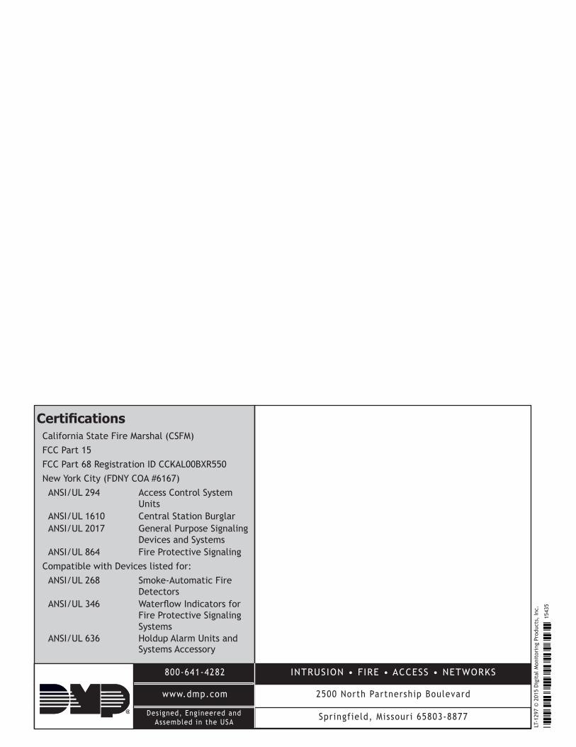
CertificationsCalifornia State Fire Marshal (CSFM)FCC Part 15FCC Part 68 Registration ID CCKAL00BXR550New York City (FDNY COA #6167)ANSI/UL 294 Access Control System
UnitsANSI/UL 1610 Central Station BurglarANSI/UL 2017 General Purpose Signaling
Devices and SystemsANSI/UL 864 Fire Protective Signaling
Compatible with Devices listed for:ANSI/UL 268 Smoke-Automatic Fire
DetectorsANSI/UL 346 Waterflow Indicators for
Fire Protective Signaling Systems
ANSI/UL 636 Holdup Alarm Units and Systems Accessory