INSTALLATION GUIDE - Big Ass Solutions · INSTALLATION GUIDE AirGo® Misting System For help, call...
20
INSTALLATION GUIDE AirGo ® Misting System For help, call 1-877-BIG-FANS or visit www.bigassfans.com
Transcript of INSTALLATION GUIDE - Big Ass Solutions · INSTALLATION GUIDE AirGo® Misting System For help, call...
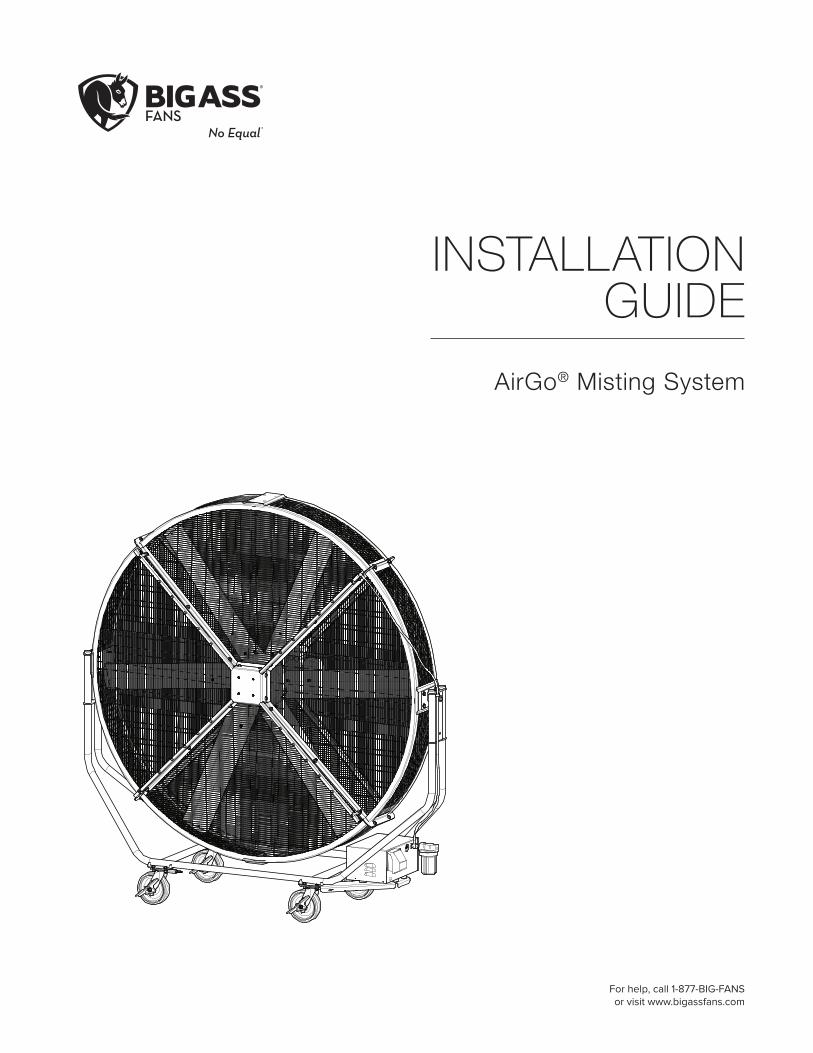
INSTALLATION GUIDE
AirGo® Misting System
For help, call 1-877-BIG-FANS or visit www.bigassfans.com

Big Ass Fans2348 Innovation DriveLexington, KY 405111-877-BIG-FANSwww.bigassfans.com
READ AND SAVE THESE INSTRUCTIONS
WARNING AND CAUTION SYMBOLIndicates a hazard with a medium level of risk that could result in injury or death or damage to property if not avoided.
ELECTRICAL WARNING SYMBOL Indicates an electrical hazard with a medium level of risk that could result in death or serious injury if not avoided.
This product was manufactured in a plant whose Management System is certified as being in conformity with ISO 9001.
LegalImproper installation, delivery, or maintenance, including, but not limited to, any of the following actions by the customer or agent of the customer will constitute a breach of and will void all warranties:
• Failure to follow the required installation procedures specified in this Installation Guide and in all other documentation supplied with the fans and related equipment including documentation provided by the manufacturers of the individual fan and control components;
• Failure to follow all relevant codes and ordinances, including, but not limited to, the National Electric Code (United States), applicable national and local electrical codes, and state and local building codes;
• Failure to follow electrical engineering industry standards regarding the approved method of installing solid-state electrical equipment having the characteristics of the fans, the fan controls, and their related components, even if such standards are not specifically referenced in any instructions or literature supplied by Big Ass Solutions or provided by manufacturers.
AirGo is a trademark of Delta T Corporation. All other trademarks used herein are the properties of their respective owners. No part of this document may be reproduced or translated into a different language without the prior written consent of Big Ass Solutions. The information contained in this document is subject to change without notice. For the most up-to-date information, see the online installation guide at www.bigassfans.com.
www.bigasssolutions.com/patents ▪ www.bigasssolutions.com/warranties
Installation GuideJuly 2017Rev. G
Original English Instructions

CONTENTSIntroduction Safety Instructions ii
Parts and Hardware 1
Installing the Misting System
1. Attach Casters and Misting Pump Bracket (AirGo®) 22. Remove Oil Plug 33. Install Filter 34a. Install Misting Pump (AirGo) 44b. Install Misting Pump (AirGo All-Terrain) 55. Connect High Pressure Hose to Pump 66. Connect Water Supply 6
Operating the Misting System
Starting and Stopping 7Misting Pump Diagram 7
Maintenance Service Schedule 8Draining and Storing 8Cleaning the Misting Nozzles 9Troubleshooting 9Internal Pump Parts Diagram and Parts List 10
Service Procedures Changing the Oil 11Servicing the Regulator 11Servicing the Plunger 12Servicing the Crankcase 13Servicing the Inlet/Discharge Valve 13Servicing the Seal Kit 14

IMPORTANT SAFETY INSTRUCTIONS
TO REDUCE THE RISK OF FIRE, ELECTRIC SHOCK, OR INJURY TO PERSONS, OBSERVE THE FOLLOWING:
WARNING: The fan must be installed with hardware that is marked to indicate suitability with this model. Other hardware cannot be substituted.
CAUTION: Installation work and electrical wiring must be done by qualified person(s) in accordance with all applicable codes and standards.
CAUTION: Use this fan only in the manner intended by the manufacturer. If you have questions, contact the manufacturer.
CAUTION: The installation of a Big Ass Fan must be in accordance with the requirements specified in this installation manual and with any additional requirements set forth by the National Electric Code (NEC), ANSI/NFPA 70-2011, and all local codes. Code compliance is ultimately YOUR responsibility! Failure to comply with these codes could result in personal injury or property damage.
CAUTION: Exercise caution and common sense when powering the fan. Do not connect the fan to a damaged or hazardous power source. Do not attempt to resolve electrical malfunctions or failures on your own. Contact Big Ass Fans if you have any questions regarding the use of this fan.
CAUTION: When service or replacement of a component in the fan requires the removal or disconnection of a safety device, the safety device is to be reinstalled or remounted as previously installed.
WARNING: Before servicing or cleaning unit, switch power off at service panel and lock the service disconnecting means to prevent power from being switched on accidentally. When the service disconnecting means cannot be locked, securely fasten a prominent warning device, such as a tag, to the service panel.
WARNING: Risk of fire, electric shock, or injury to persons during cleaning and user-maintenance! Disconnect the fan from the power supply before servicing.
CAUTION: Do not bend the airfoils when installing, adjusting, or cleaning the fan. Do not insert foreign objects between rotating fan airfoils.
WARNING: Stay alert, watch what you are doing, and use common sense when installing fans. Do not install fans if tired or under the influence of drugs, alcohol, or medication. A moment of inattention while installing fans may result in serious personal injury.
CAUTION: Do not operate fan with a damaged cord or plug. Return fan to an authorized service facility for examination or repair.
CAUTION: Do not run cord under carpeting. Do not cover cord with throw rugs, runners, or similar coverings. Do not route cord under furniture or appliances. Arrange cord away from traffic area where it will not be tripped over.
CAUTION: The Big Ass Fans product warranty will not cover equipment damage or failure caused by improper installation.
CAUTION: The fan and misting system require a dedicated 15 A circuit to operate; however, Big Ass Fans recommends operating on a dedicated 20 A circuit. If operating the fan and misting system on a 15 A circuit, you may need to reduce the fan speed.
WARNING: Remove the oil plug on the motor before operating the misting pump!
WARNING: Do not operate the misting pump without the filter!
CAUTION: Do not plug the fan into an outlet on the misting pump!

WWW.BIGASSSOLUTIONS.COM © 2016 DELTA T CORP. ALL RIGHTS RESERVED. 1
(4) 5/16-18 Nylock Nut2
Misting Pump Bracket1 Misting Pump(4) Misting
Nozzle3 Filter4
PARTS AND HARDWAREThe following instructions are for installing, operating, and servicing the AirGo® Misting System. Consult the complete AirGo Installation Guide and the AirGo All-Terrain installation instructions for all other aspects of fan installation, operation, and safety information.
The parts and hardware listed below are only for the misting system. For a complete list of fan parts and hardware, see the AirGo Installation Guide or the AirGo All-Terrain installation instructions. If you are missing any parts or hardware required for installation, contact Customer Service.
Note: The illustrations below are not to scale.
1. The misting pump bracket will not be used if you are installing the misting system on an AirGo All-Terrain fan.
2. During shipping, the nuts secure the misting pump to a board. The board is attached to the shipping crate. During installation, you will remove the board from the crate, remove the nuts and misting pump from the board, and use the nuts to attach the misting pump to the fan.
3. Twenty (20) misting nozzles are pre-installed on the fan. The four (4) additional provided nozzles are spare parts.
4. The filter must be installed on the misting pump enclosure. Do not operate the misting pump without the filter!
Note: The following parts are pre-installed on the fan: (4) misting rails and hardware, (20) misting nozzles (5 installed in each misting rail), a high pressure hose, and a cover plate in the center of the fan. These parts are not included on the regular AirGo fan.

WWW.BIGASSSOLUTIONS.COM © 2016 DELTA T CORP. ALL RIGHTS RESERVED.2
INSTALLING THE MISTING SYSTEMCAUTION: At least two (2) installation personnel are required during installation!
If you are installing the misting system on an AirGo All-Terrain fan, complete all steps in the AirGo All-Terrain installation instructions before proceeding.
The misting pump must be installed on the same side of the fan as the high pressure hose. If you are facing the front of the fan (the side with the misting rails), install the pump on the right side of the fan support frame.
1. Attach casters and misting pump bracket (AirGo)
Remove the fan from the shipping crate and elevate the cage. Consult the complete AirGo Installation Guide for details.
Place the misting pump bracket under the two (2) caster pads on the right side of the fan support frame. Make sure you are facing the front of the fan. Align the eight (8) holes in the back of the bracket with the eight holes on the pads. Attach the bracket and casters with the Caster Hardware.
Caster Hardware:a. (16) 3/8” Hex Bolt b. (32) 3/8” Flat Washerc. (16) 3/8” Nylock Nut
a
b
c
b
ab
b
c
If you are installing the misting system on an AirGo All-Terrain fan, skip this step and proceed to step 2.
Ensure the swivel lock rings on the casters are pointing inward.

WWW.BIGASSSOLUTIONS.COM © 2016 DELTA T CORP. ALL RIGHTS RESERVED. 3
2. Remove oil plugDuring shipping, the misting pump is secured to a board. The board is attached to the shipping crate. Remove the board from the shipping crate and discard the screws. Remove the misting pump from the board by unscrewing the four (4) nuts securing the pump feet to the board. Set the nuts aside. You will use them to attach the misting pump to the fan.
Remove all screws from the sides of the misting pump enclosure. Lift the enclosure to reveal the motor. Remove the oil plug (item #24 in the diagram on p. 10) from the motor, and then reinstall the enclosure on the misting pump.
3. Install filterInstall the filter on the pump enclosure by screwing it into the inlet.
Note: If you are installing the misting pump on an AirGo All-Terrain fan, attach the filter so that it is tilted slightly instead of hanging vertically. This helps the filter fit next to parts of the fan frame more easily when the misting pump is installed.
Filter
Inlet
Outlet
Remove only item #24 as shown in the diagram on p. 10.
WWW.BIGASSSOLUTIONS.COM © 2016 DELTA T CORP. ALL RIGHTS RESERVED.4
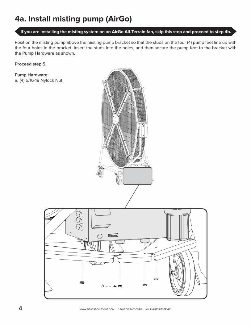
4a. Install misting pump (AirGo)
Position the misting pump above the misting pump bracket so that the studs on the four (4) pump feet line up with the four holes in the bracket. Insert the studs into the holes, and then secure the pump feet to the bracket with the Pump Hardware as shown.
Proceed step 5.
Pump Hardware:a. (4) 5/16-18 Nylock Nut
a
If you are installing the misting system on an AirGo All-Terrain fan, skip this step and proceed to step 4b.
WWW.BIGASSSOLUTIONS.COM © 2016 DELTA T CORP. ALL RIGHTS RESERVED. 5
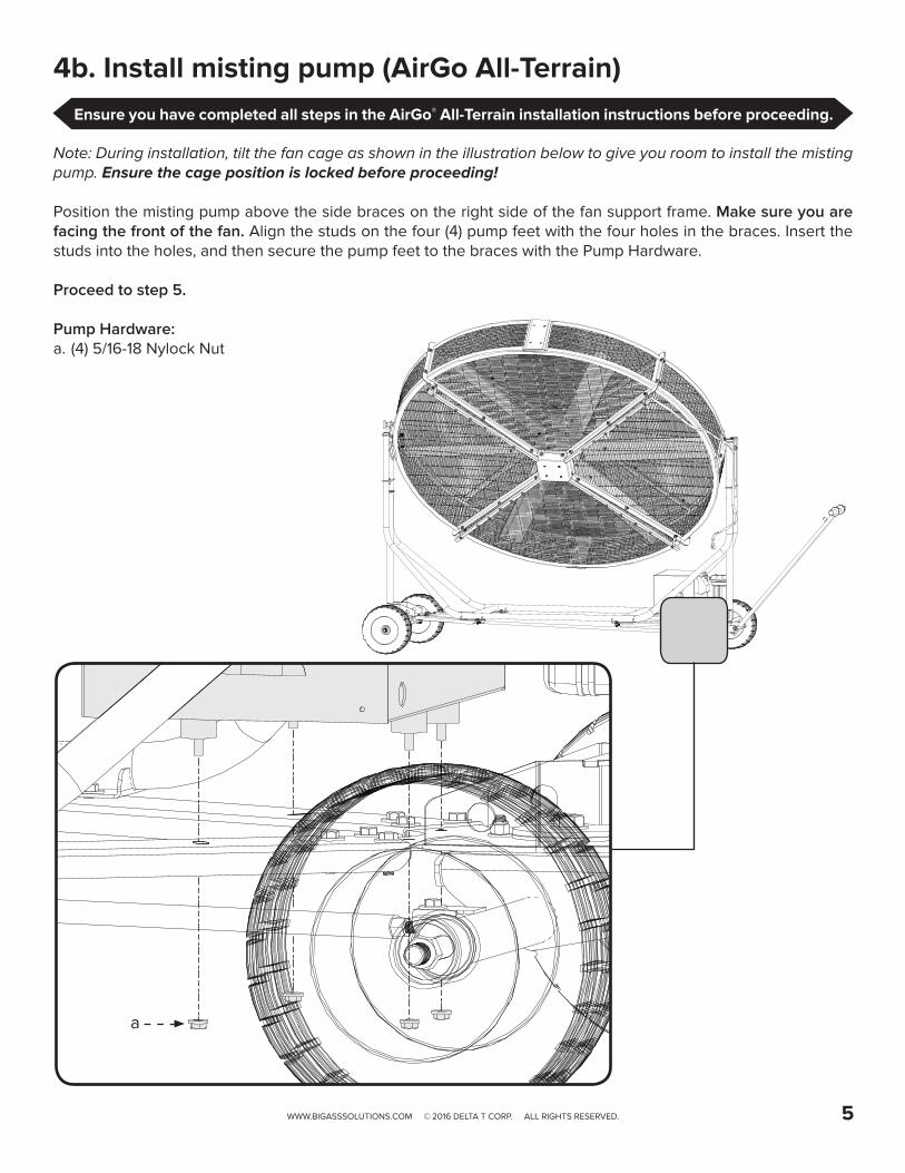
4b. Install misting pump (AirGo All-Terrain)
Note: During installation, tilt the fan cage as shown in the illustration below to give you room to install the misting pump. Ensure the cage position is locked before proceeding!
Position the misting pump above the side braces on the right side of the fan support frame. Make sure you are facing the front of the fan. Align the studs on the four (4) pump feet with the four holes in the braces. Insert the studs into the holes, and then secure the pump feet to the braces with the Pump Hardware.
Proceed to step 5.
Pump Hardware:a. (4) 5/16-18 Nylock Nut
a
Ensure you have completed all steps in the AirGo® All-Terrain installation instructions before proceeding.
WWW.BIGASSSOLUTIONS.COM © 2016 DELTA T CORP. ALL RIGHTS RESERVED.6
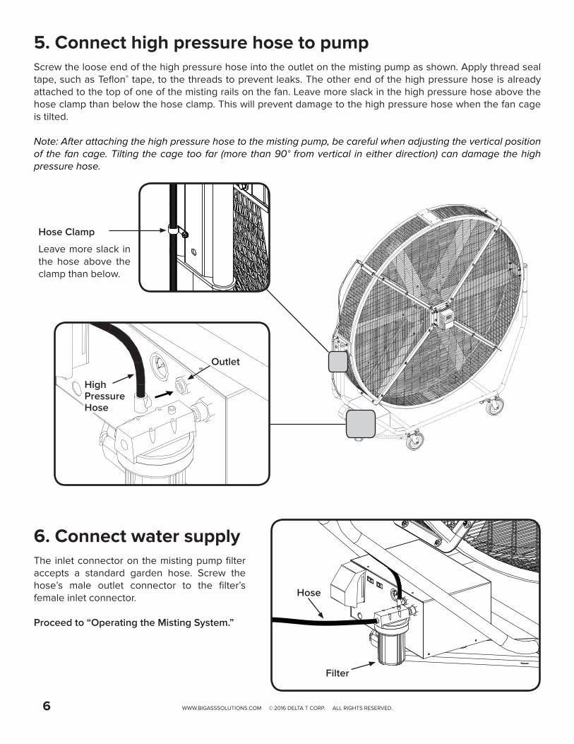
6. Connect water supplyThe inlet connector on the misting pump filter accepts a standard garden hose. Screw the hose’s male outlet connector to the filter’s female inlet connector.
Proceed to “Operating the Misting System.”
Hose
Filter
5. Connect high pressure hose to pumpScrew the loose end of the high pressure hose into the outlet on the misting pump as shown. Apply thread seal tape, such as Teflon® tape, to the threads to prevent leaks. The other end of the high pressure hose is already attached to the top of one of the misting rails on the fan. Leave more slack in the high pressure hose above the hose clamp than below the hose clamp. This will prevent damage to the high pressure hose when the fan cage is tilted.
Note: After attaching the high pressure hose to the misting pump, be careful when adjusting the vertical position of the fan cage. Tilting the cage too far (more than 90° from vertical in either direction) can damage the high pressure hose.
Outlet
HighPressureHose
Hose Clamp
Leave more slack in the hose above the clamp than below.

WWW.BIGASSSOLUTIONS.COM © 2016 DELTA T CORP. ALL RIGHTS RESERVED. 7
OPERATING THE MISTING SYSTEMCAUTION: The fan and misting system require a dedicated 15 A circuit to operate; however, Big Ass Fans recommends operating on a dedicated 20 A circuit. If operating the fan and misting system on a 15 A circuit, you may need to reduce the fan speed.
WARNING: Remove the oil plug on the motor before operating the misting pump!
WARNING: Do not operate the misting pump without the filter!
CAUTION: Do not plug the fan into an outlet on the misting pump!
Starting and stopping
Refer to the diagram below for identification of the parts of the misting pump.
To operate the AirGo Misting System:1. Make sure the fan is stopped.2. Plug the misting pump into an outlet (15 A or 20 A circuit). The AirGo fan and misting system require a dedicated
15 A circuit to operate; however, Big Ass Fans recommends operating the fan and misting system on a dedicated 20 A circuit. If you are operating the fan and misting system on a 15 A circuit, you may need to reduce the fan speed.
3. Turn on the water source.4. Press the red button on the misting pump filter to purge the air out of the filter.5. Flip the Power switch on the misting pump to the ON position.6. Press the Start switch on the misting pump. The fan should begin misting.7. Turn on the fan.
To stop the misting system and resume normal fan operation, flip the Power switch on the misting pump to the OFF position, and then turn off the water source. If you want to start using the misting system again, make sure you stop the fan before restarting the misting pump. Note: If you restart the misting pump within three minutes of turning it off, the fan will begin misting automatically when you flip the Power switch to the ON position. You do not need to press the Start switch.
Note: The misting system is most effective when the fan is run at higher speeds in hot, dry weather, allowing the mist to evaporate quickly before settling.
Power Outlets
Power Switch
Start Switch
Pressure Gauge
Inlet (filter not shown)
Outlet
GFCI Power Cord
The inlet water supply pressure must be between 15 and 60 PSI (60 PSI maximum). The inlet water supply temperature must be below 140ºF (60ºC). Damage to the misting pump can occur if the supply pressure is higher than 60 PSI or if the supply temperature is higher than 140º F (60º C). If your water supply pressure is higher than 60 PSI, you will need to install a pressure regulator.

WWW.BIGASSSOLUTIONS.COM © 2016 DELTA T CORP. ALL RIGHTS RESERVED.8
MAINTENANCEWARNING: Disconnect the fan and misting pump from power before servicing!
Service scheduleTo ensure proper performance of the AirGo Misting System, we suggest performing the following procedures according to the schedules listed. The temperature and quality of the supply water affect the wear on pump parts. Note: Also perform the fan preventive maintenance procedures listed in the complete AirGo Installation Guide.
Schedule Procedure50 hours of operation Initial oil change
300 hours of operationChange the oil.If ISO 68 Crankcase Oil Special Formula Premium Grade is used, change the oil after every 500 hours of use. Contact Customer Service to purchase.
1,500 hours of operation
Change the seals.If system performance decreases, check immediately. If no wear is observed, check again after 2,000 hours of operation.
3,000 hours of operation
Change the relief valve. Service the relief valve at every other seal change and check connections before resuming.
MonthlyCheck the oil level.Check for oil leaks.Check for water leaks.
Annually
Clean the misting nozzles.To prevent clogs caused by mineral deposits, clean the misting nozzles annually using a commercial mineral deposit cleaner such as Orbit® Misting Nozzle Cleaner or Lime-A-Way®. Depending on the mineral content of the water, the nozzles may need to be cleaned more frequently. Check the nozzles regularly for clogs. Observe each nozzle to ensure it is producing an even cone of mist. If any nozzles are spraying irregularly, clean the nozzles. See the following page for cleaning instructions.
Seasonally
Winterize the misting pump seasonally if it will be stored in temperatures at or below 32° F/0° C.To winterize the misting pump:1. Flush the pump with fresh water.2. Press the relief valve to relieve line pressure. Disconnect the water supply hose from the filter
and disconnect the high pressure hose from the top of the fan.3. Flush the system by connecting a short hose to the pump inlet. Place the other end of the
hose in a container with half water and half antifreeze. 4. Operate the pump until antifreeze runs through the high pressure hose. 5. Disconnect power from the pump. Cover and store the pump in an appropriate location.
To restart the pump, reconnect the water supply hose and power supply. Turn on the pump for 2–3 minutes and check for leaks.
Draining and storingIf the fan and misting system will be unused or stored for more than one week, Big Ass Fans recommends draining the water out of the system. Note: To reconnect the high pressure hose to the misting pump, apply thread seal tape, such as Teflon® tape, to the threads on the end of the hose, and then screw the hose back into the pump outlet.
To drain the misting system:1. Tilt the fan cage forward 90° so that the cage is horizontal to the ground and the front of the cage is facing the ground.2. Disconnect the high pressure hose from the misting pump outlet.3. Unscrew the filter from the misting pump inlet.4. Allow the system to drain completely before storing.
If the misting system has been turned off for more than 24 hours, clear out the system by running it for one (1) minute before use to ensure clean water is flowing through the system before persons come into contact with the mist.

WWW.BIGASSSOLUTIONS.COM © 2016 DELTA T CORP. ALL RIGHTS RESERVED. 9
TroubleshootingWARNING: Disconnect the fan and misting Pump from power before servicing!
For questions about your product or customer service inquiries, please call our toll free number (877-BIG-FANS) or visit www.bigassfans.com/service. Some issues can be resolved before requesting service. Review the troubleshooting tips below before contacting Customer Service for support.
Cleaning the misting nozzlesBig Ass Fans recommends cleaning the misting nozzles annually to prevent clogs caused by mineral deposits.
To clean a misting nozzle:1. Unscrew and remove the nozzle from the misting rail.2. Disassemble the nozzle as shown below. Clean all parts of the nozzle using a commercial mineral deposit
cleaner. Big Ass Fans recommends Orbit® Misting Nozzle Cleaner or Lime-A-Way®. Be sure to clean the nozzle’s internal mesh screen. Refer to the illustration below.
3. Reassemble the nozzle as shown below.4. Apply a commercial thread sealant to the nozzle’s threads. The sealant should be approved for 1,000 PSI of
water and must work with plastic. Big Ass Fans recommends Loctite® 1537780 No More Leaks™ Plastic Pipe Thread Sealant or Oatey® 31230 Great White® Pipe Joint Compound with PTFE.
5. Screw the nozzle back into the misting rail and tighten to 60 in·lb (6.8 N·m).
Symptom Solution(s)
The misting pump stopped working or will not operate.
Water pressure or power may not be adequate.
• Verify power is applied and is adequate. Check your circuit breaker or fuse for functionality. Note: The fan and misting system require a dedicated 15 A circuit; however, Big Ass Fans recommends operating on a dedicated 20 A circuit.
• Press and hold the red button on the pump filter until water runs through the system. If water pressure is low or an air bubble occurs, the low pressure switch automatically trips.
• Ensure the pump’s Power switch is in the ON position and power is applied.• Check the filter. If it is dirty or clogged, replace it. Contact Customer Service to
purchase a replacement filter.
The misting nozzles are not working properly.
The nozzles may be clogged or water pressure is inadequate.
• Clean the misting nozzles using a commercial mineral deposit cleaner such as Orbit® Misting Nozzle Cleaner or Lime-A-Way®. Big Ass Fans recommends cleaning the nozzles annually to prevent clogs caused by mineral deposits. Depending on the mineral content of the water, the nozzles may need to be cleaned more frequently. See above for cleaning instructions.
• Check the misting pump’s pressure gauge to ensure water pressure is between 800 and 1,000 PSI. If it is less than 800, contact Customer Service.
The water has a bad odor.
If the misting system has not been used for a long period of time, water left in the system may produce a bad odor.
• Clear out the misting system by running fresh water through it for one (1) minute before resuming normal operation.
• If the misting system will not be used for a long period of time (more than one (1) week), drain the water out of the system after you are finished using it. See “Draining and Storing” for details.
Mesh Screen

WWW.BIGASSSOLUTIONS.COM © 2016 DELTA T CORP. ALL RIGHTS RESERVED.10
Internal pump parts diagram and parts list
174172
169167
166164
163168
167166
161160
188185
310
125121
120
99
300
106
9890
10070
65
64
32
24
33
53
5
3837
49
48
200
255
1011
8
15
20
25
27
400
408
410415
412
427
429
440
402
403
# Description Qty # Description Qty # Description Qty
5 Screw, Bearing Cover (M6 x 14) 3 65 Rod, Plunger 1 174 Plug, Valve with 1/4’” NPTF Port 1
8 Cover, Bearing 1 70 Seal, Oil (70D) 1 185 Head, Manifold 1
10 O-Ring, Bearing Cover (70D) 1 90 Plunger (M16 x 27) 1 188 Screw, HSH (M6 x 55) 4
11 Seal, Oil (70D) 1 98 Washer, Seal (90D) 1 200 Hose, Pulse (3/8” x 24”) 1
15 Bearing, Inner Ball 1 99 Retainer, Plunger (M6 x 35) 1 255 Assembly, Bolt Mount 1
20 Rod, Connecting 1 100 Retainer, Seal 1 300 Kit, Seal (Includes 98, 106, 121, & 125) 1
24 Plug, Oil Cap 1 106 Seal, LPS with S-Spg (85D) 1 310 Kit, Valve (Includes 160, 161, 163, 164, 166, 167, 168, 169, & 172) 1
25
Crankshaft (6.3 mm)
Crankshaft (2 mm)
Crankshaft (3.3 mm)
1
1
1
120 Case, Seal 1 400 Regulator 1
121 O-Ring, Seal Case (70D) 1 402 Cap, Hex Adjusting 1
125 Seal, HPS (85D) 1 403 Nut, Locking 1
27 Bearing, Outer Ball 1 160 O-Ring, Inlet Seat (70D) 1 408 Spring 1
32 Cap, Oil Filter with O-Ring 1 161 Seat, Inlet 1 410 Retainer, Spring 1
33 O-Ring, Oil Filler Cap (70D) 1 163 O-Ring, Discharge Seat (70D) 1 412 Stem, Piston 1
37 Sight Gauge (80D) 1 164 Seat, Discharge 1 415 O-Ring, Piston Stem (70D) 1
38 Gasket, Flat Flex, Oil Gauge (80D) 1 166 Valve 2 427 Seat 1
48 Plug, Drain 1 167 Spring 2 429 O-Ring, Seat (70D) 1
49 O-Ring, Drain Plug (70D) 1 168 Retainer, Inlet Spring 1 440 Body 1
53 Crankcase 1 169 Retainer, Discharge Spring 1 468 Kit, O-Ring (Includes 172, 415, & 429) 1
64 Pin, Crosshead 1 172 O-Ring, Discharge Fitting (70D) 1
DISCHARGE
BY-PASS
INLET
WWW.BIGASSSOLUTIONS.COM © 2016 DELTA T CORP. ALL RIGHTS RESERVED. 11
Changing the oilWARNING: Disconnect the fan and misting pump from power before changing the oil!
A drain pan and ISO 68 Crankcase Oil Special Formula Premium Grade are required when changing the oil. Refer to the diagram on the previous page for item number identification.
To change the oil on the misting pump:
1. Remove the drain plug (48) on the bottom of the pump. Allow the oil to drain into the drain pan, and then replace the drain plug (48).
2. Remove the oil cap (32) on top of the pump. 3. Pour ISO 68 Crankcase Oil Special Formula Premium Grade oil into the opening until the oil level reaches the
red dot on the sight gauge (37).4. Replace the oil cap (32).
Servicing the regulatorWARNING: Disconnect the fan and misting pump from power before servicing the regulator!
An O-Ring kit, M22 wrench, and an M6 allen wrench are required to service the regulator. Refer to the diagram on the previous page for item number identification.
To disassemble the regulator:5. Disconnect the discharge and bypass hoses from the pressure regulator (400).6. Loosen the hex valve plug (174) with an M22 wrench, and then remove the pressure regulator (400) from the
manifold head (185). Note: Do not separate the pressure regulator from the hex valve plug.
7. Remove the black adjusting cap (402) with an M6 allen wrench by turning it counterclockwise.8. Remove the exposed coil spring (408) and flat spring retainer (410).9. Carefully remove the piston stem (412) and o-ring (415).10. Remove the seat (427) and o-ring (429).
To inspect and reassemble the regulator:1. Examine the seat (427) and o-ring (429) for pitting or wear. Replace if damaged.2. Lubricate and install the o-ring (429) on the seat (427), and then press the seat into the regulator chamber with
the small diameter down until it is squarely seated.3. Examine the piston stem (412) and o-ring (415) for grooves, pitting, or wear. Replace if damaged.4. Lubricate and install the o-ring (415) on the piston stem (412), and then lower the piston stem into the regulator
chamber with the tapered end facing downward.5. Examine the flat spring retainer (410) and coil spring (408) for fatigue or breaks. Replace if damaged.6. Place the flat spring retainer (410) and spring (408) on top of the piston stem (412). 7. Hold the locking nut (403) on top of the spring (408), and then thread the black adjusting cap (402) into the
locking nut (403).8. Reconnect the bypass and discharge lines to the regulator (400).
SERVICE PROCEDURESWARNING: Disconnect the fan and misting pump from power before servicing!
Perform the following procedures according to the service schedule shown on p. 8.

WWW.BIGASSSOLUTIONS.COM © 2016 DELTA T CORP. ALL RIGHTS RESERVED.12
Servicing the plungerAn M10 hex tool and Loctite® Threadlocker Blue 242® are required to service the plunger. Refer to the parts diagram on p. 10 for item number identification.
To disassemble the plunger:1. Remove the four hex socket head screws (188) from the manifold head (185).2. Support the manifold head from the underside, and pull the manifold head away from the crankcase (53).3. Set aside the manifold head (185) with the crankcase side up.4. Remove the seal retainer (100) from the plunger rod (65). 5. Loosen the plunger retainer (99) on the plunger rod (65) approximately three to four turns with an M10 hex
tool.6. Push the ceramic plunger (90) toward the crankcase (53) to separate it from the plunger retainer (99). Unthread
the plunger retainer (99) by hand.7. Remove the ceramic plunger (90) and seal washer (98) from the plunger retainer (99).
To inspect and reassemble the plunger:1. Inspect the crankcase oil seal (70) for deterioration or leaks. If damaged, contact Big Ass Fans Customer
Service for a replacement, and refer to “Servicing the Crankcase.”2. Examine the seal washer (98) and the plunger retainer (99) for damage. Replace if damaged.3. Install the seal washer (98) on the plunger retainer (99).4. Examine the ceramic plunger (90) for scoring, scale buildup, chips, or cracks. Replace if damaged. Note: The
ceramic plunger does not need to be replaced with every seal servicing.
5. Slide the plunger retainer (99) with the seal washer (98) into the flat end of the ceramic plunger (90). 6. Apply Loctite® Threadlocker Blue 242® to the exposed, threaded end of the plunger retainer (99).7. Install the ceramic plunger (90) with the plunger retainer (99) and seal washer (98) on the plunger rod (65)
shoulder. Torque to 4.6 ft·lb (6.2 N·m). Note: The ceramic plunger can only be installed in one direction. The counterbore end of the ceramic plunger fits over the plunger rod shoulder.
8. Press the Lo-Pressure seal (106) into the seal case (120) with the garter spring down.9. Examine the ceramic plunger (90) for cracks or scale buildup. Replace if damaged.10. Slide the seal retainer (100) over the ceramic plunger (90) with the drain slots facing the crankcase (53) and
the openings upwards and downwards.11. Lightly lubricate the ceramic plunger (90). Carefully slide the manifold head (185) over the ceramic plunger,
supporting it from the underside to avoid damage. Press the manifold head until it is flush with the crankcase (53).
12. Thread the four hex socket head screws (188) into the manifold head. Torque the screws to 5.2 ft·lb (7 N·m) in the sequence shown below.
1 3
24
Torque Sequence

WWW.BIGASSSOLUTIONS.COM © 2016 DELTA T CORP. ALL RIGHTS RESERVED. 13
Servicing the crankcaseAn M10 hex tool and Loctite® 242® are required to service the crankcase. Refer to the parts diagram on p. 10 for item number identification.
To service the crankcase:1. Remove the manifold head (185), plunger (65), and retainer (99). See “Servicing the Plunger” for disassembly
instructions. 2. Examine the crankcase oil seal (70) for leaking or damage.3. Check for signs of leaking around the bearing cover (8), drain plug (48), and sight gauge (37).4. Check the oil level and for evidence of water in the oil. Ensure the oil is changed regularly. See the service
schedule on p. 8.5. Examine the crankshaft oil seal (11) for drying, cracking, or leaking. If damaged or leaking, contact Big Ass Fans
Customer Service.
Servicing the inlet/discharge valveAn M22 wrench and M8 screw are needed to service the valve. Refer to the parts diagram on p. 10 for item number identification. Note: The inlet valve seat, o-ring, and inlet spring retainer are different than the discharge valve seat, o-ring, and discharge spring retainer.
To disassemble the valve:6. Disconnect the discharge and bypass lines from the pressure regulator (400).7. Loosen the hex valve plug (174) with an M22 wrench, and then remove the regulator (400) from the manifold
head (185). Note: The pressure regulator does not need to be separated from the hex valve plug.
8. Remove the stacked valve assembly (310) from the valve chamber. 9. To separate the valve assemblies, thread an M8 screw into the bottom of the seat (161) until the screw contacts
the bottom of the valve (166).If the discharge valve assembly separates from the inlet valve assembly during removal, use pliers to remove the inlet valve assembly from the valve chamber.If the inlet spring retainer (168) separates from the inlet seat (161), remove the spring (167) and valve (166) from the valve chamber. Thread an M8 screw into the inlet seat (161) and remove it from the valve chamber.
10. Remove the o-rings (172, 163) from the seats (161, 164) and valve plug (174).
To inspect and reassemble the valve assembly:1. Reassembly can be done using a new, pre-assembled valve assembly (A) or using parts (B).
A. Press the pre-assembled valve assembly (310) into the valve chamber until fully seated. Skip to step 10.B. If reassembling using individual parts, proceed to step 2.
2. Examine the springs (167) for fatigue or breaks. Replace if damaged.3. Examine the valve (166) and seats (161, 164) for grooves, pitting, or wear. Replace if damaged.4. Examine the valve plug (174) and o-ring (172) for cuts or wear. Replace if damaged.5. Lubricate and install the o-ring (163) on the outside diameter of the discharge seat (164). Set aside the discharge
seat with the small diameter facing downward.6. Place the valve (166) on the discharge seat (164) with the concave side down, and then place the spring (167)
on the valve.7. Place the discharge spring retainer (169) over the spring (167) and snap it to the discharge seat (164).8. Assemble the inlet valve assembly in the order as above, and then snap the discharge valve assembly on the
inlet valve assembly. Press the entire assembly into the valve chamber until seated.

WWW.BIGASSSOLUTIONS.COM © 2016 DELTA T CORP. ALL RIGHTS RESERVED.14
Servicing the seal kitAn M5 allen wrench and a new seal kit are required to service the seal kit. Contact Big Ass Fans Customer Service for a replacement seal kit. Refer to the parts diagram on p. 10 for item number identification.
To disassemble the seal kit:
1. Remove the four hex socket head screws (188) from the manifold head (185).
2. Support the manifold head from the underside, and pull the manifold head away from the crankcase (53).
3. Set aside the manifold head (185) with the crankcase side up.
4. Remove the seal retainer (100) from the plunger rod (65).
5. Pry out the Lo-Pressure seal (106) from the seal case (120).
6. Remove the seal case (120) from the seal chamber with pliers.
7. Carefully roll the o-ring (121) off of the seal case (120).
8. Remove the Hi-Pressure seal (125).
To inspect and reassemble the seal kit:
1. Examine the manifold chamber walls (185) for scale buildup or damage.
2. Examine the Hi-Pressure seal (125) for frayed edges or uneven wear. Replace if damaged.
3. Examine the seal case o-ring (121) for cuts or deterioration. Replaced if damaged.
4. Examine the Lo-Pressure seal (106) for wear on the internal ridges and broken springs on the outer surfaces. Replace if damaged.
5. Examine the seal retainer (100) for deformities. Replace if damaged.
6. Lubricate and press the Hi-Pressure seal (125) into the seal chamber with the grooved side facing downward.
7. Lubricate and install the o-ring (121) on the seal case (120).
8. Press the Lo-Pressure seal (106) into the seal case (120) with the garter spring facing downward.
9. Examine the ceramic plunger (90) for cracks or scale buildup. If damaged, see “Servicing the Plunger.”
10. Slide the seal retainer (100) over the ceramic plunger (90) with the drain slots facing the crankcase (53) and the openings upwards and downwards.
11. Lightly lubricate the ceramic plunger (90). Carefully slide the manifold head (185) over the ceramic plunger, supporting it from the underside to avoid damage. Press the manifold head until it is flush with the crankcase (53).
12. Thread the four hex socket head screws (188) into the manifold head. Torque the screws to 5.2 ft·lb (7 N·m) in the sequence shown below.
1 3
24
Torque Sequence


2425 Merchant St., Lexington, KY 405111 (877) BIG-FANS | WWW.BIGASSFANS.COM
003525
Rev. G