Installation example for direct mounting
12
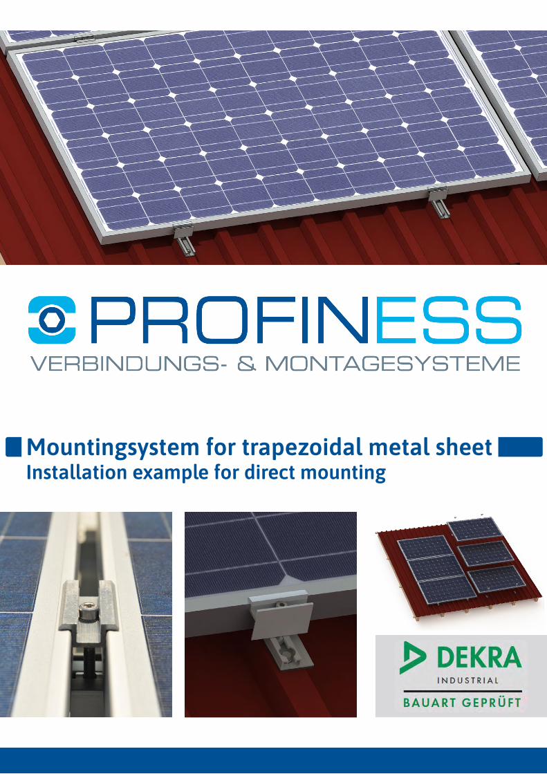
Mountingsystem for trapezoidal metal sheet Installation example for direct mounting
Transcript of Installation example for direct mounting
Mountingsystem for trapezoidal metal sheetInstallation example for direct mounting

www.profiness.de • Tel. +49 (0) 208 309 61 90 • PROFINESS GmbH • Broicher Waldweg 42 • 45478 Mülheim a.d. Ruhr 02
BASIC INFORMATION 03
ASSEMBLY OF CONTINUOUS PROFILES 04Roof constuction 04Components 04
MOUNTING 05Mounting sequence for continuous profile-laying 05Mounting sequence for profile-laying in pieces (each about 2 beads) 06New version for landscape mounted modules (and clamping on the long side of the frame) 07Predrilled high beading rail „Drehfix“ 09Trapezoidal sheet metal mounting with 5° additional inclination 10
CHECKLIST FOR TRAPEZOIDAL METAL SHEET ROOFS 11
CONTACT 12
Incl. new 5° elevation system Incl. Drehfix2020
NEW
CHAPTERS

www.profiness.de • Tel. +49 (0) 208 309 61 90 • PROFINESS GmbH • Broicher Waldweg 42 • 45478 Mülheim a.d. Ruhr 03
BASIC INFORMATION
We are delighted that you have chosen a PROFINESS system and thank you for your confidence in us.Please check, before construction starts, the completeness of the components based on our delivery note.Condition for any warranty claims is the observance of these installation instructions.
Observe the following instructions regarding laws, regulations and technical rules When setting up solar energy installations applicable laws and regulations at regional, national and European, and international level have to be observed for the respective country.It generally apply the general accepted rules of technology that have been usually formulated in the form of standards, guidelines, rules, regulations and technical rules by state and federal agencies, utility companies, and trade associations and committees in the relevant fields.The entire PV system must be installed in accordance with generally accepted engineering standards. Please observe the accident prevention regula-tions of the professional associations (trade association regulation for safety and health at work), in particular:BGV A1 General regulationsBGV A2 Electrical systems and equipmentBGV A3 Electrical systems and equipmentBGV C22 Construction workBGV D36 Ladders and steps
Please note all public regulations and standards, DIN standards, TAB (technical connection conditions), accident prevention regulations, the guidelines of the Association of Property Insurers (VDE guidelines for fire protection), the technical rules of the German Roofing Trade and General guidelines (eg timber structures, roof Overlap - and roof sealing work) in the planning, construction, operation and maintenance of grid-connected PV systems.These are in particular (not exhaustive):DIN / VDE 0100 part 712 in particular (construction of power plants with rated voltages up to 1000V)DIN / VDE 0289 (Electrical cables)VDI 6012 (Decentralized energy systems in buildings - Photovoltaics)DIN / VDE 0185 Part 1- 4 (lightning protection)DIN 1055 Part 4 (wind)EN 1991-1-4 (wind loads Euro Code 1)DIN 1055 Part 5 (snow load)EN 1991-1-3 (snow loads Euro Code 1)DIN 18338 Roofing and roof sealing worksDIN 18451 Scaffolding workDIN 1052 Part 2 and Part dimensioning of the substructure (wooden structures)TAB (technical connection conditions of the power company)DIN 18015 (design and construction of electrical installation in residential buildings)VDEW (guidelines concerning the connection and parallel operation of generators in the public low voltage network)DIN 4108 Thermal insulationEnergy Saving Regulation (EnEV)
ATTENTIONUnauthorized modifications and inappropriate use of our components in assembly and construction of the system for all liability claims.We would like to point out once again that when working on the roof, to observe accident prevention regulations (UVV) are (among others VBG 37 Construction work, § 12 Fall Protection).Furthermore, we point out that before the planning and construction of the installation of the building (structural, rafters, battens), or the roof clad-ding or foil on the roof serviceability and tightness must be checked.In foil roofs is to ensure that the compatibility of the roof sheet with the coating of the support surface used by Profiness tolerated.It is to ensure that distances to the roof end / attica on each plant site are respected. If this border area is too small, so this affects possibly negative effect on the static and must be considered accordingly.The modules, the dimensions are gem. Data observed in order to ensure the ventilation of the PV system. (See data sheet).
Work and knowledge requirement of processors and installersPROFINESS assumes that the assembly will be done only by competent personnel with a recognized qualification -or- (by a state or federal organiza-tion) appropriate knowledge - carried out the relevant technical area.

www.profiness.de • Tel. +49 (0) 208 309 61 90 • PROFINESS GmbH • Broicher Waldweg 42 • 45478 Mülheim a.d. Ruhr 04
Basic information regarding screwing with self-drilling screws on trapezoidal sheet metal:To prevent the screw from turning and especially to avoid damaging the sealing washer, we recommend a tightening torque of 3 - max. 5 Nm.(Under no circumstances higher!)
We recommend a not too high processing speed of approx. 1,200 rpm when screwing onto trapezoidal sheet metal.
ASSEMBLY OF CONTINUOUS PROFILES
ROOF CONSTUCTIONThe trapezoidal rails Profiness31 (1.3cm height) and Profiness31-60 (6cm height) are the connecting piece between the roof and the module. First, the EPDM sealing tape is adhered to the beads or to the rail, then the profile is placed. The connection to the roof is mady by self-drilling screw or rivet with building approval.
PROFINESS31 flat PROFINESS31 6cm high
Length 6.2 meters or cut to bridge for 2 beads
Self-drilling screws 6.3x25 with building authority approval. Also available as thin sheet metal screw 6.0x25
Length 6.2 meters or cut to bridge for 2 beads
Self-drilling screws 6.3x25 with building authority approval. Also available as thin sheet metal screw 6.0x25
COMPONENTS
It must be ensured that the adjacent components and fastening materials also have sufficient strength and can absorb and transfer the loads. We can statically calculate the number of fastening points free of charge; the statics of the roof substructure in connection with the local conditions must be checked on site.
correct too tight too low diagonal

www.profiness.de • Tel. +49 (0) 208 309 61 90 • PROFINESS GmbH • Broicher Waldweg 42 • 45478 Mülheim a.d. Ruhr 05
MOUNTING
MOUNTING SEQUENCE FOR CONTINUOUS PROFILE-LAYING
As a rule, the EPDM sealing tape is cut into pieces to match the bead width and glued onto the beads. The profiles are then The profiles are then scre-wed onto the beads according to the module layout and matching the clamping area of the modules. Always drill 2 holes (i.e. 4 in total) on the beads before and after a module clamp. (i.e. a total of 4 self-drilling screws per module clamp) or more, depending on the result of the static calculation.

www.profiness.de • Tel. +49 (0) 208 309 61 90 • PROFINESS GmbH • Broicher Waldweg 42 • 45478 Mülheim a.d. Ruhr 06
MOUNTING SEQUENCE FOR PROFILE-LAYING IN PIECES (EACH ABOUT 2 BEADS)
For each module clamp, one rail piece is screwed to the top beads with 4 self-drilling screws. The positioning depends on the module assignment and the clamping area of the modules. Depending on the result of the project statics, more than 2 module clamps per frame side may have to be mounted in edge areas.

www.profiness.de • Tel. +49 (0) 208 309 61 90 • PROFINESS GmbH • Broicher Waldweg 42 • 45478 Mülheim a.d. Ruhr 07
NEW VERSION FOR LANDSCAPE MOUNTED MODULES (AND CLAMPING ON THE LONG SIDE OF THE FRAME)
Thus modules landscape mounted not need to be clamped to the short side, we have developed a new profile, which is mounted only on the upper bead and towards this. Fixing is by two self-drilling screws, which are sufficient in most sheet constellations. If more drilling screws are required according to the project statics, additional short rails and clamps must be fitted on each side of the frame.
The fastening of the modules is analogous to that in the previous pages, only that the modules are landscape that clamping is also on the long module frame side.
We will be happy to provide you with structural analyses. Please complete the corresponding checklist, which you will find at the end of the document.

www.profiness.de • Tel. +49 (0) 208 309 61 90 • PROFINESS GmbH • Broicher Waldweg 42 • 45478 Mülheim a.d. Ruhr 08

www.profiness.de • Tel. +49 (0) 208 309 61 90 • PROFINESS GmbH • Broicher Waldweg 42 • 45478 Mülheim a.d. Ruhr 09
PREDRILLED HIGH BEADING RAIL „DREHFIX“
The assembly sequence is the same as the previous high beading rail. Each rail piece is screwed to the high bead with 2 self-drilling screws.The Drehfix rail is already pre-drilled. The module clamps are screwed in, not clicked in.

www.profiness.de • Tel. +49 (0) 208 309 61 90 • PROFINESS GmbH • Broicher Waldweg 42 • 45478 Mülheim a.d. Ruhr 10
TRAPEZOIDAL SHEET METAL MOUNTING WITH 5° ADDITIONAL INCLINATION
• Combination of flat and high trapezoidal rail• Can be clicked into the groove channel, tightened with the supplied self-tapping screw• Significantly more favourable generation of an additional angle compared to conventional elevation triangles• For transverse modules, clamping on the short frame side• angle 5°• Module clamp distance ~53cm (centre-centre)

www.profiness.de • Tel. +49 (0) 208 309 61 90 • PROFINESS GmbH • Broicher Waldweg 42 • 45478 Mülheim a.d. Ruhr 11
CHECKLIST FOR TRAPEZOIDAL METAL SHEET ROOFS
customer address
phone
city
street
name
project location ( if different location )
phone
city
street
name
trapezoidal metal sheet
material
thickness mm
distance between the beads mm width of upper bead mm screw
additional comments:
sketch
Please sketch the planned array layout in the following grid or send us an layout plan!
solar panel data
quantity panel orientation
length mm width mm height mm weight kg
building / location data
roof pitch degree height of roof m building width (pediment) m building length m
terrain height m wind load kN/m²
near to an embankment?
height of embankment m length of embankment m distance to the building m
snow load kN/m²

PROFINESS GmbHBroicher Waldweg 4245478 Mülheim a.d. Ruhr
[email protected] (24h)www.profiness.de
Tel.: +49 (0)208 - 30 96 19 – 0Fax: +49 (0)208 - 30 96 19 – 09
CONTACT
Michael SchreiberManaging DirectorTel.: +49 (0)208 - 30 96 19 – 0Mail: [email protected]
Björn ter SchürenSalesTel.: +49 (0)208 - 30 96 19 – 04Mail: [email protected]
Gabriele ZsoriSalesTel.: +49 (0)208 - 30 96 19 – 02Mail: [email protected]
Sabine PlottSalesTel.: +49 (0)208 - 30 96 19 – 05Mail: [email protected]
Ulrich KampSalesTel.: +49 (0)208 - 30 96 19 – 01Mail: [email protected]
Jan MattenSalesTel.: +49 (0)208 - 30 96 19 – 03Mail: [email protected]