Installation: Ductile Iron Coupling Installation: … SML Cast...Harmer Technical Helpline +44 (0)...
6
39 Harmer Technical Helpline +44 (0) 1744 648400 Installation: Ductile Iron Coupling 38 www.harmerdrainage.co.uk 1. Slacken the bolts on the Ductile Iron coupling, fully removing one bolt completely. Remove the EPDM rubber gasket. 2. Push the EPDM rubber gasket over the end of the pipe or fitting ensuring that the central inner register is abutted against the spigot end. 3. Ease the next pipe or fitting into the EPDM rubber gasket making sure that the spigot end is against the central inner register. 4. Loosely fit the coupling around the gasket, ensuring that the rubber lip sits into the corresponding locator in the coupling. The electrical continuity screws should be drawn back to fullest extent to avoid interference with the connecting pipe or fitting. 5. Check the alignment of the assembly before tightening the bolts. Alternately tighten the bolts to ensure that the coupling is aligned evenly. Bolts should be tightened until a reasonable resistance is achieved – recommended torque setting 20 Nm. 6. For electrical continuity, handtighten the electrical continuity screws on both sides. Ensure screws pierce external coating of pipe when tightened. (See page 35) All Ductile iron couplings use an M8 bolt and require a 6mm allen key. The coupling incorporates an anti-turn feature which holds the bolt nut in place without the need for a secondary tool. (See page 31 and 48 for details of fixing tools) 1. Harmer Duo couplings are supplied factory assembled and ready to fit. 2. Ease-in one side (next to the continuity spur) then push down on the opposite side of the coupling to fully seat, ensuring that the central inner register is abutted against the spigot end. 3. Ease the next pipe or fitting into the coupling as step 2. 4. Evenly tighten the bolts to the required torque setting. The coupling should only be tightened once because it can not be dismantled and re-used. (See Couplings Specification page 34) 5. The Harmer Duomat fixing tool is recommended for securing Harmer Duo couplings. Bolts can be tightened simultaneously with precision. A complete range of high quality fixing tools is available from Alumasc. (See pages 31 and 48 for details) Duomat tool Torque wrench, ratchet handle and sockets Installation: Stainless Steel Coupling Note: Harmer Duo, Grip and Adaptor couplings require a 5mm allen key.
Transcript of Installation: Ductile Iron Coupling Installation: … SML Cast...Harmer Technical Helpline +44 (0)...
39Harmer Technical Helpline +44 (0) 1744 648400
Installation: Ductile Iron Coupling
38 www.harmerdrainage.co.uk
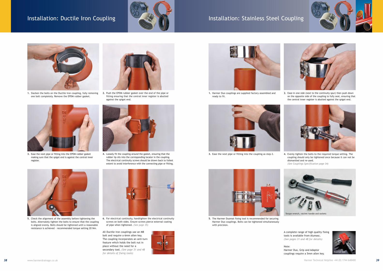
1. Slacken the bolts on the Ductile Iron coupling, fully removing
one bolt completely. Remove the EPDM rubber gasket.
2. Push the EPDM rubber gasket over the end of the pipe or
fitting ensuring that the central inner register is abutted
against the spigot end.
3. Ease the next pipe or fitting into the EPDM rubber gasket
making sure that the spigot end is against the central inner
register.
4. Loosely fit the coupling around the gasket, ensuring that the
rubber lip sits into the corresponding locator in the coupling.
The electrical continuity screws should be drawn back to fullest
extent to avoid interference with the connecting pipe or fitting.
5. Check the alignment of the assembly before tightening the
bolts. Alternately tighten the bolts to ensure that the coupling
is aligned evenly. Bolts should be tightened until a reasonable
resistance is achieved – recommended torque setting 20 Nm.
6. For electrical continuity, handtighten the electrical continuity
screws on both sides. Ensure screws pierce external coating
of pipe when tightened. (See page 35)
All Ductile iron couplings use an M8
bolt and require a 6mm allen key.
The coupling incorporates an anti-turn
feature which holds the bolt nut in
place without the need for a
secondary tool. (See page 31 and 48for details of fixing tools)
1. Harmer Duo couplings are supplied factory assembled and
ready to fit.
2. Ease-in one side (next to the continuity spur) then push down
on the opposite side of the coupling to fully seat, ensuring that
the central inner register is abutted against the spigot end.
3. Ease the next pipe or fitting into the coupling as step 2. 4. Evenly tighten the bolts to the required torque setting. The
coupling should only be tightened once because it can not be
dismantled and re-used.
(See Couplings Specification page 34)
5. The Harmer Duomat fixing tool is recommended for securing
Harmer Duo couplings. Bolts can be tightened simultaneously
with precision.
A complete range of high quality fixing
tools is available from Alumasc.
(See pages 31 and 48 for details)
Duomat tool
Torque wrench, ratchet handle and sockets
Installation: Stainless Steel Coupling
Note:
Harmer Duo, Grip and Adaptor
couplings require a 5mm allen key.
Harmer Optimal Bracket shown with Wall Plate
Stand Pipe Support Bracket
Harmer Optimal Bracket shown with Wall Plate
Stack Pipe Support Bracket shown with SML
Downpipe Support
41Harmer Technical Helpline +44 (0) 1744 648400
Installation: Vertical Pipe Support
40 www.harmerdrainage.co.uk
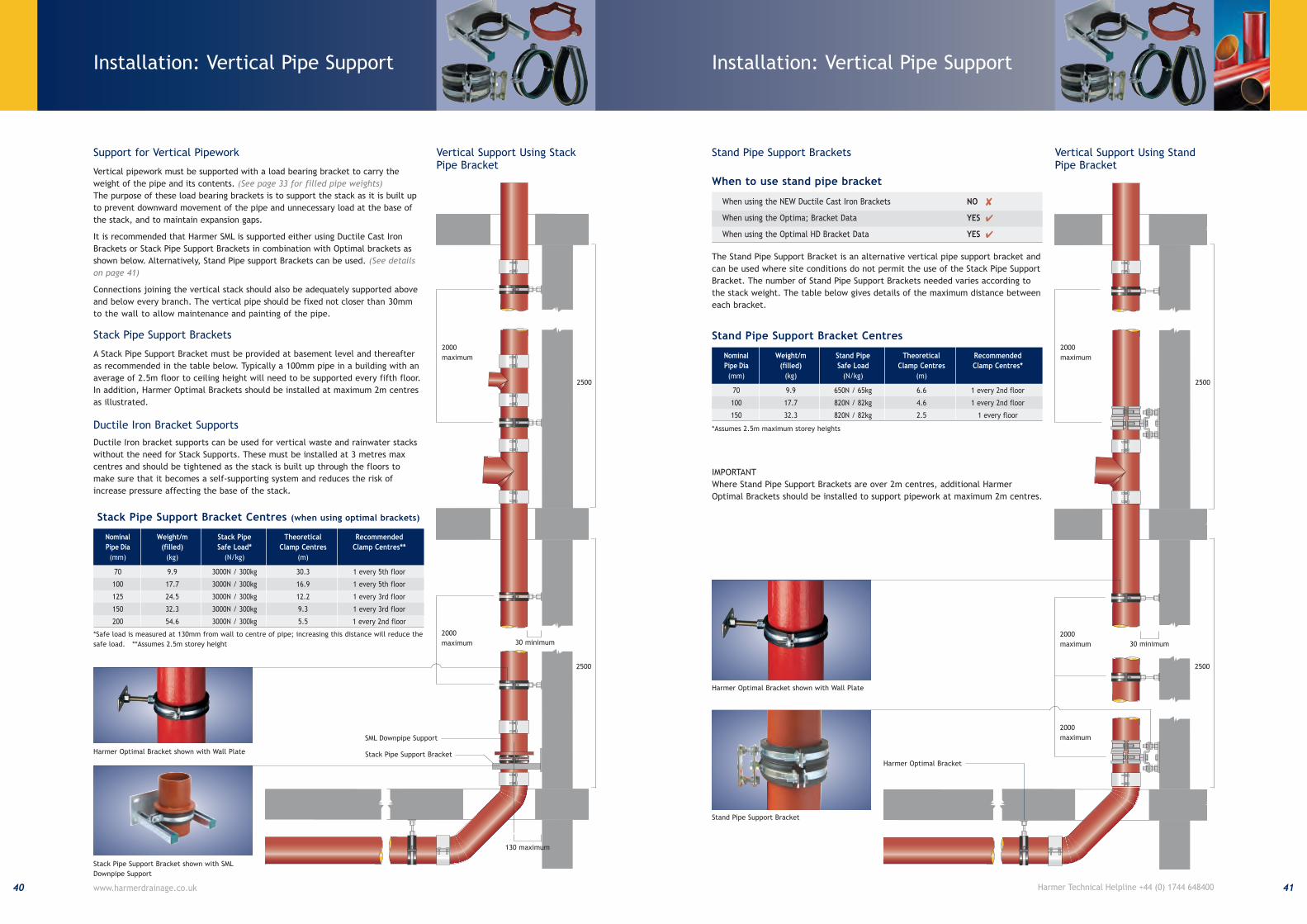
Support for Vertical Pipework
Vertical pipework must be supported with a load bearing bracket to carry the
weight of the pipe and its contents. (See page 33 for filled pipe weights)The purpose of these load bearing brackets is to support the stack as it is built up
to prevent downward movement of the pipe and unnecessary load at the base of
the stack, and to maintain expansion gaps.
It is recommended that Harmer SML is supported either using Ductile Cast Iron
Brackets or Stack Pipe Support Brackets in combination with Optimal brackets as
shown below. Alternatively, Stand Pipe support Brackets can be used. (See detailson page 41)
Connections joining the vertical stack should also be adequately supported above
and below every branch. The vertical pipe should be fixed not closer than 30mm
to the wall to allow main te nance and painting of the pipe.
Vertical Support Using StackPipe Bracket
Stack Pipe Support Brackets
A Stack Pipe Support Bracket must be provided at basement level and thereafter
as recommended in the table below. Typically a 100mm pipe in a building with an
average of 2.5m floor to ceiling height will need to be supported every fifth floor.
In addition, Harmer Optimal Brackets should be installed at maximum 2m centres
as illustrated.
Ductile Iron Bracket Supports
Ductile Iron bracket supports can be used for vertical waste and rainwater stacks
without the need for Stack Supports. These must be installed at 3 metres max
centres and should be tightened as the stack is built up through the floors to
make sure that it becomes a self-supporting system and reduces the risk of
increase pressure affecting the base of the stack.
2500
2500
2000
maximum
2000
maximum
Stand Pipe Support Brackets
The Stand Pipe Support Bracket is an alternative vertical pipe support bracket and
can be used where site conditions do not permit the use of the Stack Pipe Support
Bracket. The number of Stand Pipe Support Brackets needed varies according to
the stack weight. The table below gives details of the maximum distance between
each bracket.
IMPORTANT
Where Stand Pipe Support Brackets are over 2m centres, additional Harmer
Optimal Brackets should be installed to support pipework at maximum 2m centres.
2500
2500
2000
maximum
Harmer Optimal Bracket
2000
maximum
Stand Pipe Support Bracket Centres
Nominal Weight/m Stand Pipe Theoretical Recommended
Pipe Dia (filled) Safe Load Clamp Centres Clamp Centres*
(mm) (kg) (N/kg) (m)
70 9.9 650N / 65kg 6.6 1 every 2nd floor
100 17.7 820N / 82kg 4.6 1 every 2nd floor
150 32.3 820N / 82kg 2.5 1 every floor
Vertical Support Using StandPipe Bracket
*Assumes 2.5m maximum storey heights
30 minimum 30 minimum
2000
maximum
Stack Pipe Support Bracket Centres (when using optimal brackets)
Nominal Weight/m Stack Pipe Theoretical Recommended
Pipe Dia (filled) Safe Load* Clamp Centres Clamp Centres**
(mm) (kg) (N/kg) (m)
70 9.9 3000N / 300kg 30.3 1 every 5th floor
100 17.7 3000N / 300kg 16.9 1 every 5th floor
125 24.5 3000N / 300kg 12.2 1 every 3rd floor
150 32.3 3000N / 300kg 9.3 1 every 3rd floor
200 54.6 3000N / 300kg 5.5 1 every 2nd floor
*Safe load is measured at 130mm from wall to centre of pipe; increasing this distance will reduce the
safe load. **Assumes 2.5m storey height
130 maximum
SML Downpipe Support
Stack Pipe Support Bracket
Installation: Vertical Pipe Support
When to use stand pipe bracket
When using the NEW Ductile Cast Iron Brackets NO �
When using the Optima; Bracket Data YES �
When using the Optimal HD Bracket Data YES �
43Harmer Technical Helpline +44 (0) 1744 648400
Installation: Horizontal Pipe Support
42 www.harmerdrainage.co.uk
Support for Horizontal Pipework
Horizontal pipework should be laid to a minimum fall of 20mm per metre, and
feeder pipes should be connected to the main pipe using a 45 degree branch in the
direction of the flow. Refer to BS EN 12056-2: Code of Practice for Sanitary
Pipework for details.
It is recommended that each pipe length in a horizontal pipe run should be
supported by 2 brackets, not more than 2m apart. The length of pipe between a
bracket and a coupling should not exceed 750mm.
The pipe should be supported at every change in direction or branch. At every
10-15m, a fixing arm should be attached to a bracket to prevent pendular
movement of the pipe run. See detail below.
The requirement for pendular restraint
may be removed if the pipework has
branches entering at 45 or 90 degrees
which are supported by at least two
hangers.
(See Brackets Specification on pages 17and 18 for details of safe load weightsof brackets)
2000 maximum
Harmer Optimal Bracket
750 maximum 750 maximum
Duo Coupling
Main support
rod
Secondary rod
for lateral
support
Harmer Optimal
Bracket
Harmer SML horizontal bracket and
fixing arm
M8-M12 threaded rod
(not supplied)
See adjacent table
Harmer Optimal
HD Bracket
Alternative arrangement for pipework
with drop length over 1 metre.
Optimal HD Threaded
Bracket Rod Diameter
100 8
125 8
150 10
200 12
250 12
300 12
Threaded Rod Data
All dimensions are in mm.
Installation: Acoustic Protection
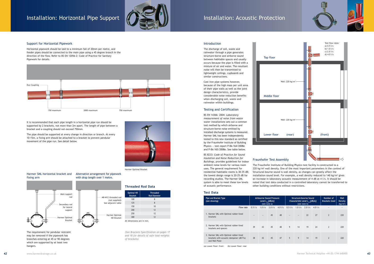
Introduction
The discharge of soil, waste and
rainwater through a pipe generates
structure-borne and airborne sound
between habitable spaces and usually
occurs because the pipe is filled with a
mixture of air and water. The resultant
noise will then be transmitted to
lightweight ceilings, cupboards and
similar constructions.
Cast iron pipe systems however,
because of the high mass per unit area
of their pipe walls as well as the joint
design characteristics, provide
considerable noise reduction benefits
when discharging soil, waste and
rainwater within buildings.
Testing and Certification
BS EN 14366: 2004: Laboratorymeasurement of noise from wastewater installations sets out a common
test method by which airborne and
structure-borne noise emitted by
installed discharge systems is measured.
Harmer SML has been independently
tested to this new standard as certified
by the Fraunhofer Institute of Building
Physics — test report P-BA 164/2008e
and P-BA 165/2008e. See table below.
BS 8233: Code of Practice for SoundInsulation and Noise Reduction forBuildings, provides guidelines for indoor
ambient noise levels for various room
uses. The general requirement for
residential/habitable rooms is 30-35 dB;
the lowest design range is 20-25 dB for
recording studios. The Harmer SML
system is able to meet these low levels
of acoustic performance.
Fraunhofer Test Assembly
The Fraunhofer Institute of Building Physics test facility is constructed to a
220 kg/m2 wall density. One of the most important parameters in the context of
Structural-bourne sound is wall density, as changes can greatly affect the
installation sound level. For example, a wall density reduced to 140 kg/m2 gives
an increase in laboratory acoustic measurement of 4 dB at 4 l/s. It should be
noted that test data conducted in a controlled laboratory cannot be transferred to
other building conditions without restrictions.
Top floor
Middle floor
Lower floor (rear) (front)
Pipe and Bracket Type Airbourne Sound Pressure Structure-bourne Sound Number of Wall
(see drawing) Level La,A
[dB(A)] Characteristic Level LSC,A
[dB(A)] Brackets Used Density
(see note a) (see note b) (kg/m2)
Flow rate 0.5 l/s 1.0 l/s 2.0 l/s 4.0 l/s 0.5 l/s 1.0 l/s 2.0 l/s 4.0 l/s — —
1. Harmer SML with Optimal rubber-lined— — 45 48 — — 22 27 2 220
brackets
2. Harmer SML with Optimal rubber-lined39 43 45 48 9 14 19 24 2 220
brackets and spacers
3. Harmer SML with Optimal rubber-lined
brackets with acoustic dampener (dB Fix) 38 43 45 47 5 9 14 19 2 220
and Wall Plate
Test Data
Test flow rates:
a) 0.5 l/s
b) 1.0 l/s
c) 2.0 l/s
d) 4.0 l/s
Wall: 220 kg/m2
(a) Lower floor: front (b) Lower floor: rear
Wall: 220 kg/m2
Installation: Connection to OtherMaterials — Rubber Joints/Boss Pipes
45Harmer Technical Helpline +44 (0) 1744 648400
Installation: Connection to Other Materials
44 www.harmerdrainage.co.uk
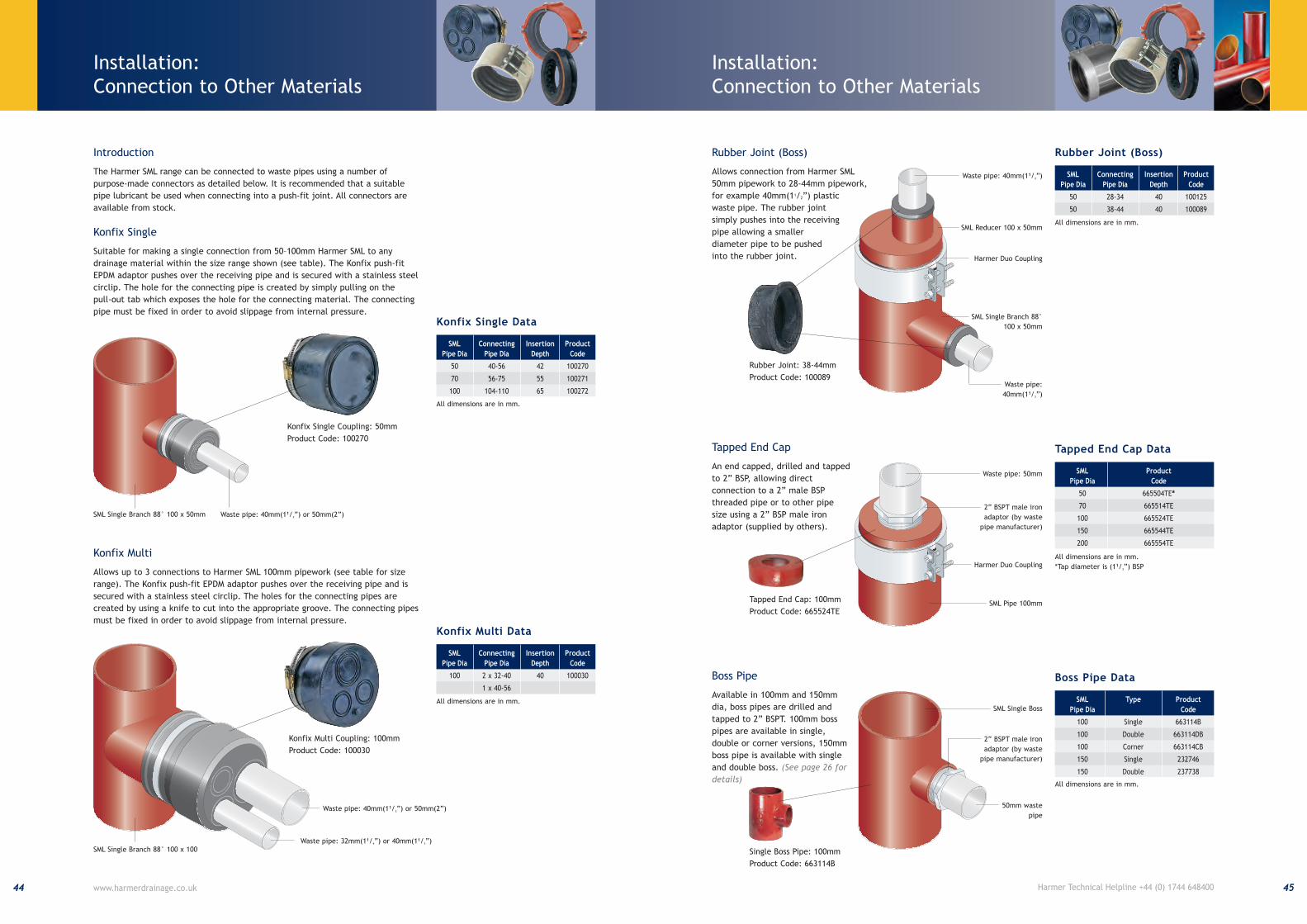
Introduction
The Harmer SML range can be connected to waste pipes using a number of
purpose-made connectors as detailed below. It is recommended that a suitable
pipe lubricant be used when connecting into a push-fit joint. All connectors are
available from stock.
Konfix Single
Suitable for making a single connection from 50–100mm Harmer SML to any
drainage material within the size range shown (see table). The Konfix push-fit
EPDM adaptor pushes over the receiving pipe and is secured with a stainless steel
circlip. The hole for the connecting pipe is created by simply pulling on the
pull-out tab which exposes the hole for the connecting material. The connecting
pipe must be fixed in order to avoid slippage from internal pressure.
Rubber Joint (Boss)
Allows connection from Harmer SML
50mm pipework to 28-44mm pipework,
for example 40mm(11/2”) plastic
waste pipe. The rubber joint
simply pushes into the receiving
pipe allowing a smaller
diameter pipe to be pushed
into the rubber joint.
Konfix Multi
Allows up to 3 connections to Harmer SML 100mm pipework (see table for size
range). The Konfix push-fit EPDM adaptor pushes over the receiving pipe and is
secured with a stainless steel circlip. The holes for the connecting pipes are
created by using a knife to cut into the appropriate groove. The connecting pipes
must be fixed in order to avoid slippage from internal pressure.
Boss Pipe
Available in 100mm and 150mm
dia, boss pipes are drilled and
tapped to 2” BSPT. 100mm boss
pipes are available in single,
double or corner versions, 150mm
boss pipe is available with single
and double boss. (See page 26 fordetails)
Tapped End Cap
An end capped, drilled and tapped
to 2” BSP, allowing direct
connection to a 2” male BSP
threaded pipe or to other pipe
size using a 2” BSP male iron
adaptor (supplied by others).
Konfix Single Coupling: 50mm
Product Code: 100270
Konfix Multi Coupling: 100mm
Product Code: 100030
Rubber Joint: 38-44mm
Product Code: 100089
SML Connecting Insertion Product
Pipe Dia Pipe Dia Depth Code
50 40-56 42 100270
70 56-75 55 100271
100 104-110 65 100272
Konfix Single Data
All dimensions are in mm.
SML Single Branch 88° 100 x 50mm Waste pipe: 40mm(11/2”) or 50mm(2”)
SML Single Branch 88° 100 x 100
Waste pipe: 40mm(11/2”) or 50mm(2”)
Waste pipe: 32mm(11/4”) or 40mm(11/2”)
50mm waste
pipe
SML Single Boss
SML Product
Pipe Dia Code
50 665504TE*
70 665514TE
100 665524TE
150 665544TE
200 665554TE
Tapped End Cap Data
All dimensions are in mm.
*Tap diameter is (11/2”) BSP
Waste pipe: 50mm
2” BSPT male iron
adaptor (by waste
pipe manufacturer)
Harmer Duo Coupling
SML Pipe 100mmTapped End Cap: 100mm
Product Code: 665524TE
2” BSPT male iron
adaptor (by waste
pipe manufacturer)
Single Boss Pipe: 100mm
Product Code: 663114B
SML Type Product
Pipe Dia Code
100 Single 663114B
100 Double 663114DB
100 Corner 663114CB
150 Single 232746
150 Double 237738
Boss Pipe Data
All dimensions are in mm.
SML Connecting Insertion Product
Pipe Dia Pipe Dia Depth Code
100 2 x 32-40 40 100030
1 x 40-56
Konfix Multi Data
All dimensions are in mm.
SML Connecting Insertion Product
Pipe Dia Pipe Dia Depth Code
50 28-34 40 100125
50 38-44 40 100089
Rubber Joint (Boss)
All dimensions are in mm.
SML Single Branch 88°
100 x 50mm
Waste pipe: 40mm(11/2”)
Waste pipe:
40mm(11/2”)
SML Reducer 100 x 50mm
Harmer Duo Coupling
Installation: Connection to Other Materials
47Harmer Technical Helpline +44 (0) 1744 648400
Installation: Manifold Connection
46 www.harmerdrainage.co.uk
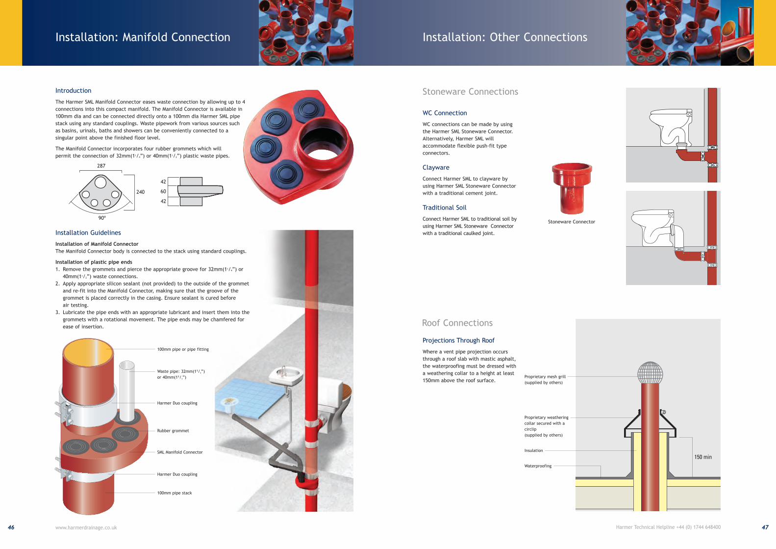
Introduction
The Harmer SML Manifold Connector eases waste connection by allowing up to 4
connections into this compact manifold. The Manifold Connector is available in
100mm dia and can be connected directly onto a 100mm dia Harmer SML pipe
stack using any standard couplings. Waste pipework from various sources such
as basins, urinals, baths and showers can be conveniently connected to a
singular point above the finished floor level.
The Manifold Connector incorporates four rubber grommets which will
permit the connection of 32mm(11/4”) or 40mm(11/2”) plastic waste pipes.
287
240
60
42
90º
42
287
240
60
42
90º
42
Installation Guidelines
Installation of Manifold Connector
The Manifold Connector body is connected to the stack using standard couplings.
Installation of plastic pipe ends
1. Remove the grommets and pierce the appropriate groove for 32mm(11/4”) or
40mm(11/2”) waste connections.
2. Apply appropriate silicon sealant (not provided) to the outside of the grommet
and re-fit into the Manifold Connector, making sure that the groove of the
grommet is placed correctly in the casing. Ensure sealant is cured before
air testing.
3. Lubricate the pipe ends with an appropriate lubricant and insert them into the
grommets with a rotational movement. The pipe ends may be chamfered for
ease of insertion.
Rubber grommet
SML Manifold Connector
Harmer Duo coupling
100mm pipe stack
Waste pipe: 32mm(11/4”)
or 40mm(11/2”)
100mm pipe or pipe fitting
Harmer Duo coupling
Proprietary mesh grill
(supplied by others)
Proprietary weathering
collar secured with a
circlip
(supplied by others)
Insulation
Waterproofing
Stoneware Connections
Roof Connections
Projections Through Roof
Where a vent pipe projection occurs
through a roof slab with mastic asphalt,
the waterproofing must be dressed with
a weathering collar to a height at least
150mm above the roof surface.
WC Connection
WC connections can be made by using
the Harmer SML Stoneware Connector.
Alternatively, Harmer SML will
accommodate flexible push-fit type
connectors.
Clayware
Connect Harmer SML to clayware by
using Harmer SML Stoneware Connector
with a traditional cement joint.
Traditional Soil
Connect Harmer SML to traditional soil by
using Harmer SML Stoneware Connector
with a traditional caulked joint.
Stoneware Connector
Installation: Other Connections
49Harmer Technical Helpline +44 (0) 1744 648400
Installation: Fixing Tools
48 www.harmerdrainage.co.uk
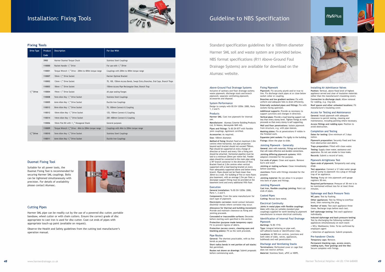
Fixing Tools
Drive Type Product Description For Use With
Code
3900 Harmer Duomat Torque Chuck Stainless Steel Couplings
110000 Rachet Handle 1/2” Drive For use with 1/
2” Drive
110001 Torque Wrench 1/2” Drive - 20Nm to 40Nm torque range Couplings with 20Nm to 40Nm torque range
110007 10mm 1/2” Drive Socket Harmer Optimal Bracket
110002 13mm 1/2” Drive Socket 70, 100, 150mm Access Bends, Swept Entry Branches, End Caps, Branch Traps
110003 18mm 1/2” Drive Socket 150mm Access Pipe Rectangular Door, Branch Trap
1/2” Drive 110004 19mm 1/
2” Drive Socket All pipe sealing flanges
110008 5mm Allen Key 1/2” Drive Socket Stainless Steel Couplings
110005 6mm Allen Key 1/2” Drive Socket Ductile Iron Couplings
110013 8mm Allen Key 1/2” Drive Socket 70, 100mm Connect-G Coupling
110012 10mm Allen Key 1/2” Drive Socket 125, 150mm Connect-G Coupling
110014 14mm Allen Key 1/2” Drive Socket 200—400mm Connect-G Coupling
110006 10mm Flat Bit with 5/16” Hexagonal Shank General purposes
110009 Torque Wrench 3/8” Drive - 4Nm to 20Nm torque range Couplings with 4Nm to 20Nm torque range
3/8” Drive 110010 5mm Allen Key 3/
8” Drive Socket Stainless Steel Couplings
110011 6mm Allen Key 3/8” Drive Socket Ductile Iron Couplings
Duomat Fixing Tool
Suitable for all power tools, the
Duomat Fixing Tool is recommended for
securing Harmer SML couplings. Bolts
can be tightened simultaneously with
precision. For details of availability
please contact Alumasc.
Cutting Pipes
Harmer SML pipe can be readily cut by the use of a powered disc cutter, portable
bandsaw, wheel cutter or with chain cutters. Ensure the correct grade of disc
appropriate to cast iron is used for disc-cutter. Coat cut ends of pipes with
appropriate touch-up paint (available on request).
Observe the Health and Safety guidelines from the cutting tool manufacturer’s
operation manual.
Guideline to NBS Specification
Above-Ground Foul Drainage SystemsInclusive of sanitary and floor drainage outlets;waste pipework; discharge stack and branchpipework; separate ventilating pipework;accessories and disposal.
System PerformanceDesign to comply with BS EN 12056: 2000, Parts1, 2 and 5.
ProductsHarmer SML: Cast iron pipework for internaluse.
Manufacturer: Alumasc Exterior Building ProductsLtd, St Helens, Merseyside WA9 4JG.
Pipes and fittings: To BS EN 877 with flexiblejoint couplings, Agrément certified.
Accessories: As required.
Size: 100mm diameter.
Method of fixing: Bracket fixed at maximum 2.0mcentres when horizontal, but pipe projectionbeyond each bracket should not exceed 750mm.Pipe should be supported at every change ofdirection or branch and every 15m a fixing armshould be attached. Horizontal pipeline must belaid to a minimum 20mm per metre fall. Feederpipes should be connected to the main pipe usinga 45º branch connector in the direction of flow.Bracket fixed at 2.0m centres when verticalsupported with a load bearing bracket at everyfloor adequately supported above and below everybranch. Pipes should not be fixed closer than30mm to a wall. For building of five or more floorsplus basement, with an average 2.5m per floor, adownpipe support fitting must be provided at thebasement level and every additional fifth floor.
ExecutionGeneral installation: To BS EN 12056: 2000,Parts 1, 2 and 5.
Components: From the same manufacturer foreach type of pipework.
Electrolytic corrosion: Avoid contact betweendissimilar metals where corrosion may occur.
Allowance for thermal and building movement:Provide and maintain clearance as fixing andjointing proceeds.
Concealed or inaccessible surfaces: Decoratebefore starting work specified in this section.
Protection (purpose made temporary caps):Fit to prevent ingress of debris.
Protection (access covers, cleaning eyes andblanking plates): Fit as the work proceeds.
Pipe RoutesGeneral: The shortest practicable, with as fewbends as possible.
Short radius bends in wet portion of soil stacks:Not permitted.
Routes not shown on drawings: Submit proposalsbefore commencing work.
Fixing PipeworkPipework: Fix securely plumb and/or true toline. Fix discharge stack pipes at or close belowsocket collar or coupling.
Branches and low gradient sections: Fix withuniform and adequate falls to drain efficiently.
Externally socketed pipes and fittings: Fix withsockets facing upstream.
Additional supports: Provide as necessary tosupport junctions and changes in direction.
Vertical pipes: Provide a load bearing support notless than every storey level. Tighten fixings as workproceeds so that every storey is self supporting.
Wall and floor penetrations: Isolate pipeworkfrom structure, e.g. with pipe sleeves.
Masking plates: Fix at penetrations if visible inthe finished work.
Expansion joint sockets: Fix rigidly to the building.
Fixings: Allow the pipe to slide.
Jointing Pipework - GenerallyGeneral: Joint with materials, fittings and techniquesthat will make effective and durable connections.
Jointing differing pipework systems: Withadaptors intended for the purpose.
Cut ends of pipes: Clean and square. Removeburrs and swarf.
Jointing or mating surfaces: Clean immediatelybefore assembly.
Junctions: Form with fittings intended for thepurpose.
Jointing material: Do not allow it to projectinto bore of pipes and fittings.
Jointing PipeworkCast iron, flexible couplings jointing: Paint cutends of pipes.
Coated PipesCutting: Recoat bare metal.
Electrical ContinuityJoints in metal pipes with flexible couplings:Make with clips (or suitable standard pipecouplings) supplied for earth bonding by pipeworkmanufacturer to ensure electrical continuity.
Identification of Internal Foul Drainage
PipeworkMarkings: To BS 1710.
Type: Integral lettering on pipe wall, self-adhesive bands or identification clips.
Locations: At 500 mm centres, junctions andboth sides of slabs, valves, appliances,bulkheads and wall penetrations.
Discharge and Ventilating StacksTerminations: Perforated cover or cage thatdoes not restrict airflow.
Material: Stainless Steel, uPVC or HDPE.
Installing Air Admittance ValvesPosition: Vertical, above flood level of highestappliance served and clear of insulation materials(other than the manufacturer's insulating cover).
Connection to discharge stack: Allow removalfor rodding, e.g. ring seal.
Roof spaces and other unheated locations: Fitmanufacturer's insulating cover.
Access for Testing and MaintenanceGeneral: Install pipework with adequateclearance to permit testing, cleaning andmaintenance, including painting where necessary.
Access fittings and rodding eyes: Position toavoid obstruction.
Completion and TestingDates for testing: Give minimum of 3 daysnotice.
Pipework preparation: Securely fixed and freefrom obstruction and debris.
Traps preparation: Filled with clean water.
Testing: Supply clean water, assistance andapparatus. Do not use smoke to trace leaks.
Records: Submit a record of tests.
Pipework Airtightness TestOpen ends of pipework: Temporarily seal usingplugs.
Test apparatus: Connect a 'U' tube water gaugeand air pump to pipework via a plug or throughtrap of an appliance.
Testing: Pump air into pipework until gaugeregisters 38 mm.
Required performance: Pressure of 38 mm is tobe maintained without loss for at least threeminutes.
Siphonage and Back Pressure TestsWC pans: Test by flushing.
Other appliances: Test by filling to overflowlevel, then removing the plug.
Number of tests: Test each appliance threetimes. Recharge traps before each test.
Self siphonage testing: Test each applianceindividually.
Induced siphonage and back pressure testing:Test by discharging the following numbers ofappliances simultaneously on each stack:
• WCs; Washbasins; Sinks: To be confirmed byemployers agent
• Selection of appliances: Submit proposals.
Pre-handover ChecksTemporary caps: Remove.
Permanent blanking caps, access covers,rodding eyes, floor gratings and the like:Secure complete with fixings.
Standard specification guidelines for a 100mm diameter
Harmer SML soil and waste system are provided below.
NBS format specifications (R11 Above-Ground Foul
Drainage Systems) are available for download on the
Alumasc website.


![A possible link between brittle and ductile failure by ... · y reproduce some basic material from [7] to set the stage for its extension for coupling brittle cracking to the ductile](https://static.fdocuments.in/doc/165x107/5f20aca154f002629072d4e2/a-possible-link-between-brittle-and-ductile-failure-by-y-reproduce-some-basic.jpg)