Installation - Bradley Corp ... Read this entire installation manual to ensure proper ... with non...
13
Installation P.O. Box 309 Menomonee Falls, WI 53052 USA 800 BRADLEY (800 272 3539) +1 262 251 6000 bradleycorp.com 215-1850 Rev. A; ECN 17-08-002 © 2017 Bradley Page 1 of 13 4/17/2017 LVAD2 Verge ® Wash Basin – LVA-Series with Evero ® Natural Quartz Material Table of Contents Components .................................................................. 3–4 Supplies Required ............................................................. 5 Dimensions .................................................................... 5–6 Rough-Ins ....................................................................... 7-8 Overflow Plug Assembly .................................................... 9 Drain Assembly ................................................................. 9 Faucets and Optional Soap Valve ................................... 10 Bowl Mounting ................................................................. 10 Strainer and P-trap .......................................................... 11 Adjust Temperature.......................................................... 11 Access Panel ................................................................... 12 Cleaning and Maintenance.............................................. 13
Transcript of Installation - Bradley Corp ... Read this entire installation manual to ensure proper ... with non...

Installation
P.O. Box 309Menomonee Falls, WI 53052 USA
800 BRADLEY (800 272 3539)+1 262 251 6000bradleycorp.com
215-1850 Rev. A; ECN 17-08-002© 2017 BradleyPage 1 of 13 4/17/2017
LVAD2Verge® Wash Basin – LVA-Series with Evero® Natural Quartz Material
Table of ContentsComponents ..................................................................3–4Supplies Required .............................................................5Dimensions ....................................................................5–6Rough-Ins .......................................................................7-8Overflow Plug Assembly ....................................................9Drain Assembly .................................................................9Faucets and Optional Soap Valve ...................................10Bowl Mounting .................................................................10Strainer and P-trap ..........................................................11Adjust Temperature ..........................................................11Access Panel ...................................................................12Cleaning and Maintenance ..............................................13

LVAD2 Installation
2 4/17/2017 Bradley • 215-1850 Rev. A; ECN 17-08-002
WARNINGMake sure that all water supply lines have been flushed and then completely turned off before beginning installation. Debris in supply lines can cause valves to malfunction.
Turn OFF electrical power to the electrical outlets, then unplug all electrical units prior to installation. Electrical power MUST remain off until installation is complete.
Installer's hardware must be appropriate for wall construction. Wall anchors must have a minimum pull-out rating of 1,000 pounds.
IMPORTANTRead this entire installation manual to ensure proper installation. When finished with the installation, file this manual with the owner or maintenance department. Compliance and conformity to local codes and ordinances is the responsibility of the installer. Product warranties may be found under “Products” on our Web site at www.bradleycorp.com.
Separate parts from packaging and make sure all parts are accounted for before discarding any packaging material. If any parts are missing, do not begin installation until you obtain the missing parts.
For standard height mounting, do not exceed the recommended 33.5" distance from the fixture rim to the finished floor.

Installation LVAD2
Bradley • 215-1850 Rev. A; ECN 17-08-002 4/17/2017 3
Components
LVAD2BOContact your Bradley
Representative for color options
Individual Rough-In OptionChrome P-trap (S29-094)Plastic P-trap (269-1697)
O-Ring (125-111)
Drain Adapter
Packing Washer
#10-24 Screw
Drain Adapter Prepack
(S45-2480)
Access Panel (186-1912)
Wall Bracket (140-1128)
Drain Cap (111-140)
Drain Cap Spacer (269-2540)
Trough Strainer (173-039)
Trough Strainer Screw(160-353)
Access Panel Bracket (140-1172)
#10 Access Panel Thumb Screw
(160-536)Access Panel Security
Screw Option (S45-2880)
TMV Valve (1/2" NPTM
Outlet) (S45-2701)
Hose Prepack (S45-2730)
Supply Fittings
(S45-2510)
TMV Supply Connections
Plastic Hose Supply Fittings
(S45-2511)
Hose Prepack (S45-2731)
Tempered Supply Connections
Plastic Hose
Plastic Hose
Stainless Steel Hose
LVAD2 Installation
4 4/17/2017 Bradley • 215-1850 Rev. A; ECN 17-08-002
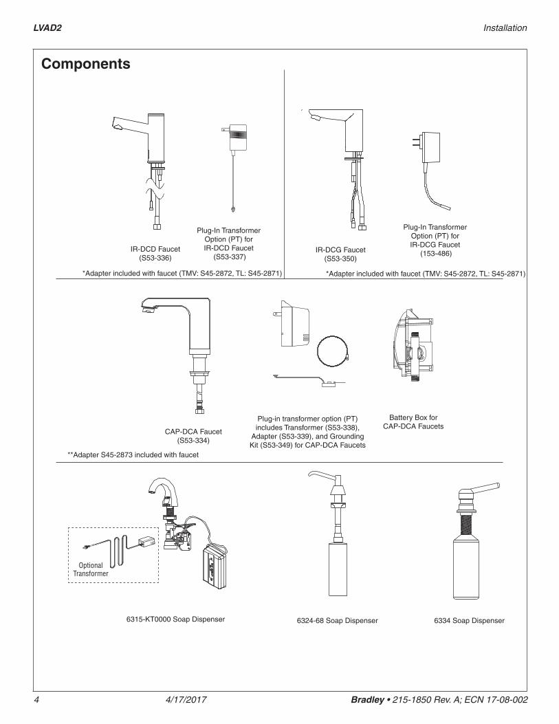
Components
IR-DCD Faucet (S53-336)
CAP-DCA Faucet (S53-334)
Battery Box for CAP-DCA Faucets
6315-KT0000 Soap Dispenser 6324-68 Soap Dispenser 6334 Soap Dispenser
Optional Transformer
Plug-In Transformer Option (PT) for IR-DCD Faucet
(S53-337)
Plug-in transformer option (PT) includes Transformer (S53-338),
Adapter (S53-339), and Grounding Kit (S53-349) for CAP-DCA Faucets
IR-DCG Faucet (S53-350)
Plug-In Transformer Option (PT) for IR-DCG Faucet
(153-486)
*Adapter included with faucet (TMV: S45-2872, TL: S45-2871) *Adapter included with faucet (TMV: S45-2872, TL: S45-2871)
**Adapter S45-2873 included with faucet

Installation LVAD2
Bradley • 215-1850 Rev. A; ECN 17-08-002 4/17/2017 5
DimensionsTop View (shown with CAP-DCA faucet and 6315 soap)
Front View
Supplies Required• (6) ³⁄₈" fasteners and wall anchors for bowl and wall bracket (minimum pull-out rating of 1,000 lbs.)
• (4) ¼" fasteners and wall anchors for access panel brackets (minimum pull-out rating of 100 lbs.)
• ½" hot/cold or tempered stub-out
• 1½" NPT drain stub-out(s)
• OPTIONAL: (2) 110 volt GFCI protected electrical outlets for 100–120 VAC plug-in transformers only
• Screen filter(s) as needed, if not included with faucet(s)
• Drill
• Crescent wrench
• Tape Measure
14-3/8" (366mm)
21" (533mm)
5" (127mm) 6"
(152mm)
1-5/8" (40mm)
2-1/2" (64mm)
50" (1270mm)
59-3/4" (1518mm)
20" (509mm)
3-3/4" (95mm)
56-7/8" (1444mm)
60" (1524mm)
• Phillips screw driver
• Flat head screw driver
• Level
6" (152mm)
15" (381mm)
15" (381mm)

LVAD2 Installation
6 4/17/2017 Bradley • 215-1850 Rev. A; ECN 17-08-002
Dimensions – Side View
A
B
14" (357mm)
3-3/4" (95mm)
C
20" (508mm)
21" (534mm)
20°
7-1/2" (190mm)
7-1/2" (191mm)
2" (50mm)
ADA/TAS Standard Height
ADA/TAS Juvenile Height (Children 6-12 years)
CSA Standard Height
Dim A 33-1/2" (851mm) 30-1/2" (775mm) 33-1/2" (851mm)
Dim B 27" (686mm) 24" (610mm) 29-29/32" (760mm)
Dim C 13-1/2" (343mm) 10-1/2" (267mm) 13-1/2" (536mm)

Installation LVAD2
Bradley • 215-1850 Rev. A; ECN 17-08-002 4/17/2017 7
Mounting for Standard, ADA and TAS height shown.
Structural Rough-Ins
Points A, B and C require sufficient backing compliant with local building codes.
WARNING Ensure bowl is completely seated in the wall bracket and securely fastened to the wall at point A.
(mm)
AA
BB
CL
CODE DESCRIPTION QTY.A Install (1) 3/8" wall anchor with a minimum pull-out force of 1,000 lbs. per local codes at locations shown 2
B Provide structural backing compliant with local building codes. 2
C Install wall anchor with a minimum pull-out force of 100 lbs. per local codes at locations shown 4
Wall Bracket
RIM HEIGHT VERTICAL HEIGHT ADJUSTMENTS FIXTURE STYLE33½" No Adjustment Standard Height, ADA, TAS and CSA
30½" Subtract 3" Juvenile, ADA and TAS
CC
28-1/8" (723)
Bottom of
Bracket
33-1/2" (851)
24-1/8" (612)
13-1/8" (333)
27-5/8" (701)
27-5/8" (701)
24-1/8" (612)
3/4" (19)
36-1/2" (927)
25" (635) 25" (635)
25-1/4" (640)
Secure bracket to wall using min. (2) 3/8" anchor bolts to the left of C/L and min. (2) 3/8" anchor bolts to the right
of C/L. The (2) anchor bolts to the right of C/L must be min. 16" apart from the anchor bolts to the left of C/L. When
mounting is complete, check to ensure the bracket is level. See Step 1: Bracket
Mounting for more information.
31-1/2" (800)

LVAD2 Installation
8 4/17/2017 Bradley • 215-1850 Rev. A; ECN 17-08-002
Plumbing and Electrical Rough-Ins
Mounting for Standard, ADA and TAS height shown.
(mm)
33-1/2" (851)
24-1/8" (613)
17-1/2" (444) Min
AE
H C
CL
2-1/4" (57)
1" (25)
Finished Floor
25" (635)4-1/2" (114)
E
CODE DESCRIPTION QTY.A 1½" NPT Drain, Stub-out 2" from wall 1
H,C ½" Nominal (⁵⁄₈" O.D. Comp.) Hot/Cold supplies, Stub-out 2" from wall 1
E 110V GFI protected electrical outlet 2

Installation LVAD2
Bradley • 215-1850 Rev. A; ECN 17-08-002 4/17/2017 9
Bracket Mounting
Typical installation is shown. It may be necessary to repair the wall after mounting. The fixture may not cover all of the wall modifications.
1
Mounting height per structural rough-in dimensions.
For ease of drain installation, lay the bowl on its back.
2 Drain Assembly
Install wall bracket to wall per structural rough-in dimensions. Check to ensure the bracket is level. Example anchor locations shown.
A
CL
16" (406mm)
min.
O-Ring
Drain Adapter
Packing Washer
#10-24 Screw
Assemble the remaining components as shown and thread the four screws through the drain adapter and into the basin inserts. Ensure the screws compress the drain adapter evenly onto the basin.
A

LVAD2 Installation
10 4/17/2017 Bradley • 215-1850 Rev. A; ECN 17-08-002
Bowl Mounting (to Bracket and Wall)4
Faucet Installation3For ease of drain installation, lay the bowl on its back.
Install the faucets and optional soap valves according to the manufacturer's instructions.A
Position bowl above wall bracket. Press firmly on the back of the bowl to seat the bowl flange into the wall bracket lip. Ensure bowl is level.
ASecure the bowl to the wall anchors using fasteners per the structural rough-in requirement (supplied by installer).
B
WARNING Ensure bowl is completely seated in the wall bracket and securely fastened to the wall at point A.
CAUTION Bracket is not intended to support the weight of bowl for an extended period of time. Be sure to secure the bowl to the wall using appropriate fasteners.
Other basin models may be shown for faucet mounting visual.
CAUTION Positioning bowl onto bracket may require two people.

Installation LVAD2
Bradley • 215-1850 Rev. A; ECN 17-08-002 4/17/2017 11
Adjust Temperature with Water Running
H C
ALoosen Cap Screw about 1/4" (4-6 turns) and lift up cover (do not remove).
BUsing cover, turn cartridge gently until desired water temperature is reached. Do not turn past stops as this may damage unit. Push cover down and tighten screw.
WARNING This valve is NOT factory preset. Upon installation, the temperature of this valve must be checked and adjusted to ensure delivery of a safe water temperature. Water in excess of 110°F (43°C) may cause scalding.
6
1 station shown, 2 station similar.Strainer and Drain Cap5
Position drain cap over trough strainer, aligning tabs into drain. Push drain cap down until drain cap is flush with basin. Grommets should hold drain cap securely against drain tough walls.
A
To remove drain cap, carefully slip flat screwdriver into left or right hand corner of drain cap and gently lift upwards.
B
Faucet and soap removed for clarity.
Front
Note Angle of Drain Cap
Drain cap is labeled front and back. Be sure front is facing the user. Top surface of drain cap should be sloped away from user.

LVAD2 Installation
12 4/17/2017 Bradley • 215-1850 Rev. A; ECN 17-08-002
Install access panel brackets to wall using #10 fasteners (supplied by installer) as shown in rough in drawing. Install top screw into slot. Do not install bottom screw until Step C is complete.
A
Make all connections before installing access panel.
Access Panel7
#10 Top Screw
Shown in closed position. Rotate
90° to Open
Insert #10 thumbscrews into front bowl apron as shown. Thumbscrew in vertical position is closed. Thumbscrew in horizontal position is open.
B
Hang access panel onto mounting brackets attached to wall on the left and right sides. Rotate panel up and check fitup between thumbscrews and panel slots. Rotate access panel down and make adjustment to brackets if necessary. Install bottom #10 fastener into brackets.
C
Rotate access panel up and secure by rotating thumbscrews to the closed position
ETo open access panel, rotate thumb screw, slightly push panel up and swing access panel down. Do not remove thumbscrews.
F
#10 Thumb Screw
CAUTION For applications where children are present or for applications subject to vandalism, order security screw option S45-2880.
Attach P-trap to drain adapter and waste outlet.D

Installation LVAD2
Bradley • 215-1850 Rev. A; ECN 17-08-002 4/17/2017 13
Cleaning and Maintenance for EveroMaterial Description: Evero Natural Quartz Material is made of bio-based resin, natural quartz and other materials to resist chemicals, stains, burns and impact. Variations in the natural stone color, pattern, size, shape and shade are inherent. Due to these unique characteristics, please expect subtle shade variations when units are installed adjacent to each other.
Routine Cleaning: For regular cleaning, use mild neutral base cleaners.
Stubborn Stains: Remove tough stains, with non abrasive cleaners and pads such as a white Scotch Brite® pad or Magic Eraser. Test on inconspicuous area prior to using the suggested products.
Protecting the Surface: To optimize material performance in high use areas, it is recommended to apply DryTreat Stain-Proof Original or equivalent as needed.
Repair Kits: Evero repair kits are available. Contact your Bradley representative or distributor for part numbers and pricing. Repair kits are made to order and have a shelf life of 30 days.
NOTICE! Do not use strong acid or alkaline chemicals and cleansers to clean Evero. If these chemicals come in contact with the surface, wipe them off immediately and rinse with soapy water. Avoid contact with harsh chemicals such as paint remover, bleach, acetone, chloride based cleaners, floor cleaners, etc. Avoid contact with hot pans and objects.
Cleaning and maintenance instructions for stainless steelMaterial Description: Stainless steel is extremely durable, and maintenance is simple and inexpensive. Proper care, particularly under corrosive conditions, is essential. Always start with the simplest solution and work your way toward the more complicated.
Routine cleaning: Daily or as often as needed use a solution of warm water and soap, detergent, or ammonia. Apply the cleaning solution per the manufacturer’s instructions and always use a soft cloth or sponge to avoid damaging the finish.
Stubborn Stains: To remove stains from stainless steel use a stainless steel cleaner and polish such as Ball® stainless steel cleaner or a soft abrasive. Always follow the manufacturer’s instructions and apply in the same direction as the polish lines.
NOTICE! Never use ordinary steel wool or steel brushes on stainless steel. Always use stainless steel wool or stainless steel brushes.
Special Situations for Material
Fingerprints and Smears: To remove fingerprints or smears use a high quality stainless steel cleaner and polish in accordance with the manufacturer’s instructions. Many of these products leave a protective coating that helps prevent future smears and fingerprints.
Grease and Oil : To remove grease and oil use a quality commercial detergent or caustic cleaner. Apply in accordance to the manufacturer’s instructions and in the direction of the polish lines.
Precautions: Avoid prolonged contact with chlorides (bleaches, salts), bromides (sanitizing agents), thiocyanates (pesticides, photography chemicals, and some foods), and iodides on stainless steel equipment, especially if acid conditions exist.
NOTICE! Do not permit salty solutions to evaporate and dry on stainless steel.
The appearance of rust streaks on stainless steel leads to the belief that the stainless steel is rusting. Look for the actual source of the rust in some iron or steel particles which may be touching, but not actually a part of the stainless steel structure.
NOTICE! Strongly acidic or caustic cleaners may attack the steel, causing a reddish film to appear. The use of these cleaners should be avoided.
Brand Names: Use of brand names is intended only to indicate a type of cleaner. This does not constitute an endorsement, nor does the omission of any brand name cleaner imply its inadequacy. Many products named are regional in distribution, and can be found in local supermarkets, department and hardware stores, or through your cleaning service. It is emphasized that all products should be used in strict accordance with package instructions.