Installation - Bradley Corp · Leave the protective masking on until installation is complete. ......
33
Installation P.O. Box 309 Menomonee Falls, WI 53052 USA 800 BRADLEY (800 272 3539) +1 262 251 6000 bradleycorp.com HDWP-INSTR-013 Rev. L; ECN 12-14-015G © 2018 Bradley Page 1 of 33 3/23/2018 Bradmar ™ Restroom Partitions Overhead Braced - Series 400 (includes No-Site style) Table of Contents Pre-Installation Information 2-3 Layout Dimensions for Brackets 4 Mounting Brackets to Wall 5-6 Leveling Screws to Pilaster 6 Mounting Brackets to Pilasters 7–8 Pilaster Mounting Hardware 8 Pilasters and Panels 9–11 Pilaster Shoes 12 Headrail 13 Hinges 14–21 Door Hardware 22–29 Stiffener Bracket 30 Urinal Screens 31–33 For Standard Height Doors and Panels Only *HDWP-INSTR-013*
Transcript of Installation - Bradley Corp · Leave the protective masking on until installation is complete. ......

Installation
P.O. Box 309Menomonee Falls, WI 53052 USA
800 BRADLEY (800 272 3539)+1 262 251 6000bradleycorp.com
HDWP-INSTR-013 Rev. L; ECN 12-14-015G© 2018 BradleyPage 1 of 33 3/23/2018
Bradmar™ Restroom Partitions Overhead Braced - Series 400 (includes No-Site style)
Table of ContentsPre-Installation Information . . . . . . . . . . . . . . . . . . 2-3Layout Dimensions for Brackets . . . . . . . . . . . . . . . . 4Mounting Brackets to Wall . . . . . . . . . . . . . . . . . . . 5-6Leveling Screws to Pilaster . . . . . . . . . . . . . . . . . . . . 6Mounting Brackets to Pilasters . . . . . . . . . . . . . . . 7–8Pilaster Mounting Hardware . . . . . . . . . . . . . . . . . . . 8Pilasters and Panels . . . . . . . . . . . . . . . . . . . . . . 9–11Pilaster Shoes . . . . . . . . . . . . . . . . . . . . . . . . . . . . . 12Headrail . . . . . . . . . . . . . . . . . . . . . . . . . . . . . . . . . . 13Hinges . . . . . . . . . . . . . . . . . . . . . . . . . . . . . . . . 14–21Door Hardware . . . . . . . . . . . . . . . . . . . . . . . . . . 22–29Stiffener Bracket . . . . . . . . . . . . . . . . . . . . . . . . . . . . 30Urinal Screens . . . . . . . . . . . . . . . . . . . . . . . . . . 31–33
For Standard Height Doors and Panels Only
*HDWP-INSTR-013*

2
Bradmar™ Restroom Partitions, Floor-Mounted with Overhead Brace — Series 400 Installation
3/23/2018 Bradley • HDWP-INSTR-013 Rev. L; ECN 12-14-015G
WARNINGBefore beginning installation, make sure that the wall and floor backing are adequate to support the secure mounting of the toilet compartment units.
Partitions are extremely heavy and may require more than one person to position and install.
Failure to comply with these instructions may result in personal injury and/or property damage and will void the partition warranty.
CAUTIONPersonal protective equipment (PPE) is required during the installation and maintenance of this product.
NOTICELeave the protective masking on until installation is complete. To prevent warping, always lay the material flat. Do not lean the material against the wall or stack unevenly. Allow 24 hours for material to adjust to site environment. Partitions should be installed in a climate-controlled environment and shielded from direct sunlight.
Make sure all floors and walls are clean and smooth. Remove loose impediments, such as protruding nails and other debris which could affect installation.
Use caution when drilling. Accuracy is important.
Carefully remove components from skid, do not drag.
IMPORTANTReview your partition layout drawings and verify the number of stalls and components before beginning installation.
Read this installation manual completely to ensure proper installation, then file it with the owner or maintenance department. This installation manual provides instruction for the assembly of normal partition configurations and standard components. Non-standard configurations or components including but not limited to curved or angled walls, partial walls, oversized panels, or modified hardware are not covered in this manual. Compliance and conformity to local codes and ordinances is the responsibility of the installer.
Separate parts from packaging and make sure all parts are accounted for before discarding packaging material. If any parts are missing, do not begin installation until you obtain the missing parts.
Product warranties and parts information may be found under "Products" on Bradley's website at bradleycorp.com.

3
Installation Bradmar™ Restroom Partitions, Floor-Mounted with Overhead Brace — Series 400
Bradley • HDWP-INSTR-013 Rev. L; ECN 12-14-015G 3/23/2018
Supplies Required:
Hardware Provided
#14 x 2" Button-Head
Sheet Metal Screw TORX-T27 Drive
FAST-P002
#14-16 Plastic Anchor
FAST-T373
#8 x 1" Flat Head
Sheet Metal Screw Phillips Drive FAST-P006
#10-24 x 2" Flat Head
Machine Screw TORX-T25 Drive
FAST-S0027
9/32" x 5/8" Flat Washer
P10-449
Example of Submittal Drawing
• Chalk line and pencil• Flat blade and Phillips head screwdrivers• Jigsaw or hacksaw• Circular saw• Two spring clamps• 3/32", 7/64", 1/8", 5/32", 13/64", 7/32" and 1/4"
dill bits
• Power drill or screw gun with drill bit extension• Tape measure and 4' level• 5/16" ceramic tile and masonry drill bit• Hammer drill• Spacer, 14" (356mm) high and strong enough to
support the panel
#10-24 x 3/4" Button-Head Barrel Nut
TORX-T27 Drive FAST-P003
#10 x 3/4" Flat Head
Sheet Metal Screw TORX-T25 Drive
FAST-S0006
#6 x 3/4" Phillips Flat-Head
Sheet Metal Screw FAST-P011
#10 x 3/4" Button-Head
Sheet Metal Screw TORX-T25 Drive
FAST-P005
#10-24 x 3/4" Button-Head
Shoulder Screw TORX-T27 Drive
FAST-P004
60-1/2"(1537mm) Wall to Center
Line
61-1/4" (1556mm)
to Face
36"(914mm) Center to Center
1"(25mm) Gap
1/2"(13mm) Gap
1"(25mm) Gap
7" (178mm)
26" (660mm)
24" (610mm)
19-1/2"4 4-1/
2"
5-1/
2"
1-1/
2"
58-3
/4"
(149
2mm
)
58-3
/4"
(149
2mm
)
36" (914mm)
4" (102mm)
#14 x 5/8" Button-Head
Sheet Metal Screw TORX-T27 Drive
FAST-S0016
#10 x 5/8" Button-Head
Sheet Metal Screw Torx-T27 DriveFAST-S0019
#14 x 3/4" Button-Head
Sheet Metal Screw TORX-T27 Drive
FAST-P001
5/16" x 1-1/2" Hex Head Lag Screw FAST-S008
4
Bradmar™ Restroom Partitions, Floor-Mounted with Overhead Brace — Series 400 Installation
3/23/2018 Bradley • HDWP-INSTR-013 Rev. L; ECN 12-14-015G
*
**
* *
**
*
*
Pilaster Plumb Line
When installing the partition components, consult the applicable Mills Partition submittal drawing for compartment layout dimensions.
1a Layout Dimensions - Stirrup Brackets (Optional)
Pilaster Centerline: Measure from the back wall forward to the face of the compartment, subtract 1/2" (13mm) and mark this location on the floor ("A") . Mark the same measurement on the opposite end of your layout ("A1") and draw a straight line connecting both marks .
For Freestanding (FS) Partitions: Refer to submittal drawings and determine the approximate location of the outside panels . Establish dimensions "A" and "A1" as explained above .
A
Panel Centerline: Measure the stall width across the back wall and place a mark at the base of the rear wall ("B") . Repeat this step for each panel, starting each measurement from the last panel centerline ("B1") .
B
Draw a plumb line on all walls from each pilaster and panel centerline . From the highest point in the room, measure 20" (508mm), 41-1/2" (1054mm), and 63" (1600mm) from the floor and place a mark on the pilaster/panel plumb line . These marks represent the hole center line of the stirrup brackets . Use a level to transfer that mark to all other plumb lines ("C") .
C
Panel plumb line
63" (1600mm)
41-1/2" (1054mm)
"A""B"
"B1"
"A1"
"C""C"
"C""C"
"C"
"C""C"
"C"
"C"
20" (508mm)
CL
CLCL
CL
CL
CL
CL
CL CLCLPilaster
Plumb Line
When installing the partition components, consult the applicable Mills Partition submittal drawing for compartment layout dimensions.
1 Layout Dimensions - Continuous Brackets (Standard)
Pilaster Centerline: Measure from the back wall forward to the face of the compartment, subtract 1/2" (13mm) and mark this location on the floor ("A") . Mark the same measurement on the opposite end of your layout ("A1") and draw a straight line connecting both marks .
For Freestanding (FS) Partitions: Refer to submittal drawings and determine the approximate location of the outside panels . Establish dimensions "A" and "A1" as explained above .
A
Panel Centerline: Measure the stall width across the back wall and place a mark at the base of the rear wall ("B") . Repeat this step for each panel, starting each measurement from the last panel centerline ("B1") .
B
Draw a plumb line on all walls from each pilaster and panel centerline . From the highest point in the room, measure 14-1/2" (369mm) from the floor and place a mark on the pilaster/panel plumb line . Use a level to transfer that mark to all other plumb lines ("C") .
C
Panel plumb
line
"C""C"
"C"
"A" "B"
"B1"
"A1"
*
*
*
14-1/2" (369mm) To bottom of
bracket (highest point in floor)

5
Installation Bradmar™ Restroom Partitions, Floor-Mounted with Overhead Brace — Series 400
Bradley • HDWP-INSTR-013 Rev. L; ECN 12-14-015G 3/23/2018
2a Continuous Aluminum Brackets to Wall (Optional)
established level line
pila
ster
/pan
el
plum
b lin
e
floor
CL
Place the bottom of each continuous bracket at the established level line . Center the bracket opening on the pilaster/panel plumb line .
A
Insert the plastic anchors in all holes and secure the brackets to the wall with the #14 x 2" screws provided .C
Single "EAR" bracket is shown here; single "EAR" brackets are for end panels and pilasters; double "EAR" brackets are for dividing panels.
Using the bracket as a template, mark the hole locations on the wall . Remove the bracket and drill a Ø5/16" hole (min . 2" [51mm] deep) at each hole location .
B
On end panel and pilaster applications, position the bracket with the ear facing toward the inside of the stall.
One-Eared Bracket
Two-Eared Bracket
2 Continuous Stainless Steel Brackets to Wall (Standard)
established level line
pila
ster
plu
mb
line
floor
CL
Place the bottom of each continuous bracket at the established level line . Center the bracket opening on the pilaster/panel plumb line .
A
Insert the plastic anchors in all holes and secure the brackets to the wall with the #14 x 2" screws provided .C
On pilaster applications, position the bracket with the ear facing toward the inside of the stall.
Using the bracket as a template, mark the hole locations on the wall . Remove the bracket and drill a Ø5/16" hole (min . 2" [51mm] deep) at each hole location .
B
Brackets are used as templates, but since the hole patterns may be different, the brackets may not be interchangeable.
Pilaster bracket is shown here; "Ear" brackets are for pilasters, and "U" brackets are for panels.
"Ear" Bracket
"U" Bracket
Brackets are used as templates, but since the hole patterns may be different, the brackets may not be interchangeable.

6
Bradmar™ Restroom Partitions, Floor-Mounted with Overhead Brace — Series 400 Installation
3/23/2018 Bradley • HDWP-INSTR-013 Rev. L; ECN 12-14-015G
3 Leveling Screws to Pilaster
2b Stirrup Brackets to Wall (Optional)
established level line
pila
ster
/pan
el p
lum
b lin
e
floor
CL
Place the center of each stirrup bracket at the established level line . Center the bracket opening on the pilaster/panel plumb line .
A
Insert the plastic anchors in all holes and secure the brackets to the wall with the #14 x 2" screws provided .C
Single "EAR" bracket is shown here; single "EAR" brackets are for end panels and pilasters; double "EAR" brackets are for dividing panels.
Using the bracket as a template, mark the hole locations on the wall . Remove the bracket and drill a Ø5/16" hole (min . 2" [51mm] deep) at each hole location .
B
One-Eared Bracket
Two-Eared Bracket
On end panel and pilaster applications, position the bracket with the ear facing toward the inside of the stall.
4" - 16" Pilaster: Center and drill a Ø13/64" pilot hole, 1-1/2" (38mm) deep .
18" - 24" Pilaster: Drill (2) Ø13/64" pilot holes, 1-1/2" (38mm) deep . Holes should be 2" (51mm) off each end of the pilaster .
A
For integral hinge and no-site pilasters, a notch will be present on one end of the pilaster to indicate that it is the bottom.
Use leveling screw(s) to adjust height of pilaster as indicated based on pilaster width .B
4" - 16" Pilaster
18" - 24" Pilaster

7
Installation Bradmar™ Restroom Partitions, Floor-Mounted with Overhead Brace — Series 400
Bradley • HDWP-INSTR-013 Rev. L; ECN 12-14-015G 3/23/2018
4 Continuous Brackets to Pilaster (Standard)
Refer to the submittal drawing to locate the split dimension and layout location of each marked pilaster.
Measure 13-1/2" (343mm) and 67-1/2" (1715mm) down from the top of each pilaster and place a mark on the pilaster split centerline .
A
Secure the continuous bracket to the pilaster using the #14 x 3/4" screws provided .C
Split
Split67-1/2"
(1715mm)
Place the continuous bracket between each established level line . Center the bracket opening on the pilaster split centerline . Using the bracket as a template, mark the hole locations on the pilaster . Remove the bracket and drill a Ø7/32" pilot hole, 3/4" (19mm) deep at each location .
B
Brackets are used as templates, but since the hole patterns may be different, the brackets may not be interchangeable.
Continuous stainless steel bracket shown.Pilaster shown is for reference only. Actual pilaster varies depending on application.
13-1/2" (343mm)
4a Stirrup Brackets to Pilaster (Optional)
Refer to the submittal drawing to locate the split dimension and layout location of each marked pilaster. Measure 19" (483mm), 40-1/2" (1029mm), and 62" (1575mm)
down from the top of each pilaster and place a mark on the pilaster split centerline .A
Split
Split
19" (483mm)
40-1/2" (1029mm)
Place stirrup brackets at each established level line . Center the bracket opening on the pilaster split centerline . Using the bracket as a template, mark the hole locations on the pilaster . Remove the bracket and drill a Ø7/32" pilot hole, 3/4" (19mm) deep at each location .
B
Secure the stirrup brackets to the pilasters using the #14 x 3/4" screws provided .C
Pilaster shown is for reference only. Actual pilaster varies depending on application.
62" (1575mm)
CL
CL

8
Bradmar™ Restroom Partitions, Floor-Mounted with Overhead Brace — Series 400 Installation
3/23/2018 Bradley • HDWP-INSTR-013 Rev. L; ECN 12-14-015G
4b Alcove Brackets to Pilaster
Layouts that use stirrup brackets for pilaster and panel connections will use continuous alcove brackets.
Refer to the submittal drawing for the layout location of each alcove pilaster
Measure 13-1/2" (343mm) and 67-1/2" (1715mm) down from the top of each pilaster and place a mark on the side of the pilaster .
ACenter the bracket between each mark made in Step A and push tight against side of pilaster .BUsing the bracket as a template, mark the hole locations on the pilaster . Remove the bracket and drill Ø1/4" holes through the pilaster at each location .
CSecure the bracket to the pilaster using the #10-24 x 3/4" barrel nuts and #10-24 x 3/4" shoulder screws provided .
D
67-1/2" (1715mm)
13-1/2" (343mm)
Continuous stainless steel bracket shown
5 Pilaster Mounting Hardware
Starting with the pilaster closest to the wall, measure and mark the pilaster and door widths on the pilaster centerlineline . Make sure to leave the appropriate gap between the wall and the pilaster . Place the corresponding shoe on the pilaster centerline and center between the marks .A
Insert plastic anchors into the holes and secure the shoe to the anchors using the 9/32" x 5/8" flat washer and #14 x 2" screws provided .
C
Using the shoe as a template, mark the hole locations on the floor . Remove the shoe and drill Ø5/16" holes (min 2" (51mm) deep) into the floor . Make sure the holes are free of dirt and debris .
B
36" (914mm)
Pilaster Centerline
24" (610mm)
4" (102mm)
7" (178mm)
26" (660mm)
This view is an example only; refer to your submittal drawings for actual sizes.
1" (25mm) Gap

9
Installation Bradmar™ Restroom Partitions, Floor-Mounted with Overhead Brace — Series 400
Bradley • HDWP-INSTR-013 Rev. L; ECN 12-14-015G 3/23/2018
6 Pilasters and Panels with Stainless Steel Continuous Brackets (Standard)
Pilasters located at walls should be mounted first. Start at one end and install a panel, then a pilaster. Continue alternating until installation is complete. When installing in an alcove or in-corner, use an alcove bracket to secure the pilaster to the panel.
Pilasters at Wall Pilasters with Panels
Check to make sure the pilasters are plumb and level to each other. The pilaster height can be adjusted with the leveling screw that was placed at the bottom of the pilaster (see page 5 for attaching leveling screw).
When installing pilaster at walls, the gaps range from 1/2" to 1-1/4" (13mm to 32mm). Refer to your submittal drawing for your gap sizes. Refer to your submittal drawing and leave the appropriate
gaps. Standard gap is 1" (25mm) between the panel and wall and 1/2" (13mm) between the panel and pilaster.
Spacer 14" (356mm)
Place the pilaster within the shoe while at the same time placing the pilaster within the wall bracket .AUsing the bracket as a template, drill Ø1/4" holes through the pilaster at each pilaster bracket hole . Secure the pilaster to the bracket using the #10-24 x 3/4" barrel nuts and #10-24 x 3/4" shoulder screws provided .
B
Orientate the panel so the heatsink is on the bottom . Place the panel on the spacer and insert the panel into the wall bracket .APlace the pilaster within the shoe while at the same time placing the bracket around the panel .BUsing the bracket as a template, drill Ø1/4" holes through the panel at each panel bracket hole . Secure the panel to the bracket using the #10-24 x 3/4" barrel nuts and #10-24 x 3/4" shoulder screws provided .
C
An aluminum heatsink is secured to one end of the panel to indicate the bottom.

10
Bradmar™ Restroom Partitions, Floor-Mounted with Overhead Brace — Series 400 Installation
3/23/2018 Bradley • HDWP-INSTR-013 Rev. L; ECN 12-14-015G
Pilasters at Wall Pilasters with Panels
6a Pilasters and Panels with Aluminum Continuous Brackets (Optional)
Pilasters located at walls should be mounted first. Start at one end and install a panel, then a pilaster. Continue alternating until installation is complete. When installing in an alcove or in-corner, use an alcove bracket to secure the pilaster to the panel.
Check to make sure the pilasters are plumb and level to each other. The pilaster height can be adjusted with the leveling screw that was placed at the bottom of the pilaster (see page 5 for attaching leveling screw).
Spacer 14" (356mm)
When installing pilaster at walls, the gaps range from 1/2" to 1-1/4" (13mm to 32mm). Refer to your submittal drawing for your gap sizes.
Place the pilaster within the shoe while at the same time placing the pilaster within the wall bracket .AUsing the bracket as a template, drill Ø1/4" holes through the pilaster at each pilaster bracket hole . Secure the pilaster to the bracket using the #10-24 x 3/4" barrel nuts and #10-24 x 3/4" shoulder screws provided .
BOrientate the panel so the heatsink is on the bottom . Place the panel on the spacer and insert the panel into the wall bracket .APlace the pilaster within the shoe while at the same time placing the bracket around the panel .BUsing the bracket as a template, drill Ø1/4" holes through the panel at each panel bracket hole . Secure the panel to the bracket using the #10-24 x 3/4" barrel nuts and #10-24 x 3/4" shoulder screws provided .
C
Refer to your submittal drawing and leave the appropriate gaps. Standard gap is 1" (25mm) between the panel and wall and 1/2" (13mm) between the panel and pilaster.
An aluminum heatsink is secured to one end of the panel to indicate the bottom.

11
Installation Bradmar™ Restroom Partitions, Floor-Mounted with Overhead Brace — Series 400
Bradley • HDWP-INSTR-013 Rev. L; ECN 12-14-015G 3/23/2018
Pilasters located at walls should be mounted first. Start at one end and install a panel, then a pilaster. Continue alternating until installation is complete. When installing in an alcove or in-corner, use an alcove bracket to secure the pilaster to the panel.
Pilasters at Wall Pilasters with Panels
Check to make sure the pilasters are plumb and level to each other. The pilaster height can be adjusted with the leveling screw that was placed at the bottom of the pilaster (see page 5 for attaching leveling screw).
When installing pilaster at walls, the gaps range from 1/2" to 1-1/4" (13mm to 32mm). Refer to your submittal drawing for your gap sizes. Refer to your submittal drawing and leave the appropriate
gaps. Standard gap is 1" (25mm) between the panel and wall and 1/2" (13mm) between the panel and pilaster.
Spacer 14" (356mm)
Place the pilaster within the shoe while at the same time placing the pilaster within the wall brackets .AUsing the bracket as a template, drill Ø1/4" holes through the pilaster at each pilaster bracket hole . Secure the pilaster to the bracket using the #10-24 x 3/4" barrel nuts and #10-24 x 3/4" shoulder screws provided .
B
Orientate the panel so the heatsink is on the bottom . Place the panel on the spacer and insert the panel into the wall brackets .APlace the pilaster within the shoe while at the same time placing the brackets around the panel .BUsing the bracket as a template, drill Ø1/4" holes through the panel at each panel bracket hole . Secure the panel to the bracket using the #10-24 x 3/4" barrel nuts and #10-24 x 3/4" shoulder screws provided .
C
6b Pilasters and Panels with Stirrup Brackets (Optional)
An aluminum heatsink is secured to one end of the panel to indicate the bottom.

12
Bradmar™ Restroom Partitions, Floor-Mounted with Overhead Brace — Series 400 Installation
3/23/2018 Bradley • HDWP-INSTR-013 Rev. L; ECN 12-14-015G
7 Pilaster Shoes
Using the hole in the shoe as a template, drill a Ø1/4" hole through the pilaster .A
Secure the pilaster to the shoe using the #10-24 x 3/4" barrel nut and #10-24 x 3/4" shoulder screw provided .B

13
Installation Bradmar™ Restroom Partitions, Floor-Mounted with Overhead Brace — Series 400
Bradley • HDWP-INSTR-013 Rev. L; ECN 12-14-015G 3/23/2018
8 Headrail
Make sure the pilasters are plumb and that the pilaster has been secured to the shoe. Leave the appropriate door opening between the pilasters as shown on your submittal drawing.
Completed Headrail Assembly
The illustrations on this page show mounting hardware and fasteners for a generic application. Refer to your submittals to determine your actual headrail configurations.
Some headrail sections may need to be cut to an appropriate size. Refer to your submittals for general headrail placement.
Headrail configurations that come to an intersection should meet over a pilaster (see completed headrail assembly view below).
Place headrail over the top of each pilaster located at the wall and slide it tight against the side wall . Mark the outline of the headrail on the wall and remove the headrail .
APlace the headrail bracket on the outline marked on the wall and mark the locations of the mounting holes . Remove bracket and drill (2) Ø5/16" holes at a minimum of 2" (51mm) deep . Prior to securing to the wall, enlarge the (2) back mounting holes of the bracket to Ø1/4" . Secure the bracket to the wall with the #14 x 2" screws and plastic anchors provided .
B
Place headrail over the top of the pilasters and slide it tight into the mounting bracket . Use the mounting bracket as a template and drill a Ø7/32" hole through the headrail . Secure the headrail to the mounting bracket with the #10 x 5/8" screws provided .
CMake sure the pilaster is plumb and that the spacing between the pilasters for the doors is the correct dimension . On the back of each pilaster (starting with the first pilaster), drill a Ø7/32" hole through one face of the headrail only .
Using this hole as a template, drill a Ø1/8" pilot hole into the pilaster, 5/8" (16mm) deep . Secure the headrail to the back of each pilaster with the #10 x 5/8" screws provided .
D
For open end applications, cut the headrail to the appropriate length (if required) . Attach the bracket to the wall at the correct height (see step B) . Attach another bracket to a pilaster with #10 x 5/8" screws at the correct height (see view below) . The headrail should be level with any adjacent headrail and should be located directly over the panel . Position each headrail onto the brackets and secure with required fasteners (see Step C) . Using a rubber mallet, install the headrail end cap .
E
Wal
l

14
Bradmar™ Restroom Partitions, Floor-Mounted with Overhead Brace — Series 400 Installation
3/23/2018 Bradley • HDWP-INSTR-013 Rev. L; ECN 12-14-015G
9 Integral Hinges (Standard)
Top and bottom pintles are pre-lubricated for your convenience. Do not remove lubricant.
Right-hand inswing (RHI)
Left-hand inswing (LHI)
Right-hand outswing (RHO)
Left-hand outswing
(LHO)
Before installing the hinges, make sure the door openings are the appropriate size, all pilasters are plumb and secured to the shoe, and that the headrail is installed.
Refer to your submittal drawings to determine each specific door swing for your application. The door swing is determined by facing the compartment from the outside. The image below can help determine the door swing type.
An aluminum heatsink is secured to one end of the door to indicate the bottom.
Orientate the door so the heatsink is on the bottom . Place the top pintle into the pre-drilled hinge hole on the bottom of the door . Use the bottom pintle to push the top pintle into the door until it bottoms out .
AMeasure approximately 3/4" (19mm) up from the bottom of the door and place a mark centered on the hinge side door edge .BDrill a Ø1/8" pilot hole, at least 1-1/2" (38mm) deep (pilot hole should penetrate the top pintle within the door) . Screw the set screw in flush with the door's surface .CInsert the bottom pintle into the lower pre-drilled hinge hole on the pilaster . Place door onto the bottom pintle and rotate to engage the pintles .D
3/4" (19mm)
Set Screw
Top Pintle
Bottom Pintle

15
Installation Bradmar™ Restroom Partitions, Floor-Mounted with Overhead Brace — Series 400
Bradley • HDWP-INSTR-013 Rev. L; ECN 12-14-015G 3/23/2018
9 Integral Hinges - (Continued)
Place the spring and top pin into the upper pre-drilled hinge hole on the pilaster . Push pin into the hinge hole while at the same time moving the door into position . Release the top pin and guide it into the top pre-drilled hinge hole on the door .
E
Rotate the door to the desired "at rest" position . Push down on the door while maintaining the desired "at rest" position . (This sets the pintles in the bottom hinge) .F
With the door in the desired "at rest" position, measure approximately 3" (76mm) down from the pilaster cutout and place a mark centered on the pilaster edge .GDrill a Ø1/8" pilot hole, at least 1-1/2" (38mm) deep (pilot hole should penetrate the bottom pintle within the pilaster) . Screw the set screw in flush with the pilaster's surface .
H
Measure approximately 3/4" (19mm) down from the top of the door and place a mark centered on the hinge side door edge .IDrill a Ø1/8" pilot hole, at least 1-1/2" (38mm) deep (pilot hole should penetrate the top pin within the door) . Screw the set screw in flush with the door's surface .J
If the door is installed and pinned correctly, the door will "rise" slightly on the pintles as the door is opened.
Top Pin
Spring
3" (76mm)
Set Screw
3/4" (19mm)
Set Screw

16
Bradmar™ Restroom Partitions, Floor-Mounted with Overhead Brace — Series 400 Installation
3/23/2018 Bradley • HDWP-INSTR-013 Rev. L; ECN 12-14-015G
9a Integral Hinges - No-Site (Optional)
Prior to installation, no-site doors are interchangeable between inswing and outswing applications. An aluminum heatsink is provided loose and is required to be attached to the bottom of the door once door swing is determined.
Right-hand inswing (RHI)
Left-hand inswing (LHI)
Right-hand outswing (RHO)
Left-hand outswing
(LHO)
Before installing the hinges, make sure the door openings are the appropriate size, all pilasters are plumb and secured to the shoe, and that the headrail is installed.
Refer to your submittal drawings to determine each specific door swing for your application. The door swing is determined by facing the compartment from the outside. The image below can help determine the door swing type.
The door "lip" will be on the inside of a stall for inswing doors and on the outside for outswing doors.
Orientate the door so the door "lip" is in the required position for your application .ALocate the bottom of the door . Measure 1-3/4" (44mm) from the edge of the lip and place a mark centered on the bottom door edge (see detail below) .BDrill a Ø7/64" pilot hole, 3/4" (19mm) deep . Orientate and secure the first hole of the heatsink to the door using a #6 x 3/4" flat head screw provided .CCenter heatsink across door edge and using as a template, drill pilot holes for all remaining heatsink holes . Fully secure heatsink to door using the #6 x 3/4" flat head screws provided .
D
1-3/4" (44mm)
Lip
Lip
Attach door to pilaster following Step 9, letters A thru J .E

17
Installation Bradmar™ Restroom Partitions, Floor-Mounted with Overhead Brace — Series 400
Bradley • HDWP-INSTR-013 Rev. L; ECN 12-14-015G 3/23/2018
9b Continuous Spring-Loaded Piano Hinge - Stainless Steel (Optional)
Orientate the door so the heatsink is on the bottom . Place on a 14" (356mm) spacer and set the door gaps . Standard hinge side gap is 3/16" (5mm) .APosition the hinge so it is plumb and centered within the 3/16" (5mm) gap and centered top to bottom (approximately 1/2" (13mm) down from the top of the door) .B
Right-hand inswing (RHI)
Left-hand inswing (LHI)
Right-hand outswing (RHO)
Left-hand outswing
(LHO)
Closed Door View
Continuous Piano Hinge Part # Prefix HDWP-S0209 Part # Prefix HDWP-S0208
The part numbers listed are prefixes only and are used to identify the appropriate door kit based on your door swing as determined above . Inswinging doors should have hinges mounted on the inside of the stall while outswinging doors should have hinges mounted on the outside of the stall .
(left hand in, right hand out, knuckles facing front)
(right hand in, left hand out, knuckles facing front)
Door side
Pilaster side
Door side
Pilaster side
Using the hinge as a template, drill Ø1/4" holes through the door at the top and bottom holes . Secure the hinge to the door using the #10-24 x 3/4" barrel nuts and #10-24 x 3/4" shoulder screws provided .
C
Check to make sure the hinge side gap is still at 3/16" (5mm) . Using the hinge as a template, drill Ø1/4" holes through the pilaster at the top and bottom holes . Secure the hinge to the pilaster using the #10-24 x 3/4" barrel nuts and #10-24 x 3/4" shoulder screws provided .
D
Before installing the hinges, make sure the door openings are the appropriate size, all pilasters are plumb and secured to the shoe, and that the headrail is installed.
Refer to your submittal drawings to determine each specific door swing for your application. The door swing is determined by facing the compartment from the outside. The image below can help determine the door swing type.
Drill Ø1/4" holes through the remaining hinge holes on the door and pilaster . Secure with the fasteners provided .E
An aluminum heatsink is secured to one end of the door to indicate the bottom.
Spacer 14" (356mm)

18
Bradmar™ Restroom Partitions, Floor-Mounted with Overhead Brace — Series 400 Installation
3/23/2018 Bradley • HDWP-INSTR-013 Rev. L; ECN 12-14-015G
9c Continuous Spring-Loaded Piano Hinge - Aluminum (Optional)
Orientate the door so the heatsink is on the bottom . Place on a 14" (356mm) spacer and set the door gaps . Standard hinge side gap is 3/16" (5mm) .ARemove the snap-on faceplates and position the hinge so it is plumb and centered within the 3/16" (5mm) gap and centered top to bottom (approximately 1/2" (13mm) down from the top of the door) .
B
Right-hand inswing (RHI)
Left-hand inswing (LHI)
Right-hand outswing (RHO)
Left-hand outswing
(LHO)
Closed Door View
Continuous Piano Hinge Hinge Faceplate Roll Pin
Consist of (3) parts: Hinge, Faceplate, and Roll Pin .
Inswinging doors should have hinges mounted on the inside of the stall while outswinging doors should have hinges mounted on the outside of the stall .
Using the hinge as a template, drill Ø1/4" holes through the door at the top and bottom holes . Secure the hinge to the door using the #10-24 x 3/4" barrel nuts and #10-24 x 3/4" shoulder screws provided .
C
Check to make sure the hinge side gap is still at 3/16" (5mm) . Using the hinge as a template, drill Ø1/4" holes through the pilaster at the top and bottom holes . Secure the hinge to the pilaster using the #10-24 x 3/4" barrel nuts and #10-24 x 3/4" shoulder screws provided .
D
Before installing the hinges, make sure the door openings are the appropriate size, all pilasters are plumb and secured to the shoe, and that the headrail is installed.
Refer to your submittal drawings to determine each specific door swing for your application. The door swing is determined by facing the compartment from the outside. The image below can help determine the door swing type.
Drill Ø1/4" holes through the remaining hinge holes on the door and pilaster . Secure with the fasteners provided .E
An aluminum heatsink is secured to one end of the door to indicate the bottom.
Spacer 14" (356mm)

19
Installation Bradmar™ Restroom Partitions, Floor-Mounted with Overhead Brace — Series 400
Bradley • HDWP-INSTR-013 Rev. L; ECN 12-14-015G 3/23/2018
9c Continuous Spring-Loaded Piano Hinge - Aluminum (Continued)
Place and hold the snap-on faceplate squarely on one half of the hinge . Using a hammer and a soft wood block to protect the finish, firmly tap the faceplate . Start at the top and work downward until the entire length of the faceplate is firmly engaged . Repeat for the additional faceplate .
F
Using the faceplates as a template, drill Ø3/32" pilot holes, 3/4" (19mm) deep at each hole location . Secure faceplates to the hinge using the #8 x 1" flat head screws provided .
GTo adjust the hinge spring tension, use a T-27 torx bit and turn the torx head clockwise approximately one complete revolution . Insert a 1-1/2" (38mm) long nail into the hole through the hinge pin (the hinge pin has a hole in two directions, allowing for adjustments every 1/4 turn) .
H
Check the swing of the door . If the desired closure speed is achieved, continue to Step J; otherwise, remove the nail and turn the torx head another 1/4 turn . Replace nail and check again . Continue this process until desired closure speed is achieved .
I
When desired closure speed is achieved, hold the torx head in place while at the same time removing the nail and inserting the roll pin . Tap the roll pin into place with a nail set until 1/8" (3mm) remains out from the hinge .
J
20
Bradmar™ Restroom Partitions, Floor-Mounted with Overhead Brace — Series 400 Installation
3/23/2018 Bradley • HDWP-INSTR-013 Rev. L; ECN 12-14-015G
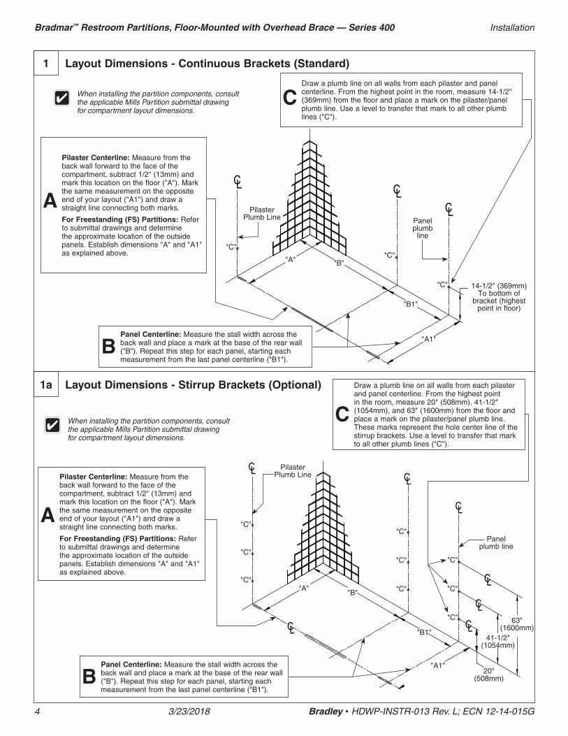
Top and Bottom Insert
Female (2)
Bottom Insert Male w/ Cutoff
Cam & Spacer (1)
Top Insert w/ Cam Male (1)
Aluminium Hinge Blank (4)
Left In and Right Out Assembly
Top Hinge Set
Bottom Hinge Set
Insert
Correct Incorrect
Hinge Blank
Aluminum Hinge Blank
Reference Mark
Reference Mark
Top and Bottom Insert
Female
Bottom Insert Male w/ Cutoff Cam & Spacer
Top Insert Male w/ Cam
Top Hinge Set
Bottom Hinge Set
Cam
Cutoff Cam
Right In and Left Out Assembly
9d Aluminum Wraparound Hinge (Optional)
Hinge blanks and inserts have reference marks that are used in setting the hinge position. The top hinge contains the cam and the bottom hinge has the cutoff cam with spacer.
Right-hand inswing (RHI)
Left-hand inswing (LHI)
Right-hand outswing (RHO)
Left-hand outswing
(LHO)
Pila
ster
Sid
eP
ilast
er S
ide
Pila
ster
Sid
eP
ilast
er S
ide
Doo
r S
ide
Doo
r S
ide
Doo
r S
ide
Doo
r S
ide
Before installing the hinges, make sure the door openings are the appropriate size, all pilasters are plumb and secured to the shoe, and that the headrail is installed.
Refer to your submittal drawings to determine each specific door swing for your application. The door swing is determined by facing the compartment from the outside. The image below can help determine the door swing type.
Separate the hinge components and ensure all parts are included as shown .A Find the hinge assembly that coincides with the door swing .
Arrange the hinge sets as shown .B
Align the reference marks of the inserts and hinge blanks as shown .C
Assemble inserts into the hinge blanks making sure the insert collar fits tightly against each of the hinge blanks .D

21
Installation Bradmar™ Restroom Partitions, Floor-Mounted with Overhead Brace — Series 400
Bradley • HDWP-INSTR-013 Rev. L; ECN 12-14-015G 3/23/2018
9d Aluminum Wraparound Hinge (Continued)
Determine and set the "at rest" position of the door by adjusting the position of the top male insert within the hinge blank (see detail below) .EOrientate the door so the heatsink is on the bottom . Position the upper hinge blank of the top hinge set so that it is 2" (51mm) from the top of the door . Using the hinge as a template, drill a Ø3/32" pilot hole, 1" (25mm) deep into the door edge . Secure the hinge to the door using the #8 x 1" screw provided .
Repeat for the lower hinge blank of the bottom hinge set, except the hinge should be positioned 2" (51mm) from the bottom of the door .
F
Using both hinges as a template, drill Ø1/4" holes through the door for all hinge holes . Secure the hinge to the door using the #10-24 x 3/4" barrel nuts and #10-24 x 3/4" shoulder screws provided .
G
Place the included cardboard spacer on the male insert of the bottom hinge set . Assemble and position on the door the missing halfs of both hinge sets . Use a piece of tape to hold the hinge sets together .
H
Place door on a 14" (356mm) spacer and slide into position . Make sure both hinge blanks slip around the pilaster and are tight against the pilaster edge .IUsing both hinges as a template, drill Ø1/4" holes through the pilaster for all hinge holes . Secure the hinge to the pilaster using the #10-24 x 3/4" barrel nuts and #10-24 x 3/4" shoulder screws provided .
J
Remove tape and cardboard spacer from the hinge sets .K
Make sure both hinge sets are fully engaged with each other. The cardboard spacer will set the needed knuckle gap for the cam to function properly.
Align Cammed Insert
Reference Mark
Align Cammed Insert
Reference Mark
Align Cammed Insert
Reference Mark
Closed 30° Open Positive Closed
Lower Hinge Blank Bottom Hinge Set
Upper Hinge Blank Bottom Hinge Set
Spacer 14" (356mm)
Lower Hinge Blank Top Hinge Set
Upper Hinge Blank Top Hinge Set

22
Bradmar™ Restroom Partitions, Floor-Mounted with Overhead Brace — Series 400 Installation
3/23/2018 Bradley • HDWP-INSTR-013 Rev. L; ECN 12-14-015G
10 Door Hardware for Inswing Doors - Stainless
Local codes vary from state to state. Check your local codes before installing the coat hook and door pulls.
3" (76mm)
3" (76mm)
Flat Strike/Keeper
Using the flat strike/keeper as a template, drill (2) Ø5/32" pilot holes, 3/4" (19mm) deep . Secure the flat strike/keeper to the pilaster using the #10 x 3/4" flat head screws provided .
F
5-1/2" (140mm)
With the door in the closed position, place flat strike/keeper so the latch slide bar fits within the top notch .
E
29-1/4" (743mm) (Bottom of Door)
43-1/4" (1099mm) A .F .F
Position latch centered top to bottom and with the leading edge 3/8" (10mm) from the door edge . Using the latch as a template, mark the hole locations and drill Ø7/32" pilot holes, 3/4" (19mm) deep . Secure latch to door with the #14 x 3/4" screws provided .
A
With the door in the closed position, place the strike/keeper on the pilaster and align the top so it is 1/4" (6mm) above the bottom of the latch slide bar . Using the strike/keeper as a template, mark the hole locations and drill Ø1/4" holes through the pilaster . Secure the strike/keeper to the pilaster with the #10-24 x 3/4" barrel nuts and #10-24 x 3/4" shoulder screws provided .
B
3/8" (10mm)
1/4" (6mm)
For 32" - 36" doors, mark the location for the top hole on the inside face of the door 29-1/4" (743mm) up from the bottom of 55" tall doors (43-1/4" [1099mm] above finished floor) and 5-1/2" (140mm) from the door edge . Drill (2) Ø1/4" holes (spaced 3-1/2" [89mm] apart) through the door and secure the door pulls to the door as shown with the #10-24 x 2" flat machine screws provided .C
Place the coat hook 3" (76mm) down from the top and 3" (76mm) from the latch side of the door (hook goes on the inside face of the door) . Using the hook as a template, drill (2) Ø5/32" pilot holes, 3/4" (19mm) deep . Secure with the #10 x 3/4" screws provided .
D
CL

23
Installation Bradmar™ Restroom Partitions, Floor-Mounted with Overhead Brace — Series 400
Bradley • HDWP-INSTR-013 Rev. L; ECN 12-14-015G 3/23/2018
10a Door Hardware for Inswing Doors - Aluminum
Local codes vary from state to state. Check your local codes before installing the coat hook and door pulls.
3" (76mm)
3" (76mm)
Flat Strike/Keeper
Flat Strike/Keeper: Using the flat strike/keeper as a template, drill (2) Ø5/32" pilot holes, 3/4" (19mm) deep . Secure the flat strike/keeper to the pilaster using the #10 x 3/4" flat head screws provided .
1-Ear Strike/Keeper: Using the 1-ear strike/keeper as a template, drill (3) Ø7/32" pilot holes, 3/4" (19mm) deep . Secure the 1-ear strike/keeper to the pilaster using the #14 x 3/4" screws provided .
F
5-1/2" (140mm)
With the door in the closed position, place flat strike/keeper on the pilaster and align the slot so it is centered around the latch slide bar .
E
29-1/4" (743mm) (Bottom of Door)
43-1/4" (1099mm) A .F .F
Position latch centered top to bottom and with the leading edge 3/8" (10mm) from the door edge . Using the latch as a template, mark the hole locations and drill Ø7/32" pilot holes, 3/4" (19mm) deep . Secure latch to door with the #14 x 3/4" screws provided .
A
With the door in the closed position, place the strike/keeper on the pilaster and align the slot so it is centered around the latch slide bar . Using the strike/keeper as a template, mark the hole locations and drill Ø1/4" holes through the pilaster . Secure the strike/keeper to the pilaster with the #10-24 x 3/4" barrel nuts and #10-24 x 3/4" shoulder screws provided .
B
3/8" (10 mm)
For 32" - 36" doors, mark the location for the top hole on the inside face of the door 29-1/4" (743mm) up from the bottom of 55" tall doors (43-1/4" [1099mm] above finished floor) and 5-1/2" (140mm) from the door edge . Drill (2) Ø1/4" holes (spaced 3-1/2" [89mm] apart) through the door and secure the door pulls to the door as shown with the #10-24 x 2" flat machine screws provided .C
Place coat hook 3" (76mm) down from the top and 3" (76mm) from the latch side of the door (hook goes on the inside face of the door) . Using the hook as a template, drill (2) Ø5/32" pilot holes, 3/4" (19mm) deep . Secure with the #10 x 3/4" screws provided .
D
CL
1-Ear Strike/Keeper
CL

24
Bradmar™ Restroom Partitions, Floor-Mounted with Overhead Brace — Series 400 Installation
3/23/2018 Bradley • HDWP-INSTR-013 Rev. L; ECN 12-14-015G
10b Door Hardware for No-Site Inswing Doors - Stainless
Local codes vary from state to state. Check your local codes before installing the coat hook and door pulls.
3" (76mm)
3" (76mm)
5-1/2" (140mm)
29-1/4" (743mm) (Bottom of Door)
43-1/4" (1099mm) A .F .F
Position latch centered top to bottom and with the leading edge 1-1/8" (29mm) from the "lip" of the door edge . Using the latch as a template, mark the hole locations and drill Ø7/32" pilot holes, 3/4" (19mm) deep . Secure latch to door with the #14 x 3/4" screws provided .A
With the door in the closed position, place the strike/keeper on the pilaster so the top edge is 1/4" (6mm) above the bottom of the latch slide bar and the leading edge is lined up with the edge of the pilaster notch (approximately 5/8" [16mm] from the side of the pilaster) . Using the strike/keeper as a template, mark the hole locations and drill Ø7/32 pilot holes, 3/4" (19mm) deep . Secure the strike/keeper to the pilaster with the #14 x 3/4" screws provided .
B
1-1/8" (29mm)
For 32" - 36" doors, mark the location for the top hole on the inside face of the door 29-1/4" (743mm) up from the bottom of 55" tall doors (43-1/4" [1099mm] above finished floor) and 5-1/2" (140mm) from the "lip" of the door edge . Drill (2) Ø1/4" holes (spaced 3-1/2" [89mm] apart) through the door and secure the door pulls to the door as shown with the #10-24 x 2" flat machine screws provided .
C
Place the coat hook 3" (76mm) down from the top and 3" (76mm) from the "lip" of the door edge (hook goes on the inside face of the door) . Using the hook as a template, drill (2) Ø5/32" pilot holes, 3/4" (19mm) deep . Secure with the #10 x 3/4" screws provided .
D
CL
1/4" (6mm)
Pilaster Notch Edge
Lip
25
Installation Bradmar™ Restroom Partitions, Floor-Mounted with Overhead Brace — Series 400
Bradley • HDWP-INSTR-013 Rev. L; ECN 12-14-015G 3/23/2018
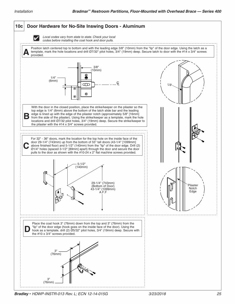
10c Door Hardware for No-Site Inswing Doors - Aluminum
Local codes vary from state to state. Check your local codes before installing the coat hook and door pulls.
3" (76mm)
3" (76mm)
5-1/2" (140mm)
29-1/4" (743mm) (Bottom of Door)
43-1/4" (1099mm) A .F .F
Position latch centered top to bottom and with the leading edge 3/8" (10mm) from the "lip" of the door edge . Using the latch as a template, mark the hole locations and drill Ø7/32" pilot holes, 3/4" (19mm) deep . Secure latch to door with the #14 x 3/4" screws provided .A
With the door in the closed position, place the strike/keeper on the pilaster so the top edge is 1/4" (6mm) above the bottom of the latch slide bar and the leading edge is lined up with the edge of the pilaster notch (approximately 5/8" [16mm] from the side of the pilaster) . Using the strike/keeper as a template, mark the hole locations and drill Ø7/32 pilot holes, 3/4" (19mm) deep . Secure the strike/keeper to the pilaster with the #14 x 3/4" screws provided .
B
3/8" (10mm)
For 32" - 36" doors, mark the location for the top hole on the inside face of the door 29-1/4" (743mm) up from the bottom of 55" tall doors (43-1/4" [1099mm] above finished floor) and 5-1/2" (140mm) from the "lip" of the door edge . Drill (2) Ø1/4" holes (spaced 3-1/2" [89mm] apart) through the door and secure the door pulls to the door as shown with the #10-24 x 2" flat machine screws provided .
C
Place the coat hook 3" (76mm) down from the top and 3" (76mm) from the "lip" of the door edge (hook goes on the inside face of the door) . Using the hook as a template, drill (2) Ø5/32" pilot holes, 3/4" (19mm) deep . Secure with the #10 x 3/4" screws provided .
D
CL
1/4" (6mm)
Pilaster Notch Edge
Lip

26
Bradmar™ Restroom Partitions, Floor-Mounted with Overhead Brace — Series 400 Installation
3/23/2018 Bradley • HDWP-INSTR-013 Rev. L; ECN 12-14-015G
10d Door Hardware for Outswing Doors - Stainless
Local codes vary from state to state. Check your local codes before installing the coat hook and door pulls.
3" (76mm)
3" (76mm)
Flat Strike/Keeper
Using the flat strike/keeper as a template, drill (2) Ø5/32" pilot holes, 3/4" (19mm) deep . Secure the flat strike/keeper to the pilaster using the #10 x 3/4" flat head screws provided .
G
5-1/2" (140mm)
With the door in the closed position, place the flat strike/keeper on the pilaster and align the top so it is 1/4" (6mm) above the bottom of the latch slide bar .
F
29-1/4" (743mm) (Bottom of Door)
43-1/4" (1099mm) A .F .F
Position latch centered top to bottom and with the leading edge 1" (25mm) from the door edge . Using the latch as a template, mark the hole locations and drill Ø7/32" pilot holes, 3/4" (19mm) deep . Secure latch to door with the #14 x 3/4" screws provided .A
With the door in the closed position, place the strike/keeper on the pilaster and align the top so it is 1/4" (6mm) above the bottom of the latch slide bar . Using the strike/keeper as a template, mark the hole locations and drill Ø1/4" holes through the pilaster . Secure the strike/keeper to the pilaster with the #10-24 x 3/4" barrel nuts and #10-24 x 3/4" shoulder screws provided .
B
1" (25mm)
1/4" (6mm)
Mark the location for the top hole on the inside face of the door 29-1/4" (743mm) up from the bottom of 55" tall doors (43-1/4" [1099mm] above finished floor) and 5-1/2" (140mm) from the door edge . Drill (2) Ø1/4" holes (spaced 3-1/2" [89mm] apart) through the door and secure the door pulls to the door as shown with the #10-24 x 2" flat machine screws provided .
C
Place wall bumper 3" (76mm) up from the bottom and 3" (76mm) from the latch side of the door (bumper goes on the outside face of the door) . Using the bumper as a template, drill (2) Ø5/32" pilot holes, 3/4" (19mm) deep . Secure with the #10 x 3/4" screws provided .
E
CL
36" (914mm)
A .F .F .
Position the coat hook 36" (914mm) above finished floor (hook goes on the inside of compartment) . Using the hook as a template, drill (2) Ø7/32" pilot holes, 3/4" (19mm) deep . Secure with the #14 x 3/4" screws provided .
D

27
Installation Bradmar™ Restroom Partitions, Floor-Mounted with Overhead Brace — Series 400
Bradley • HDWP-INSTR-013 Rev. L; ECN 12-14-015G 3/23/2018
10e Door Hardware for Outswing Doors - Aluminum
Local codes vary from state to state. Check your local codes before installing the coat hook and door pulls.
3" (76mm)
3" (76mm)
Flat Strike/Keeper: Using the flat strike/keeper as a template, drill (2) Ø5/32" pilot holes, 3/4" (19mm) deep . Secure the flat strike/keeper to the pilaster using the #10 x 3/4" flat head screws provided .
1-Ear Strike/Keeper: Using the 1-ear strike/keeper as a template, drill (3) Ø7/32" pilot holes, 3/4" (19mm) deep . Secure the 1-ear strike/keeper to the pilaster using the #14 x 3/4" screws provided .
G
5-1/2" (140mm)
With the door in the closed position, place flat strike/keeper so it is centered on the latch slide bar .
F
29-1/4" (743mm) (Bottom of Door)
43-1/4" (1099mm) A .F .F
Position latch centered top to bottom and with the leading edge 1" (25mm) from the door edge . Using the latch as a template, mark the hole locations and drill Ø7/32" pilot holes, 3/4" (19mm) deep . Secure latch to door with the #14 x 3/4" screws provided .A
With the door in the closed position, place the strike/keeper on the pilaster so it is centered on the latch slide bar . Using the strike/keeper as a template, mark the hole locations and drill Ø1/4" holes through the pilaster . Secure the strike/keeper to the pilaster with the #10-24 x 3/4" barrel nuts and #10-24 x 3/4" shoulder screws provided .
B
1" (25mm)
Mark the location for the top hole on the inside face of the door 29-1/4" (743mm) up from the bottom of 55" tall doors (43-1/4" [1099mm] above finished floor) and 5-1/2" (140mm) from the door edge . Drill (2) Ø1/4" holes (spaced 3-1/2" [89mm] apart) through the door and secure the door pulls to the door as shown with the #10-24 x 2" flat machine screws provided .
C
Place wall bumper 3" (76mm) up from the bottom and 3" (76mm) from the latch side of the door (bumper goes on the outside face of the door) . Using the bumper as a template, drill (2) Ø5/32" pilot holes, 3/4" (19mm) deep . Secure with the #10 x 3/4" screws provided .
E
CL
36" (914mm)
A .F .F .
Position the coat hook 36" (914mm) above finished floor (hook goes on the inside of compartment) . Using the hook as a template, drill (2) Ø7/32" pilot holes, 3/4" (19mm) deep . Secure with the #14 x 3/4" screws provided .
D
CL
Flat Strike/Keeper 1-Ear Strike/Keeper

28
Bradmar™ Restroom Partitions, Floor-Mounted with Overhead Brace — Series 400 Installation
3/23/2018 Bradley • HDWP-INSTR-013 Rev. L; ECN 12-14-015G
10f Door Hardware for No-Site Outswing Doors - Stainless
Local codes vary from state to state. Check your local codes before installing the coat hook and door pulls.
36" (914mm)
A .F .F .
5-1/2" (140mm)
29-1/4" (743mm) (Bottom of Door)
43-1/4" (1099mm) A .F .F
Position latch centered top to bottom and with the leading edge 1" (25mm) from the "inside face" door edge . Using the latch as a template, mark the hole locations and drill Ø7/32" pilot holes, 3/4" (19mm) deep . Secure latch to door with the #14 x 3/4" screws provided .A
With the door in the closed position, place the strike/keeper on the pilaster so the top edge is 1/4" (6mm) above the bottom of the latch slide bar and the leading edge is lined up with the edge of the pilaster notch (approximately 5/8" [16mm] from the side of the pilaster) . Using the strike/keeper as a template, mark the hole locations and drill Ø7/32 pilot holes, 3/4" (19mm) deep . Secure the strike/keeper to the pilaster with the #14 x 3/4" screws provided .
B
1" (25mm)
Mark the location for the top hole on the inside face of the door 29-1/4" (743mm) up from the bottom of 55" tall doors (43-1/4" [1099mm] above finished floor) and 5-1/2" (140mm) from the "lip" of the door edge . Drill (2) Ø1/4" holes (spaced 3-1/2" [89mm] apart) through the door and secure the door pulls to the door as shown with the #10-24 x 2" flat machine screws provided .
C
Position the coat hook 36" (914mm) above finished floor (hook goes on the inside of compartment) . Using the hook as a template, drill (2) Ø7/32" pilot holes, 3/4" (19mm) deep . Secure with the #14 x 3/4" screws provided .
D
CL
1/4" (6mm)
Pilaster Notch Edge
Lip
3" (76mm)
3" (76mm)
Place wall bumper 3" (76mm) up from the bottom and 3" (76mm) from the "lip" of the door edge (bumper goes on the outside face of the door) . Using the bumper as a template, drill (2) Ø5/32" pilot holes, 3/4" (19mm) deep . Secure with the #10 x 3/4" screws provided .
E
"Inside Face" Door Edge

29
Installation Bradmar™ Restroom Partitions, Floor-Mounted with Overhead Brace — Series 400
Bradley • HDWP-INSTR-013 Rev. L; ECN 12-14-015G 3/23/2018
10g Door Hardware for No-Site Outswing Doors - Aluminum
Local codes vary from state to state. Check your local codes before installing the coat hook and door pulls.
5-1/2" (140mm)
29-1/4" (743mm) (Bottom of Door)
43-1/4" (1099mm) A .F .F
Position latch centered top to bottom and with the leading edge 3/16" (5mm) from the "inside face" door edge . Using the latch as a template, mark the hole locations and drill Ø7/32" pilot holes, 3/4" (19mm) deep . Secure latch to door with the #14 x 3/4" screws provided .A
With the door in the closed position, place the strike/keeper on the pilaster so the top edge is 1/4" (6mm) above the bottom of the latch slide bar and the leading edge is lined up with the edge of the pilaster notch (approximately 5/8" [16mm] from the side of the pilaster) . Using the strike/keeper as a template, mark the hole locations and drill Ø7/32 pilot holes, 3/4" (19mm) deep . Secure the strike/keeper to the pilaster with the #14 x 3/4" screws provided .
B
3/16" (5mm)
Mark the location for the top hole on the inside face of the door 29-1/4" (743mm) up from the bottom of 55" tall doors (43-1/4" [1099mm] above finished floor) and 5-1/2" (140mm) from the "lip" of the door edge . Drill (2) Ø1/4" holes (spaced 3-1/2" [89mm] apart) through the door and secure the door pulls to the door as shown with the #10-24 x 2" flat machine screws provided .
C
CL
1/4" (6mm)
Pilaster Notch Edge
Lip
36" (914mm)
A .F .F .
Position the coat hook 36" (914mm) above finished floor (hook goes on the inside of compartment) . Using the hook as a template, drill (2) Ø7/32" pilot holes, 3/4" (19mm) deep . Secure with the #14 x 3/4" screws provided .
D
3" (76mm)
3" (76mm)
Place wall bumper 3" (76mm) up from the bottom and 3" (76mm) from the "lip" of the door edge (bumper goes on the outside face of the door) . Using the bumper as a template, drill (2) Ø5/32" pilot holes, 3/4" (19mm) deep . Secure with the #10 x 3/4" screws provided .
E
"Inside Face" Door Edge

30
Bradmar™ Restroom Partitions, Floor-Mounted with Overhead Brace — Series 400 Installation
3/23/2018 Bradley • HDWP-INSTR-013 Rev. L; ECN 12-14-015G
Stiffener at Door Hinge Stiffener at Door Strike
11 Stiffener Bracket
A stiffener bracket is required for all pilasters 16" and larger.
The stiffener bracket is installed on the largest side of a pilaster split.
Position stiffener bracket on pilaster so the bracket edge is 1/4" (6mm) from the integral hinge cutout and centered top to bottom .A
Using the bracket as a template, drill Ø7/32" pilot holes, 3/4" (19mm) deep . Secure the bracket to the pilaster with the #14 x 5/8" screws provided .B
For wraparound and continuous hinges, position 1/4" (6mm) from the hinge edge.
Position stiffener bracket on pilaster so the bracket edge is 1/4" (6mm) from the strike/keeper and centered top to bottom .AUsing the bracket as a template, drill Ø7/32" pilot holes, 3/4" (19mm) deep . Secure the bracket to the pilaster with the #14 x 5/8" screws provided .B
1/4" (6mm)
1/4" (6mm)
1/4" (6mm)
1/4" (6mm)

31
Installation Bradmar™ Restroom Partitions, Floor-Mounted with Overhead Brace — Series 400
Bradley • HDWP-INSTR-013 Rev. L; ECN 12-14-015G 3/23/2018
Before installing the urinal screen components, determine the correct location for your application.
Draw a plumb line on the wall to represent the urinal screen centerline . Measure from the highest point in the room and place a mark on the urinal screen centerline at dimension "A" for the respective urinal screen height (see table below) .
A
Insert plastic anchors in all holes and secure bracket to the wall with the #14 x 2" screws provided .C
Place the bottom of the bracket on the mark and center the opening on the urinal screen centerline . Using the bracket as a template, mark the hole locations on the wall . Remove the bracket and drill a Ø5/16" hole (minimum 2" [51mm] deep) at each hole location .
B
12 Urinal Screens with Continuous Stainless Steel Brackets (Standard)
Using the bracket as a template, drill Ø1/4" holes through the urinal screen at each bracket hole . Secure the urinal screen to the bracket with the #10-24 x 3/4" barrel nuts and #10-24 x 3/4" shoulder screws provided .
E
Place the urinal screen at dimension "B" for the respective urinal screen height (see table on right) and insert it into the wall bracket until a 1" (25mm) gap between the wall and urinal screen is established .
D
"A"
floor "B"
Urinal Plumb Line
Dim "A" Dim "B"
42" Urinal Screen 18-1/2" (470mm) 18" (457mm)
48" Urinal Screen 12-1/2" (318mm) 12" (305mm)
Brackets are used as templates, but since the hole patterns may be different, the brackets may not be interchangeable.

32
Bradmar™ Restroom Partitions, Floor-Mounted with Overhead Brace — Series 400 Installation
3/23/2018 Bradley • HDWP-INSTR-013 Rev. L; ECN 12-14-015G
Before installing the urinal screen components, determine the correct location for your application.
Draw a plumb line on the wall to represent the urinal screen centerline . Measure from the highest point in the room and place a mark on the urinal screen centerline at dimension "A" for the respective urinal screen height (see table below) .
A
Insert plastic anchors in all holes and secure bracket to the wall with the #14 x 2" screws provided .C
Place the bottom of the bracket on the mark and center the opening on the urinal screen centerline . Using the bracket as a template, mark the hole locations on the wall . Remove the bracket and drill a Ø5/16" hole (minimum 2" [51mm] deep) at each hole location .
B
12a Urinal Screens with Continuous Aluminum Brackets (Optional)
Using the bracket as a template, drill Ø1/4" holes through the urinal screen at each bracket hole . Secure the urinal screen to the bracket with the #10-24 x 3/4" barrel nuts and #10-24 x 3/4" shoulder screws provided .
E
Place the urinal screen at dimension "B" for the respective urinal screen height (see table on right) and insert it into the wall bracket until a 1" (25mm) gap between the wall and urinal screen is established .
D
"A"
floor "B"
Urinal Plumb Line
Brackets are used as templates, but since the hole patterns may be different, the brackets may not be interchangeable.
Dim "A" Dim "B"
42" Urinal Screen 18-1/4" (464mm) 18" (457mm)
48" Urinal Screen 15-1/4" (387mm) 12" (305mm)

33
Installation Bradmar™ Restroom Partitions, Floor-Mounted with Overhead Brace — Series 400
Bradley • HDWP-INSTR-013 Rev. L; ECN 12-14-015G 3/23/2018
12b Urinal Screens with Stirrup Brackets (Optional)
Before installing the urinal screen components, determine the correct location for your application.
Draw a plumb line on the wall to represent the urinal screen centerline . Measure from the highest point in the room and place a mark on the urinal screen centerline at dimensions "A", "B" and "C" for the respective urinal screen height (see table below) .
A
Position and center brackets at each mark and urinal screen centerline . Using the bracket as a temp late, mark the hole locations on the wall . Remove the bracket and drill a Ø5/16" hole (minimum 2" [51mm] deep) at each hole location .
B
Place the urinal screen at dimension "D" for the respective urinal screen height (see table on right) and insert it into the wall brackets until a 1" (25mm) gap between the wall and urinal screen is established .
D
Insert plastic anchors in all holes and secure bracket to the wall with the #14 x 2" screws provided .C
Using the bracket as a template, drill Ø1/4" holes through the urinal screen at each bracket hole . Secure the urinal screen to the brackets with the #10-24 x 3/4" barrel nuts and #10-24 x 3/4" shoulder screws provided .
E
"A"
"B"
floor
Dim "A" Dim "B" Dim "C" Dim "D"
42" Urinal Screen 24" (610mm) 39" (991mm) 54" (1372mm) 18" (457mm)
48" Urinal Screen 18" (457mm) 36" (914mm) 54" (1372mm) 12" (305mm)
"C"
Urinal Plumb Line
"D"