Installation - Bradley Corp · LD-5010 alla 2 8/24/2017 Bradley • 215-1869 Rev. B; ECN 17-11-004B...
28
Installation P.O. Box 309 Menomonee Falls, WI 53052 USA 800 BRADLEY (800 272 3539) +1 262 251 6000 bradleycorp.com 215-1869 Rev. B; ECN 17-11-004B © 2017 Bradley Page 1 of 28 8/24/2017 LD-5010 OmniDeck ™ with WashBar ™ - 5000 Series Table of Contents Pre-Installation Information................................................ 2 Supplies Required ............................................................. 2 Components ................................................................... 3-4 Dimensions ................................................................... 5-10 Structural Rough-Ins........................................................ 11 Plumbing and Electrical Rough-Ins ................................. 12 Drain Assembly ............................................................... 13 WashBar Installation ........................................................ 13 Aerator Installation........................................................... 14 Attach Soap Motor and Soap Container Bracket ............ 14 Bowl Mounting ................................................................. 15 Install P-Trap.................................................................... 15 Strainer and Drain Cap.................................................... 15 Dryer Motor Assembly ..................................................... 16 Attach Power Line Filter .................................................. 17 Control Box and Valve Installation ................................... 18 Soap Installation .............................................................. 19 Electrical Connections ..................................................... 20 Adjust Temperature with Water Running ......................... 20 Access Panel ................................................................... 21 Master Control Box ..................................................... 22-26 Cleaning and Maintenance......................................... 27-28
Transcript of Installation - Bradley Corp · LD-5010 alla 2 8/24/2017 Bradley • 215-1869 Rev. B; ECN 17-11-004B...

Installation
P.O. Box 309Menomonee Falls, WI 53052 USA
800 BRADLEY (800 272 3539)+1 262 251 6000bradleycorp.com
215-1869 Rev. B; ECN 17-11-004B© 2017 BradleyPage 1 of 28 8/24/2017
LD-5010OmniDeck™ with WashBar™ - 5000 Series
Table of ContentsPre-Installation Information ................................................2Supplies Required .............................................................2Components ...................................................................3-4Dimensions ...................................................................5-10Structural Rough-Ins ........................................................11Plumbing and Electrical Rough-Ins .................................12Drain Assembly ...............................................................13WashBar Installation ........................................................13Aerator Installation ...........................................................14Attach Soap Motor and Soap Container Bracket ............14Bowl Mounting .................................................................15Install P-Trap ....................................................................15Strainer and Drain Cap ....................................................15Dryer Motor Assembly .....................................................16Attach Power Line Filter ..................................................17Control Box and Valve Installation ...................................18Soap Installation ..............................................................19Electrical Connections .....................................................20Adjust Temperature with Water Running .........................20Access Panel ...................................................................21Master Control Box .....................................................22-26Cleaning and Maintenance .........................................27-28
LD-5010 Installation
2 8/24/2017 Bradley • 215-1869 Rev. B; ECN 17-11-004B
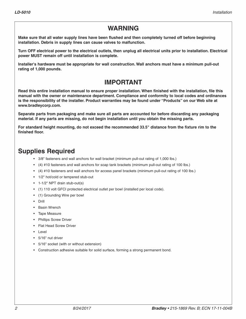
WARNINGMake sure that all water supply lines have been flushed and then completely turned off before beginning installation. Debris in supply lines can cause valves to malfunction.
Turn OFF electrical power to the electrical outlets, then unplug all electrical units prior to installation. Electrical power MUST remain off until installation is complete.
Installer's hardware must be appropriate for wall construction. Wall anchors must have a minimum pull-out rating of 1,000 pounds.
IMPORTANTRead this entire installation manual to ensure proper installation. When finished with the installation, file this manual with the owner or maintenance department. Compliance and conformity to local codes and ordinances is the responsibility of the installer. Product warranties may be found under “Products” on our Web site at www.bradleycorp.com.
Separate parts from packaging and make sure all parts are accounted for before discarding any packaging material. If any parts are missing, do not begin installation until you obtain the missing parts.
For standard height mounting, do not exceed the recommended 33.5" distance from the fixture rim to the finished floor.
Supplies Required• 3/8" fasteners and wall anchors for wall bracket (minimum pull-out rating of 1,000 lbs.)
• (4) #10 fasteners and wall anchors for soap tank brackets (minimum pull-out rating of 100 lbs.)
• (4) #10 fasteners and wall anchors for access panel brackets (minimum pull-out rating of 100 lbs.)
• 1/2" hot/cold or tempered stub-out
• 1-1/2" NPT drain stub-out(s)
• (1) 110 volt GFCI protected electrical outlet per bowl (installed per local code).
• (1) Grounding Wire per bowl
• Drill
• Basin Wrench
• Tape Measure
• Phillips Screw Driver
• Flat Head Screw Driver
• Level
• 5/16" nut driver
• 5/16" socket (with or without extension)
• Construction adhesive suitable for solid surface, forming a strong permanent bond.
Installation LD-5010
Bradley • 215-1869 Rev. B; ECN 17-11-004B 8/24/2017 3
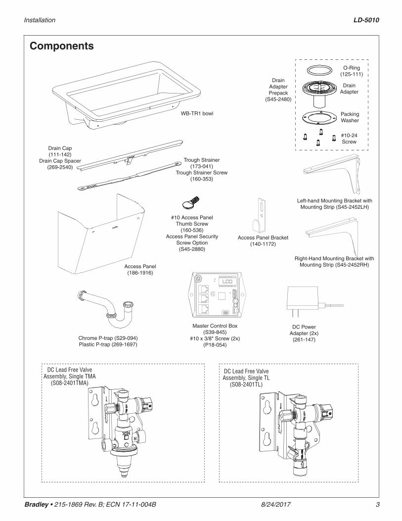
Components
WB-TR1 bowl
Chrome P-trap (S29-094)Plastic P-trap (269-1697)
Access Panel (186-1916)
DC Power Adapter (2x)
(261-147)
Drain Cap (111-142)
Drain Cap Spacer (269-2540)
Trough Strainer (173-041)
Trough Strainer Screw(160-353)
O-Ring (125-111)
Drain Adapter
Packing Washer
#10-24 Screw
Drain Adapter Prepack
(S45-2480)
Master Control Box (S39-845)
#10 x 3/8" Screw (2x) (P18-054)
Access Panel Bracket (140-1172)
#10 Access Panel Thumb Screw
(160-536)Access Panel Security
Screw Option (S45-2880)
Right-Hand Mounting Bracket with Mounting Strip (S45-2452RH)
Left-hand Mounting Bracket with Mounting Strip (S45-2452LH)
DC Lead Free Valve Assembly, Single TMA
(S08-2401TMA)
DC Lead Free Valve Assembly, Single TL
(S08-2401TL)

LD-5010 Installation
4 8/24/2017 Bradley • 215-1869 Rev. B; ECN 17-11-004B
Components
Control Box Assembly with Liquid Pump (S52-166)
Control Box Assembly with Foam Pump (S52-167)
Gallon Jug (Supplied by Others)
Soap Tank Bracket (140-1171)
Hose Clamps - 2-1/2" Dia (269-678)
Flexible PVC (269-2561A)
Dryer Motor (S39-844)
Dryer Vibration Pad 4" x 10"
(124-105) (Not Shown)
Hook and Loop Strap (269-2574)
Hook and Loop Strap (not shown) (269-2574)
Liquid Pump with External Rubber Sleeve Connection
(269-2518) Foam Pump with Internal
Press Fit Connection (269-2519)
Casting ASM. WashBar, Chrome w/ LED (S05-214F01)
Union Tube, 1/4" OD (269-624)
1/4" x 60 Tubing (269-547C) For Service - 1' Increments (R68-600011)
Elbow, 1/4 x 3.4mm Hose Barb (145-221)
Gasket WashBar Deck, Soap Side
(124-101)
Soap Tube 5.5mm OD x 55cm long
(269-2522)
Access Plate ASM, Soap with Sensor
Printed Circuit Board (S04-121)
Aerator .50 GPM (S05-175) Aerator .35 GPM (S05-215) (Aerators are shipped loose in bag with red service key)
Nut, WashBar, 1-3/8-18 (110-256)
Washer Ground .25" QC (230-035)
Gasket, WashBar Deck, Air Side (124-102)
Screw #4-40 x 1/2 Pan Mach SS (160-418)
Screw, #4-40 x 1/4 Pan Mach SS Black Oxide
(160-534)
Access Plate ASM, Air/Water with Sensor Printed Cricuit Board
(S04-122)
Union Elbow (269-2531)
Nut, WashBar, 1-3/8-18
(110-256)

Installation LD-5010
Bradley • 215-1869 Rev. B; ECN 17-11-004B 8/24/2017 5
Dimensions - 1-Person
Top View
Front View
(mm)
30" (762)
20-1/2" (521)
5" (127)
11-1/2" (292)
13-1/2" (343)
3-1/8" (79)
11" (279)
10-3/4" (273)
5" (127)
19-1/8" (485)
22-1/2" (571)
5" (127)
21-5/8" (549)

LD-5010 Installation
6 8/24/2017 Bradley • 215-1869 Rev. B; ECN 17-11-004B
Dimensions - 2-Person
Top View
Front View
(mm)
60" (1524)
20-1/2" (521)
11-1/2" (292)
10-3/4" (273)
5" (127)
13-1/2" (343)
3-1/8" (79)
11" (279)
19-1/5" (485)
5" (127)
5" (127)
22-1/2" (571)
21-5/8" (549)
Installation LD-5010
Bradley • 215-1869 Rev. B; ECN 17-11-004B 8/24/2017 7
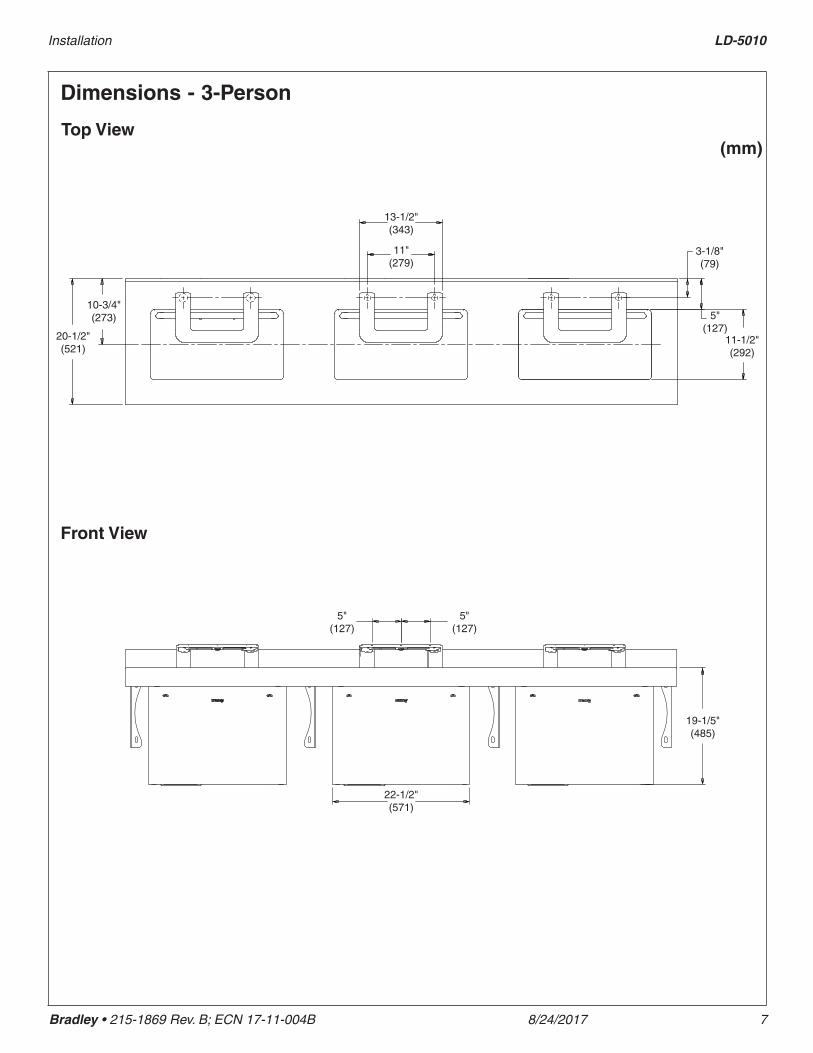
Dimensions - 3-Person
Top View
Front View
(mm)
20-1/2" (521)
11-1/2" (292)
10-3/4" (273) 5"
(127)
13-1/2" (343)
3-1/8" (79)
19-1/5" (485)
5" (127)
5" (127)
22-1/2" (571)
11" (279)

LD-5010 Installation
8 8/24/2017 Bradley • 215-1869 Rev. B; ECN 17-11-004B
Dimensions - 4-Person
Top View
Front View
(mm)
20-1/2" (521)
11-1/2" (292)
10-3/4" (273) 5"
(127)
13-1/2" (343)
3-1/8" (79)
19-1/5" (485)
5" (127)
5" (127)
22-1/2" (571)
11" (279)
21-5/8" (549)
Installation LD-5010
Bradley • 215-1869 Rev. B; ECN 17-11-004B 8/24/2017 9
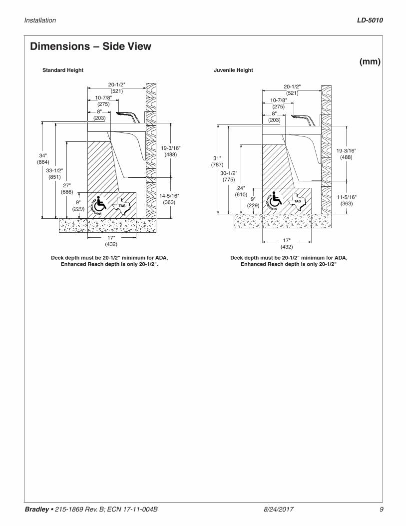
Dimensions – Side View(mm)
Standard Height Juvenile Height
Deck depth must be 20-1/2" minimum for ADA, Enhanced Reach depth is only 20-1/2".
Deck depth must be 20-1/2" minimum for ADA, Enhanced Reach depth is only 20-1/2"
20-1/2" (521)
8" (203)
34" (864)
33-1/2" (851)
27" (686)
9" (229)
17" (432)
14-5/16" (363)
19-3/16" (488)
10-7/8" (275)
20-1/2" (521)
8" (203)
31" (787)
30-1/2" (775)
9" (229)
17" (432)
11-5/16" (363)
19-3/16" (488)
24" (610)
10-7/8" (275)
LD-5010 Installation
10 8/24/2017 Bradley • 215-1869 Rev. B; ECN 17-11-004B
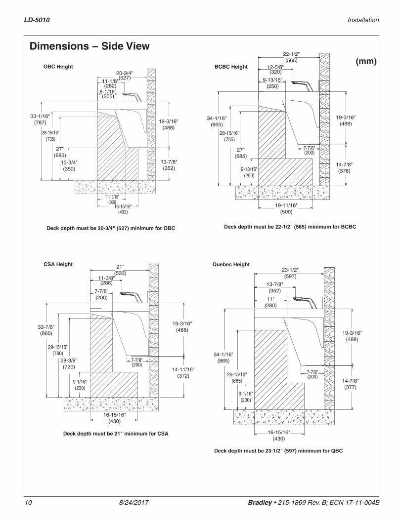
OBC Height BCBC Height
CSA Height Quebec Height
Deck depth must be 20-3/4" (527) minimum for OBC Deck depth must be 22-1/2" (565) minimum for BCBC
Deck depth must be 21" minimum for CSA
Deck depth must be 23-1/2" (597) minimum for QBC
Dimensions – Side View(mm)
20-3/4" (527)
8-1/16" (205)
33-1/16" (787)
28-15/16" (735)
13-3/4" (350)
16-15/16" (432)
13-7/8" (352)
19-3/16" (488)
27" (685)
11-13/16" (300)
11-1/8" (282)
22-1/2" (565)
9-13/16" (250)
34-1/16" (865)
28-15/16" (735)
27" (685)
9-13/16" (250)
19-11/16" (500)
14-7/8" (378)
19-3/16" (488)
7-7/8" (200)
12-5/8" (320)
21" (533)
7-7/8" (200)
33-7/8" (860)
29-15/16" (760)
28-3/8" (720)
9-1/16" (230)
16-15/16" (430)
14-11/16" (372)
19-3/16" (488)
7-7/8" (200)
11-3/8" (288)
23-1/2" (597)
11" (280)
34-1/16" (865)
26-15/16" (685)
9-1/16" (230)
16-15/16" (430)
14-7/8" (377)
19-3/16" (488)
7-7/8" (200)
13-7/8" (352)

Installation LD-5010
Bradley • 215-1869 Rev. B; ECN 17-11-004B 8/24/2017 11
Structural Rough-Ins (mm)
CODE DESCRIPTION QTY.A 3/8" wall anchors with a minimum pull-out force of 1,000 lbs. per local codes 2 per bracket
C Install wall anchor with a minimum pull-out force of 100 lbs. per local codes at locations shown 4
S #10 Wall Anchors for Soap Control Box Bracket 4
S1 #10 Wall Anchors for Soap Tank Bracket (100 lb pull out force) 4
13-1/4" min (337)
13-1/4" min (337)
9" (229)
33-1/2" (851)
Deck Height
21-3/4" (552)
15-5/8" (396)
3/4" (19)
15-9/16" (394)
10-3/8" (264)
3-1/4" (83)
5-1/2" (140)
13" (330)
10-3/8" (264)
5" (127)
3-1/2" (89)
A
A
S S
C
CS1S1
A
A
C
C
CLTypical OmniDeck rough-ins for single WB-TR1 bowl are shown. Other multiple-bowl rough-ins are similar.
Finished Floor
RIM HEIGHT VERTICAL HEIGHT ADJUSTMENTS FIXTURE STYLE34" No Adjustment Standard Height, ADA, TAS
31 Subtract 3" Juvenile, ADA and TAS
33-1/16" Subtract 15/16" OBC
34-1/16" Add 1/16" BCBC and QBC
33-7/8" Subtract 1/8" CSA

LD-5010 Installation
12 8/24/2017 Bradley • 215-1869 Rev. B; ECN 17-11-004B
Plumbing and Electrical Rough-Ins
Mounting for Standard, ADA and TAS height shown.(mm)
CODE DESCRIPTION QTY.A 1½" NPT Drain, Stub-out 2" from wall 1
H,C ½" Nominal (⁵⁄₈" O.D. Comp.) Hot/Cold supplies, Stub-out 2" from wall 1
E 110V GFI protected electrical outlet (15 amp circuit breaker) 1
CL
9" (229)
33-1/2" (851)
Deck Height
23-3/4" (603)
E
17-1/2" (444)
2-1/4" (57)
1" (25)
H C
23-3/4" (603)
W
1" (25)
Finished Floor
Typical OmniDeck rough-ins for single WB-TR1 bowl are shown. Other multiple-bowl rough-ins are similar.
Tempered Supply
Installation LD-5010
Bradley • 215-1869 Rev. B; ECN 17-11-004B 8/24/2017 13
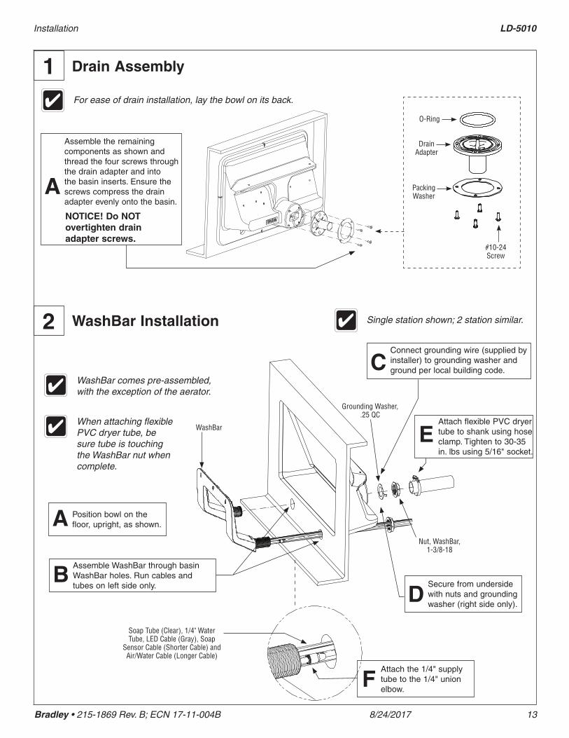
For ease of drain installation, lay the bowl on its back.
1 Drain Assembly
O-Ring
Drain Adapter
Packing Washer
#10-24 Screw
Assemble the remaining components as shown and thread the four screws through the drain adapter and into the basin inserts. Ensure the screws compress the drain adapter evenly onto the basin.
A
WashBar Installation2 Single station shown; 2 station similar.
Assemble WashBar through basin WashBar holes. Run cables and tubes on left side only.
B Secure from underside with nuts and grounding washer (right side only).
D
WashBar
Grounding Washer, .25 QC
Nut, WashBar, 1-3/8-18
Connect grounding wire (supplied by installer) to grounding washer and ground per local building code. C
Position bowl on the floor, upright, as shown.A
Soap Tube (Clear), 1/4" Water Tube, LED Cable (Gray), Soap
Sensor Cable (Shorter Cable) and Air/Water Cable (Longer Cable)
WashBar comes pre-assembled, with the exception of the aerator.
Attach flexible PVC dryer tube to shank using hose clamp. Tighten to 30-35 in. lbs using 5/16" socket.
E
Attach the 1/4" supply tube to the 1/4" union elbow.
F
When attaching flexible PVC dryer tube, be sure tube is touching the WashBar nut when complete.
NOTICE! Do NOT overtighten drain adapter screws.
LD-5010 Installation
14 8/24/2017 Bradley • 215-1869 Rev. B; ECN 17-11-004B
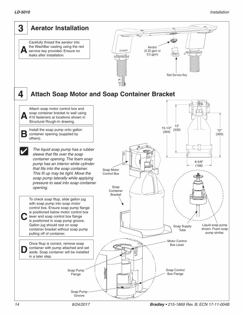
Aerator Installation3
Red Service Key
Aerator (0.35 gpm or
0.5 gpm)
Carefully thread the aerator into the WashBar casting using the red service key provided. Ensure no leaks after installation.
A
Attach Soap Motor and Soap Container Bracket4Attach soap motor control box and soap container bracket to wall using #10 fasteners at locations shown in Structural Rough-In drawing.
AInstall the soap pump onto gallon container opening (supplied by others).
BThe liquid soap pump has a rubber sleeve that fits over the soap container opening. The foam soap pump has an interior white cylinder that fits into the soap container. This fit up may be tight. Move the soap pump laterally while applying pressure to seat into soap container opening.
Soap Motor Control Box
Soap Container Bracket
To check soap fitup, slide gallon jug with soap pump into soap motor control box. Ensure soap pump flange is positioned below motor control box lever and soap control box flange is positioned in soap pump groove. Gallon jug should rest on soap container bracket without soap pump pulling off of container.
C
Soap Pump Flange
Motor Control Box LeverOnce fitup is correct, remove soap
container with pump attached and set aside. Soap container will be installed in a later step.
D
Soap Control Box Flange
Soap Pump Groove
15-1/2"(394)
13"(330)
6-5/8"(168)
12"(305)
Liquid soap pump shown. Foam soap
pump similar.
Soap Supply Tube
Installation LD-5010
Bradley • 215-1869 Rev. B; ECN 17-11-004B 8/24/2017 15
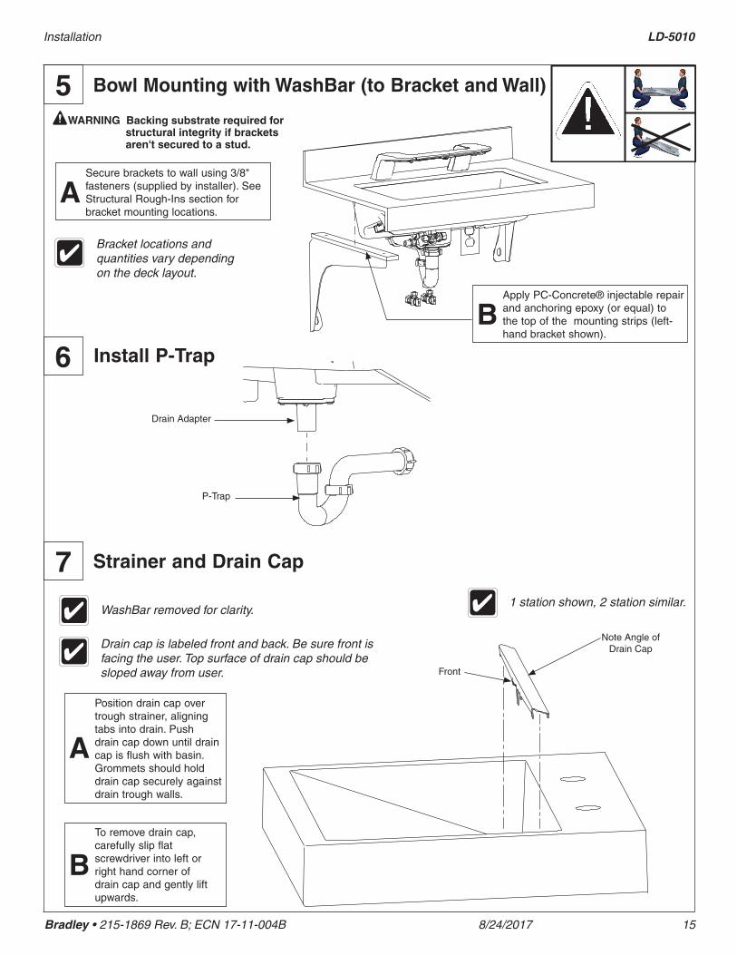
Bowl Mounting with WashBar (to Bracket and Wall)5
Apply PC-Concrete® injectable repair and anchoring epoxy (or equal) to the top of the mounting strips (left-hand bracket shown).
B
WARNING Backing substrate required for structural integrity if brackets aren't secured to a stud.
1 station shown, 2 station similar.
Strainer and Drain Cap7
Position drain cap over trough strainer, aligning tabs into drain. Push drain cap down until drain cap is flush with basin. Grommets should hold drain cap securely against drain trough walls.
A
To remove drain cap, carefully slip flat screwdriver into left or right hand corner of drain cap and gently lift upwards.
B
WashBar removed for clarity.
Front
Note Angle of Drain CapDrain cap is labeled front and back. Be sure front is
facing the user. Top surface of drain cap should be sloped away from user.
Install P-Trap6
Drain Adapter
P-Trap
Secure brackets to wall using 3/8" fasteners (supplied by installer). See Structural Rough-Ins section for bracket mounting locations.
A
Bracket locations and quantities vary depending on the deck layout.
LD-5010 Installation
16 8/24/2017 Bradley • 215-1869 Rev. B; ECN 17-11-004B
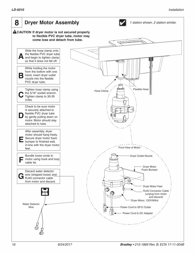
Dryer Motor Assembly8
Slide the hose clamp onto the flexible PVC dryer tube and begin to tighten clamp so that it does not fall off.
A
Dryer Outlet Nozzle
Dryer Motor Foam Bumper
Dryer Motor Feet
Power Cord to GFCI Outlet
Dryer Motor, 120V/60Hz
Power Cord to DC Adapter
After assembly, dryer motor should hang freely. Secure dryer motor foam bumper to finished wall, in-line with the dryer motor feet.
E
Discard water detector wire (shipped loose) and RJ45 connector cable from motor and discard.
G
Bundle loose cords to motor using hook and loop cable tie.F
Flexible HoseHose Clamp
Front View of Motor
CAUTION If dryer motor is not secured properly to flexible PVC dryer tube, motor may come lose and detach from tube.
While holding the motor from the bottom with one hand, insert dryer outlet nozzle into the flexible PVC dryer tube.
B
Tighten hose clamp using the 5/16" socket wrench. Tighten clamp to 30-35 in/lbs.
CCheck to be sure motor is securely attached to flexible PVC dryer tube by gently pulling down on motor. Motor should stay attached to tube.
D
RJ45 Connector Cable (unplug from motor
and discard)
1 station shown, 2 station similar.
Water Detector Wire
Installation LD-5010
Bradley • 215-1869 Rev. B; ECN 17-11-004B 8/24/2017 17
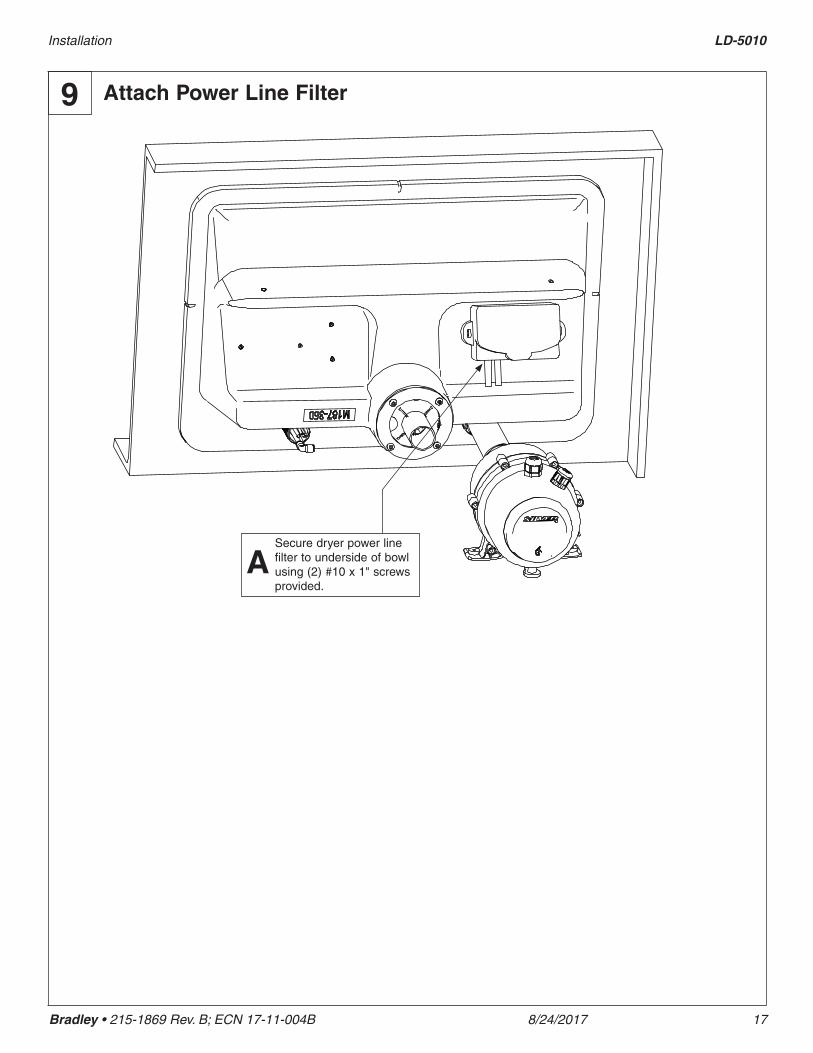
Attach Power Line Filter9
Secure dryer power line filter to underside of bowl using (2) #10 x 1" screws provided.
A
LD-5010 Installation
18 8/24/2017 Bradley • 215-1869 Rev. B; ECN 17-11-004B
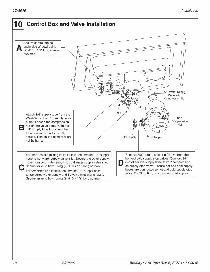
Control Box and Valve Installation10
Secure control box to underside of bowl using (2) #10 x 1/2" long screws provided.
A
1/4" Water Supply Outlet with
Compression Nut
Cold SupplyHot Supply
Cold
Hot
Attach 1/4" supply tube from the WashBar to the 1/4" supply valve outlet. Loosen the compression nut on the valve body. Push the 1/4" supply tube firmly into the tube connector until it is fully seated. Tighten the compression nut by hand.
B
For thermostatic mixing valve installation, secure 1/2" supply hose to hot water supply valve inlet. Secure the other supply hose from cold water supply to cold water supply valve inlet. Secure valve to bowl using (2) #10 x 1/2" long screws.
For tempered line installation, secure 1/2" supply hose to tempered water supply and TL valve inlet (not shown). Secure valve to bowl using (2) #10 x 1/2" long screws.
C
3/8" Compression
Nut
Remove 3/8" compression nut/sleeve from the hot and cold supply stop valves. Connect 3/8" end of flexible supply hose to 3/8" compression on supply stop valve. Ensure hot and cold supply hoses are connected to hot and cold supply stop valve. For TL option, only connect cold supply.
D
Installation LD-5010
Bradley • 215-1869 Rev. B; ECN 17-11-004B 8/24/2017 19
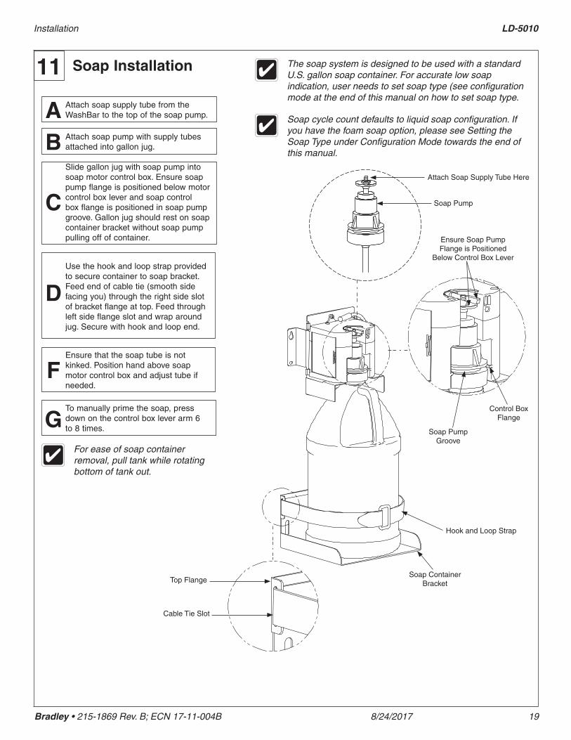
Soap Installation11 The soap system is designed to be used with a standard U.S. gallon soap container. For accurate low soap indication, user needs to set soap type (see configuration mode at the end of this manual on how to set soap type.
Attach soap supply tube from the WashBar to the top of the soap pump.A
To manually prime the soap, press down on the control box lever arm 6 to 8 times.G
Use the hook and loop strap provided to secure container to soap bracket. Feed end of cable tie (smooth side facing you) through the right side slot of bracket flange at top. Feed through left side flange slot and wrap around jug. Secure with hook and loop end.
D
Ensure that the soap tube is not kinked. Position hand above soap motor control box and adjust tube if needed.
F
Slide gallon jug with soap pump into soap motor control box. Ensure soap pump flange is positioned below motor control box lever and soap control box flange is positioned in soap pump groove. Gallon jug should rest on soap container bracket without soap pump pulling off of container.
C
Attach soap pump with supply tubes attached into gallon jug.B
For ease of soap container removal, pull tank while rotating bottom of tank out.
Ensure Soap Pump Flange is Positioned
Below Control Box Lever
Attach Soap Supply Tube Here
Top Flange
Cable Tie Slot
Soap Container Bracket
Hook and Loop Strap
Soap Pump
Soap cycle count defaults to liquid soap configuration. If you have the foam soap option, please see Setting the Soap Type under Configuration Mode towards the end of this manual.
Control Box Flange
Soap Pump Groove
LD-5010 Installation
20 8/24/2017 Bradley • 215-1869 Rev. B; ECN 17-11-004B
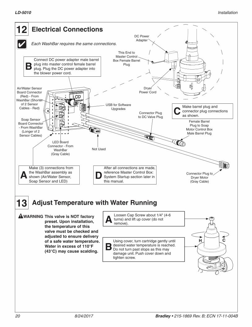
Electrical Connections12
Air/Water Sensor Board Connector
(Red) - From WashBar (Shorter
of 2 Sensor Cables - Red)
Soap Sensor Board Connector - From WashBar
(Longer of 2 Sensor Cables)
LED Board Connector - From
WashBar (Gray Cable)
Not Used
Connector Plug to DC Valve Plug
Female Barrel Plug to Soap
Motor Control Box Male Barrel Plug
Connector Plug to Dryer Motor (Gray Cable)
Make (3) connections from the WashBar assembly as shown (Air/Water Sensor, Soap Sensor and LED)
A
Make barrel plug and connector plug connections as shown.
CUSB for Software
Upgrades
Each WashBar requires the same connections.
After all connections are made, reference Master Control Box: System Startup section later in this manual.
D
Adjust Temperature with Water Running
H C
ALoosen Cap Screw about 1/4" (4-6 turns) and lift up cover (do not remove).
BUsing cover, turn cartridge gently until desired water temperature is reached. Do not turn past stops as this may damage unit. Push cover down and tighten screw.
WARNING This valve is NOT factory preset. Upon installation, the temperature of this valve must be checked and adjusted to ensure delivery of a safe water temperature. Water in excess of 110°F (43°C) may cause scalding.
13
Connect DC power adapter male barrel plug into master control female barrel plug. Plug the DC power adapter into the blower power cord.
B
This End to Master Control
Box Female Barrel Plug
DC Power Adapter
Dryer Power Cord

Installation LD-5010
Bradley • 215-1869 Rev. B; ECN 17-11-004B 8/24/2017 21
Install access panel brackets to wall using #10 fasteners (supplied by installer) as shown in rough in drawing. Install top screw into slot. Do not install bottom screw until Step C is complete.
A
Make all connections before installing access panel.
Access Panel14
#10 Top Screw
Shown in closed position. Rotate
90° to Open
Insert #10 thumbscrews into front bowl apron as shown. Thumbscrew in vertical position is closed. Thumbscrew in horizontal position is open.
B
Hang access panel onto mounting brackets attached to wall on the left and right sides. Rotate panel up and check fitup between thumbscrews and panel slots. Rotate access panel down and make adjustment to brackets if necessary. Install bottom #10 fastener into brackets.
C
Rotate access panel up and secure by rotating thumbscrews to the closed position
DTo open access panel, rotate thumb screw, slightly push panel up and swing access panel down. Do not remove thumbscrews.
E
#10 Thumb Screw
CAUTION For applications where children are present or for applications subject to vandalism, order security screw option S45-2880.
Attach P-trap to drain adapter and waste outlet.DPlug dryer power cord from dryer motor into GFCI protected wall outlet. WashBar LED's will light up blue. Wait 5 seconds. Place hands under soap dispenser, water and dryer to be sure all 3 functions work properly. Check for water leaks.
EInformation
label
LD-5010 Installation
22 8/24/2017 Bradley • 215-1869 Rev. B; ECN 17-11-004B
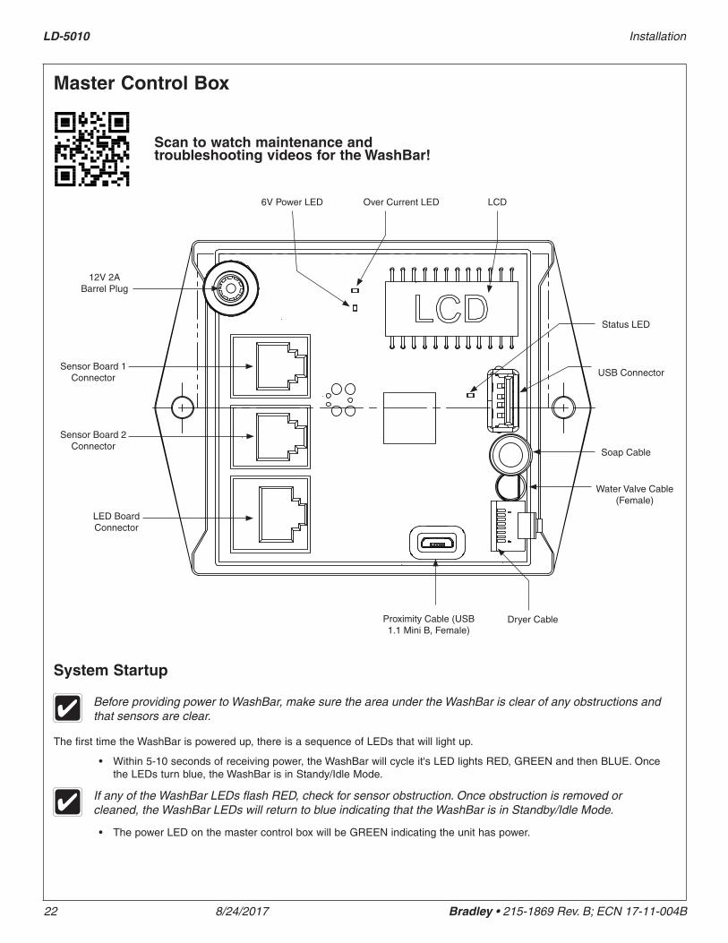
Master Control Box
Scan to watch maintenance and troubleshooting videos for the WashBar!
6V Power LED Over Current LED LCD
Status LED
USB Connector
Soap Cable
Water Valve Cable (Female)
Dryer CableProximity Cable (USB 1.1 Mini B, Female)
LED Board Connector
Sensor Board 2 Connector
Sensor Board 1 Connector
12V 2A Barrel Plug
System Startup
The first time the WashBar is powered up, there is a sequence of LEDs that will light up.
• Within 5-10 seconds of receiving power, the WashBar will cycle it's LED lights RED, GREEN and then BLUE. Once the LEDs turn blue, the WashBar is in Standy/Idle Mode.
Before providing power to WashBar, make sure the area under the WashBar is clear of any obstructions and that sensors are clear.
• The power LED on the master control box will be GREEN indicating the unit has power.
If any of the WashBar LEDs flash RED, check for sensor obstruction. Once obstruction is removed or cleaned, the WashBar LEDs will return to blue indicating that the WashBar is in Standby/Idle Mode.

Installation LD-5010
Bradley • 215-1869 Rev. B; ECN 17-11-004B 8/24/2017 23
Master Control Box: Operation Modes
Standby/Idle ModeStandby/Idle mode is automatically activated when the WashBar is not in use. All of the sensors (soap, water, dryer) are active in this mode. When any sensor is activated (soap, water, dryer or approach), the WashBar will exit Standby/Idle Mode.
LED Indicators Meaning
All blue dimmed Default/normal
All blue User option, See Configuration Mode
All Off User option, See Configuration Mode
Only Soap LED solid red Low soap (Reset: Hold hand under soap sensor until red LED turns off, approximately 13 seconds.)
Soap and water LED solid red
Soap sensor board error
Air and water LED solid red Air sensor board error
Soap and air LED solid red Both sensor boards error
All LED solid red Air sensor board error and low soap
Any Flashing Red LED Dryer, water or soap has timed-out. This is caused by a obstructed sensor. Remove obstruction or wipe sensors with microfiber cloth to prevent from scratching sensor. System will return operational automatically once cleared.
Operation ModeOperation mode is the normal dispensing/washing/drying mode automatically activated when the WashBar is in use. All of the sensors (soap, water, dryer) are active in this mode.
While in operating mode:• The soap and water can activate at the same time but the dryer cannot activate at the same time as the soap and water.
• When dryer is active, disable water sensor closest to dryer.
• When a water sensor is still detecting an object after 30 seconds, the water will shut off and wait for a no-detect before becoming ready again.
• To reset low soap, hold hand under soap for 13 seconds (see table below for low soap indicator LED).
• When a soap sensor is still detecting an object after 15 seconds, the soap will prime for 30 seconds or until a no-detect occurs before becoming ready again.
• When a dryer sensor is still detecting an object after 30 seconds, the dryer will shut off and wait for no detect before becoming ready again.
LED Indicators Meaning
All blue bright Ready Mode
Green bright Dispensing soap, water or air
Only Soap LED solid red Low soap (Reset: Hold hand under soap sensor until red LED turns off, approximately 13 seconds)
Soap and water LED solid red Soap sensor board error
Air and water LED solid red Air sensor board error
Soap and air LED solid red Both sensor boards error
All LED solid red Air sensor board error and low soap
Any Flashing Red LED Dryer, water or soap has timed-out. This is caused by a obstructed sensor. Remove obstruction or wipe sensors with microfiber cloth to prevent from scratching sensor. System will return operational automatically once cleared.
The dryer has a 1.5 second delay in this mode.

LD-5010 Installation
24 8/24/2017 Bradley • 215-1869 Rev. B; ECN 17-11-004B
Configuration ModeConfiguration Mode is when the user can configure the WashBar or obtain cycle counts for soap, water and dryer. All of the sensors (soap, water, dryer) are active in this mode. After 10 seconds of no use, the WashBar will slow flash all LEDs green and then return to Standby/Idle Mode.
To activate Configuration Mode:
1. Place a hand under the dryer and then immediately (within 1 second) under the soap sensor and hold hands under both dryer and soap sensors for approximately 10 seconds until all LED lights turn solid red.
2. Remove hands only when all LED lights turn solid red.
LED lights may flash and cycle different colors. To activate this mode, only remove hands once all LED lights are solid red.
While in Configuration Mode, LED lights will be solid red unless changing configurations or getting cycle counts.
Cycle Counts
To display cycle counts, while in Configuration Mode:
1. Place and remove hand within 3 seconds under the device you want to get a cycle count for (soap, water, dryer).
2. The LED light for that device will turn green to indicate the count will follow.
3. The LED light for that device will turn solid red and then flash the number of cycles as follows:
• Soap: the LED flashes the number of 100,000 cycles for the device.
• Water: the LED flashes the number of 10,000 cycles for the device.
• Dryer: the LED flashes the number of 1,000 cycles for the device.
For example, a water activation cycle of 248,000 will be displayed in the following order: A solid green water LED, followed by a 1.5 second solid red soap LED, followed by 2 white soap LED flashes (indicating the 2 in 248,000). Next, there will be a 1.5 second solid red water LED followed by 4 white soap LED flashes (indicating the 4 in 248,000). Finally, a 1.5 second solid red dryer LED followed by 8 white soap LED flashes (indicating the 8 in 248,000).
Setting the Soap Type
If the WashBar is set to the correct soap type, the low soap indicator will display low soap at 80% empty as intended. If not set correctly, a liquid soap system will be empty before indicator lights up if set to foam and a foam soap system will be 60% empty if set to liquid.
To set soap type, while in Configuration Mode:
1. Hold hand under soap sensor for 5 seconds to start selection process. Selection options will cycle until hand is removed.
2. Continue to hold hand under soap until desired setting color is shown then remove hand while color is being displayed.
• Red LED: Liquid Soap (3200 dispensing cycles occur before low soap counter needs to be reset. This is the Default setting when WashBar is reset.)
• Blue LED: Foam Soap (4000 dispensing cycles occur before low soap counter needs to be reset.)
LED lights may flash and cycle different colors. To activate this mode, only remove hands once all LED lights are solid white.
Cleaning ModeCleaning mode temporarily locks out the WashBar for approximately 30 seconds. All of the sensors (soap, water, dryer) are inactive in this mode. After 30 seconds, the WashBar will exit Cleaning Mode and return to Standby/Idle Mode. Use a soft cloth and ethyl alcohol or water to clean WashBar access plates/sensor windows.
To activate Cleaning Mode:
1. Place a hand under the dryer and then immediately (within 1 second) under the soap sensor and hold hands under both dryer and soap sensors for approximately 5 seconds until all LED lights turn solid white.
2. Remove hands only when all LED lights turn solid white.
Installation LD-5010
Bradley • 215-1869 Rev. B; ECN 17-11-004B 8/24/2017 25
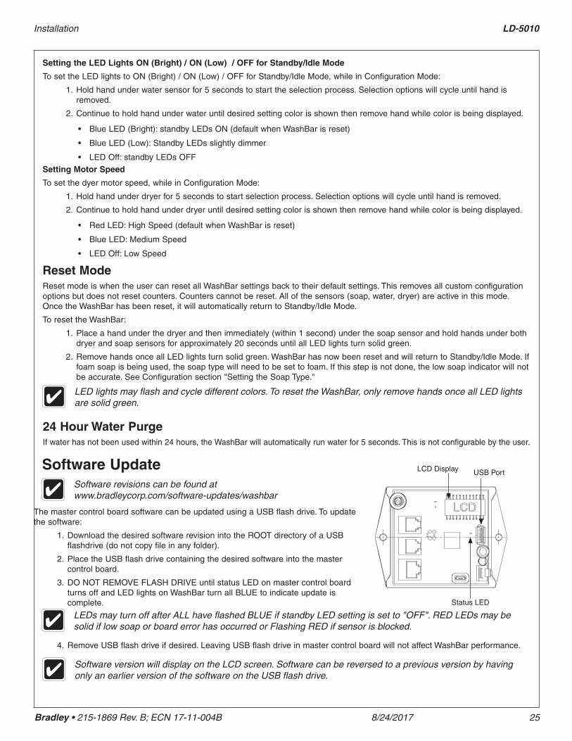
Software Update
Reset ModeReset mode is when the user can reset all WashBar settings back to their default settings. This removes all custom configuration options but does not reset counters. Counters cannot be reset. All of the sensors (soap, water, dryer) are active in this mode. Once the WashBar has been reset, it will automatically return to Standby/Idle Mode.
To reset the WashBar:
1. Place a hand under the dryer and then immediately (within 1 second) under the soap sensor and hold hands under both dryer and soap sensors for approximately 20 seconds until all LED lights turn solid green.
2. Remove hands once all LED lights turn solid green. WashBar has now been reset and will return to Standby/Idle Mode. If foam soap is being used, the soap type will need to be set to foam. If this step is not done, the low soap indicator will not be accurate. See Configuration section "Setting the Soap Type."
LED lights may flash and cycle different colors. To reset the WashBar, only remove hands once all LED lights are solid green.
Software version will display on the LCD screen. Software can be reversed to a previous version by having only an earlier version of the software on the USB flash drive.
Setting the LED Lights ON (Bright) / ON (Low) / OFF for Standby/Idle Mode
To set the LED lights to ON (Bright) / ON (Low) / OFF for Standby/Idle Mode, while in Configuration Mode:
1. Hold hand under water sensor for 5 seconds to start the selection process. Selection options will cycle until hand is removed.
2. Continue to hold hand under water until desired setting color is shown then remove hand while color is being displayed.
• Blue LED (Bright): standby LEDs ON (default when WashBar is reset)
• Blue LED (Low): Standby LEDs slightly dimmer
• LED Off: standby LEDs OFFSetting Motor Speed
To set the dyer motor speed, while in Configuration Mode:
1. Hold hand under dryer for 5 seconds to start selection process. Selection options will cycle until hand is removed.
2. Continue to hold hand under dryer until desired setting color is shown then remove hand while color is being displayed.
• Red LED: High Speed (default when WashBar is reset)
• Blue LED: Medium Speed
• LED Off: Low Speed
LCD Display USB Port
Status LED
24 Hour Water PurgeIf water has not been used within 24 hours, the WashBar will automatically run water for 5 seconds. This is not configurable by the user.
The master control board software can be updated using a USB flash drive. To update the software:
1. Download the desired software revision into the ROOT directory of a USB flashdrive (do not copy file in any folder).
2. Place the USB flash drive containing the desired software into the master control board.
3. DO NOT REMOVE FLASH DRIVE until status LED on master control board turns off and LED lights on WashBar turn all BLUE to indicate update is complete.
Software revisions can be found at www.bradleycorp.com/software-updates/washbar
4. Remove USB flash drive if desired. Leaving USB flash drive in master control board will not affect WashBar performance.
LEDs may turn off after ALL have flashed BLUE if standby LED setting is set to "OFF". RED LEDs may be solid if low soap or board error has occurred or Flashing RED if sensor is blocked.

LD-5010 Installation
26 8/24/2017 Bradley • 215-1869 Rev. B; ECN 17-11-004B
Displaying Software Revision and Cycle Counts on LCD DisplayThe master control board has an LCD screen that continuously displays information about the software version and cycle counts for the soap, water and dryer. To view the LCD display:
5. Open the access panel.
6. Locate the LCD screen on the master control board. The display will cycle through the software revision and counts. Cycle counts are displayed x1000 (ex. 65 = 65,000)
• REV followed by the software revision
• SOP followed by the soap cycle count
• H2O followed by the water cycle count
• AIR followed by the dryer cycle count

Installation LD-5010
Bradley • 215-1869 Rev. B; ECN 17-11-004B 8/24/2017 27
Cleaning and Maintenance for Terreon®
Material Description: Terreon is a densified solid surface material composed of bio based resin and is resistant to chemicals, stains, burns and impact. Surface can be easily repaired with everyday cleansers or fine grit abrasives. Because Terreon is a unique cast material, its aggregate flow and distribution, and shades of color can vary from product to product creating natural characteristics.
Routine Cleaning: For regular cleaning, use mild neutral base cleaners.
Stubborn Stains: Remove tough stains with Soft-Scrub® and a green Scotch-Brite® pad or lightly sand in a circular motion with 240 grit wet/dry sandpaper. The finish can then be renewed with a maroon Scotch-Brite pad.
Scratches: Remove scratches with a green Scotch-Brite pad. The finish can then be renewed with a maroon Scotch-Brite pad.
Hard Water Deposits: Remove hard water deposits with a mild solution of vinegar and water. Always rinse the unit thoroughly after cleaning.
Restoring the surface: Use Hope’s® Perfect Countertop to refresh and protect the Terreon Solid Surface material. Dark Terreon colors may require additional care and maintenance. For complete instructions on this additional maintenance, visit bradleycorp.com.
Repair Kits: Terreon repair kits are available. Contact your Bradley representative or distributor for part numbers and pricing. Repair kits are made to order and have a shelf life of 30 days.
NOTICE! Do not use strong acid or alkaline chemicals and cleaners to clean Terreon. If these chemicals come in contact with the surface, wipe them off immediately and rinse with soapy water. Avoid contact with harsh chemicals such as paint remover, bleach, acetone, etc. Avoid contact with hot pans and objects.
Cleaning and Maintenance for Stainless SteelMaterial Description: Stainless steel is extremely durable, and maintenance is simple and inexpensive. Proper care, particularly under corrosive conditions, is essential. Always start with the simplest solution and work your way toward the more complicated.
Routine cleaning: Daily or as often as needed use a solution of warm water and soap, detergent, or ammonia. Apply the cleaning solution per the manufacturer's instructions and always use a soft cloth or sponge to avoid damaging the finish.
Stubborn Stains: To remove stains from stainless steel use a stainless steel cleaner and polish such as Ball® stainless steel cleaner or a soft abrasive. Always follow the manufacturer's instructions and apply in the same direction as the polish lines.
NOTICE! Never use ordinary steel wool or steel brushes on stainless steel. Always use stainless steel wool or stainless steel brushes.
Fingerprints and Smears: To remove fingerprints or smears use a high quality stainless steel cleaner and polish in accordance with the manufacturer's instructions. Many of these products leave a protective coating that helps prevent future smears and fingerprints.
Grease and Oil: To remove grease and oil use a quality commercial detergent or caustic cleaner. Apply in accordance to the manufacturer's instructions and in the direction of the polish lines.
Precautions: Avoid prolonged contact with chlorides (bleaches, salts), bromides (sanitizing agents), thiocyanates (pesticides, photography chemicals, and some foods), and iodides on stainless steel equipment, especially if acid conditions exist.
NOTICE! Do not permit salty solutions to evaporate and dry on stainless steel.
The appearance of rust streaks on stainless steel leads to the belief that the stainless steel is rusting. Look for the actual source of the rust in some iron or steel particles which may be touching, but not actually a part of the stainless steel structure.
NOTICE! Strongly acidic or caustic cleaners may attack the steel causing a reddish film to appear. The use of these cleaners should be avoided.
Brand NamesUse of brand names is intended only to indicate a type of cleaner. This does not constitute an endorsement, nor does the omission of any brand name cleaner imply inadequacy. Many products named are regional in distribution, and can be found in local supermarkets, department and hardware stores, or through your cleaning service. It is emphasized that all products should be used in strict accordance with package instructions.
LD-5010 Installation
28 8/24/2017 Bradley • 215-1869 Rev. B; ECN 17-11-004B
Liquid Soap Recommendations and Dispenser MaintenanceOverview
Quality soap dispensers require good quality soap and periodic maintenance to properly operate. Bradley soap dispensers will provide dependable, consistent operation over the long term when soap with reasonable viscosity and pH levels are used and when a minimal amount of periodic maintenance is performed on the valves. Most soap dispenser problems are caused by soap that is too thick or corrosive, or by a lack of maintenance. Many soaps come in concentrate form which must be diluted with water. Often, the soap is improperly diluted or used straight out of the bottle, which causes clogging and valve failure. If proper soap is being used, valves that have never been cleaned are usually the source of dispensing problems. With proper maintenance and soap, Bradley dispensers will provide long term, trouble free operation.
ViscositySoap thickness is determined by a measurement called viscosity. Soap viscosity should be between 100 cps (centipoise) and 2500 cps for all Bradley soap dispensers. Thick soaps flow slower and inhibit the “flushing” action of the valves, which allows the soap to congeal in the valve and cause clogs.
pH LevelThe pH (acid) level of the soap should be in the range of 6.5 to 8.5. More acidic soaps (pH levels lower than 6.5) will corrode metal parts (even stainless steel!!) and degrade rubber and plastic components. They will also cause skin irritation. Most inexpensive soaps (typically the pink lotion type) fall into this acidic category and will eventually cause valve failure and metal corrosion.
CAUTION Base soaps (pH levels higher than 8.5) will cause skin irritation and swelling or degradation of rubber and plastic parts.
Soap ValvesValves must also be maintained (cleaned) to function properly. At the very minimum, hot water should be pumped through valves periodically to clear out soap residue. Ideally, valves should occasionally be soaked for 30 minutes in hot water or a soap valve cleaning solution. The valve should be pumped at least 20 times while it is soaking to clear any clogs. The soap reservoir should also be flushed with hot water. In cases of extreme clogging, the valve should be disassembled and the parts should be soaked in hot water or cleaning solution to restore proper functioning. Generally, any quality soap meeting the viscosity and pH guidelines above will work well with Bradley soap dispensers. PCMX or Isopropanol based antibacterial soaps (within viscosity and pH limits) will also work with Bradley dispensers. Soaps satisfying these basic guidelines will provide consistent flow and reduce clogs.
Cleaning and Maintenance for WashBarWipe top and underside of WashBar with a mild neutral based cleaner. Dry with a soft cloth to avoid micro scratches in the WashBar finish and sensor plates.
Cleaning and Maintenance for Trench DrainDepending on application and usage, it is recommended that the drain cap and strainer be removed for regular trench drain cleaning 2-3 times a month.