INSTALLATION AND SERVICE MUST BE …c.sears.com/assets/misc/41003e.pdfINSTALLATION AND SERVICE MUST...
20
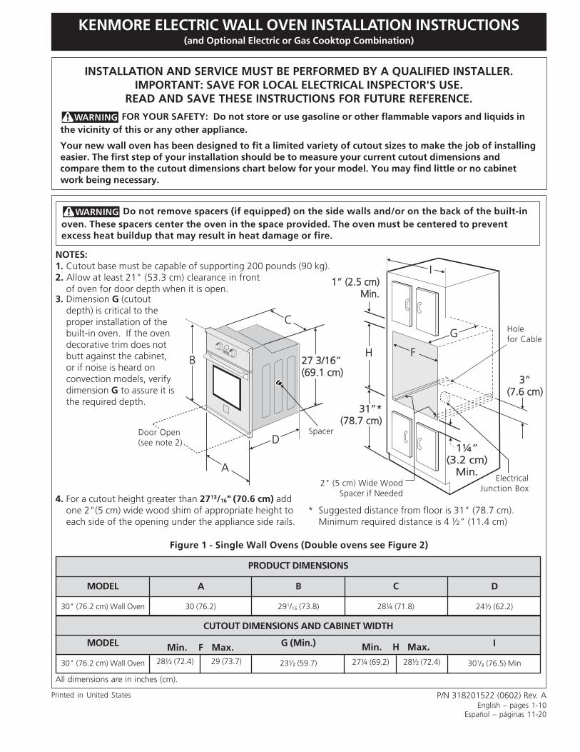
KENMORE ELECTRIC WALL OVEN INSTALLATION INSTRUCTIONS (and Optional Electric or Gas Cooktop Combination) H F I G 1¼” (3.2 cm) Min. 1¼” (3.2 cm) Min. 31”* (78.7 cm) 31”* (78.7 cm) 3” (7.6 cm) 3” (7.6 cm) 1” (2.5 cm) Min. 1” (2.5 cm) Min. B A D C 27 3/16” (69.1 cm) 27 3/16” (69.1 cm) INSTALLATION AND SERVICE MUST BE PERFORMED BY A QUALIFIED INSTALLER. IMPORTANT: SAVE FOR LOCAL ELECTRICAL INSPECTOR'S USE. READ AND SAVE THESE INSTRUCTIONS FOR FUTURE REFERENCE. FOR YOUR SAFETY: Do not store or use gasoline or other flammable vapors and liquids in the vicinity of this or any other appliance. Your new wall oven has been designed to fit a limited variety of cutout sizes to make the job of installing easier. The first step of your installation should be to measure your current cutout dimensions and compare them to the cutout dimensions chart below for your model. You may find little or no cabinet work being necessary. Figure 1 - Single Wall Ovens (Double ovens see Figure 2) P/N 318201522 (0602) Rev. A English – pages 1-10 Español – páginas 11-20 All dimensions are in inches (cm). Do not remove spacers (if equipped) on the side walls and/or on the back of the built-in oven. These spacers center the oven in the space provided. The oven must be centered to prevent excess heat buildup that may result in heat damage or fire. 2" (5 cm) Wide Wood Spacer if Needed NOTES: 1. Cutout base must be capable of supporting 200 pounds (90 kg). 2. Allow at least 21" (53.3 cm) clearance in front of oven for door depth when it is open. Door Open (see note 2) Spacer Electrical Junction Box Hole for Cable Printed in United States PRODUCT DIMENSIONS CUTOUT DIMENSIONS AND CABINET WIDTH Min. F Max. Min. H Max. MODEL 30" (76.2 cm) Wall Oven MODEL 30" (76.2 cm) Wall Oven A 30 (76.2) B 29 1 /16 (73.8) G (Min.) 23½ (59.7) C 28¼ (71.8) D 24½ (62.2) I 30 1 /8 (76.5) Min 28½ (72.4) 29 (73.7) 27¼ (69.2) 28½ (72.4) 3. Dimension G (cutout depth) is critical to the proper installation of the built-in oven. If the oven decorative trim does not butt against the cabinet, or if noise is heard on convection models, verify dimension G to assure it is the required depth. * Suggested distance from floor is 31" (78.7 cm). Minimum required distance is 4 ½" (11.4 cm) 4. For a cutout height greater than 27 13 /16" (70.6 cm) add one 2"(5 cm) wide wood shim of appropriate height to each side of the opening under the appliance side rails.
Transcript of INSTALLATION AND SERVICE MUST BE …c.sears.com/assets/misc/41003e.pdfINSTALLATION AND SERVICE MUST...
1
KENMORE ELECTRIC WALL OVEN INSTALLATION INSTRUCTIONS(and Optional Electric or Gas Cooktop Combination)
H F
I
G
1¼”(3.2 cm)
Min.
1¼”(3.2 cm)
Min.
31”*(78.7 cm)
31”*(78.7 cm)
3”(7.6 cm)
3”(7.6 cm)
1” (2.5 cm)Min.
1” (2.5 cm)Min.
B
A
D
C
27 3/16”(69.1 cm)27 3/16”(69.1 cm)
INSTALLATION AND SERVICE MUST BE PERFORMED BY A QUALIFIED INSTALLER.IMPORTANT: SAVE FOR LOCAL ELECTRICAL INSPECTOR'S USE.
READ AND SAVE THESE INSTRUCTIONS FOR FUTURE REFERENCE.
FOR YOUR SAFETY: Do not store or use gasoline or other flammable vapors and liquids inthe vicinity of this or any other appliance.
Your new wall oven has been designed to fit a limited variety of cutout sizes to make the job of installingeasier. The first step of your installation should be to measure your current cutout dimensions andcompare them to the cutout dimensions chart below for your model. You may find little or no cabinetwork being necessary.
Figure 1 - Single Wall Ovens (Double ovens see Figure 2)
P/N 318201522 (0602) Rev. AEnglish – pages 1-10
Español – páginas 11-20
All dimensions are in inches (cm).
Do not remove spacers (if equipped) on the side walls and/or on the back of the built-inoven. These spacers center the oven in the space provided. The oven must be centered to preventexcess heat buildup that may result in heat damage or fire.
2" (5 cm) Wide WoodSpacer if Needed
NOTES:1. Cutout base must be capable of supporting 200 pounds (90 kg).2. Allow at least 21" (53.3 cm) clearance in front
of oven for door depth when it is open.
Door Open(see note 2)
Spacer
ElectricalJunction Box
Holefor Cable
Printed in United States
PRODUCT DIMENSIONS
CUTOUT DIMENSIONS AND CABINET WIDTH
Min. F Max. Min. H Max.
MODEL
30" (76.2 cm) Wall Oven
MODEL
30" (76.2 cm) Wall Oven
A
30 (76.2)
B
291/16 (73.8)
G (Min.)
23½ (59.7)
C
28¼ (71.8)
D
24½ (62.2)
I
301/8 (76.5) Min28½ (72.4) 29 (73.7) 27¼ (69.2) 28½ (72.4)
3. Dimension G (cutoutdepth) is critical to theproper installation of thebuilt-in oven. If the ovendecorative trim does notbutt against the cabinet,or if noise is heard onconvection models, verifydimension G to assure it isthe required depth.
* Suggested distance from floor is 31" (78.7 cm).Minimum required distance is 4 ½" (11.4 cm)
4. For a cutout height greater than 2713/16" (70.6 cm) addone 2"(5 cm) wide wood shim of appropriate height toeach side of the opening under the appliance side rails.
2
KENMORE ELECTRIC WALL OVEN INSTALLATION INSTRUCTIONS(and Optional Electric or Gas Cooktop Combination)
F
I
H
G
11½”(29.2 cm)
11½”(29.2 cm)
1¼”(3.2 cm)Min.
1¼”(3.2 cm)Min.
3” (7.6 cm)Max.
3” (7.6 cm)Max.
1” (2.5 cm)Min.
1” (2.5 cm)Min.
B
A
D
C
48 5/8”(123.5 cm)48 5/8”(123.5 cm)
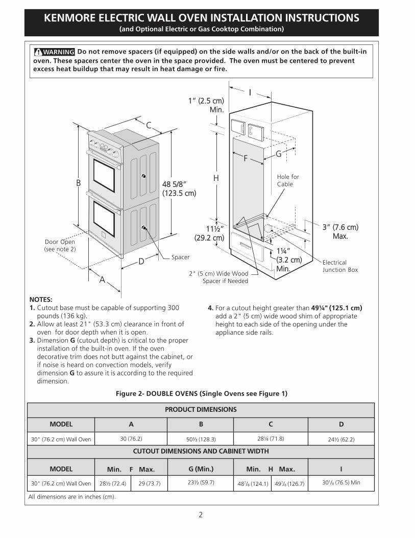
Figure 2- DOUBLE OVENS (Single Ovens see Figure 1)
Do not remove spacers (if equipped) on the side walls and/or on the back of the built-inoven. These spacers center the oven in the space provided. The oven must be centered to preventexcess heat buildup that may result in heat damage or fire.
All dimensions are in inches (cm).
NOTES:1. Cutout base must be capable of supporting 300
pounds (136 kg).2. Allow at least 21" (53.3 cm) clearance in front of
oven for door depth when it is open.3. Dimension G (cutout depth) is critical to the proper
installation of the built-in oven. If the ovendecorative trim does not butt against the cabinet, orif noise is heard on convection models, verifydimension G to assure it is according to the requireddimension.
4. For a cutout height greater than 49¼" (125.1 cm)add a 2" (5 cm) wide wood shim of appropriateheight to each side of the opening under theappliance side rails.
Door Open(see note 2)
Hole forCable
ElectricalJunction Box
2" (5 cm) Wide WoodSpacer if Needed
Spacer
PRODUCT DIMENSIONS
CUTOUT DIMENSIONS AND CABINET WIDTH
Min. F Max. Min. H Max.
MODEL
30" (76.2 cm) Wall Oven
MODEL
30" (76.2 cm) Wall Oven
A
30 (76.2)
B
50½ (128.3)
G (Min.)
23½ (59.7)
C
28¼ (71.8)
D
24½ (62.2)
I
301/8 (76.5) Min28½ (72.4) 29 (73.7) 487/8 (124.1) 497/8 (126.7)
3
KENMORE ELECTRIC WALL OVEN INSTALLATION INSTRUCTIONS(and Optional Electric or Gas Cooktop Combination)
Important Notes to the Installer1. Read all instructions contained in these installation
instructions before installing the wall oven.2. Remove all packing material from the oven
compartments before connecting the electrical supplyto the wall oven.
3. Observe all governing codes and ordinances.4. Be sure to leave these instructions with the consumer.5. Oven door may be removed to facilitate installation.6. THESE OVENS ARE NOT APPROVED FOR
STACKABLE OR SIDE-BY-SIDE INSTALLATION.
Important Note to the ConsumerKeep these instructions with your Owner's Guide for futurereference.
IMPORTANT SAFETYINSTRUCTIONS• Be sure your wall oven is installed and grounded
properly by a qualified installer or servicetechnician.
• This wall oven must be electrically grounded inaccordance with local codes or, in their absence,with the National Electrical Code ANSI/NFPANo.70- latest edition in United Sates, or with CSAStandard C22.1, Canadian Electrical Code, Part 1, inCanada.
Stepping, leaning or sitting on thedoor of this wall oven can result in serious injuriesand can also cause damage to the wall oven.
• Never use your wall oven for warming or heatingthe room. Prolonged use of the wall oven withoutadequate ventilation can be dangerous.
The electrical power to the oven mustbe shut off while line connections are being made.Failure to do so could result in serious injury ordeath.
1. CarpentryRefer to figure 1 or 2 for the dimensions applicable toyour appliance, and the space necessary to receive theoven. The oven support surface (cutout base) may besolid plywood or similar material, however the surfacemust be level from side to side and from front to rear.
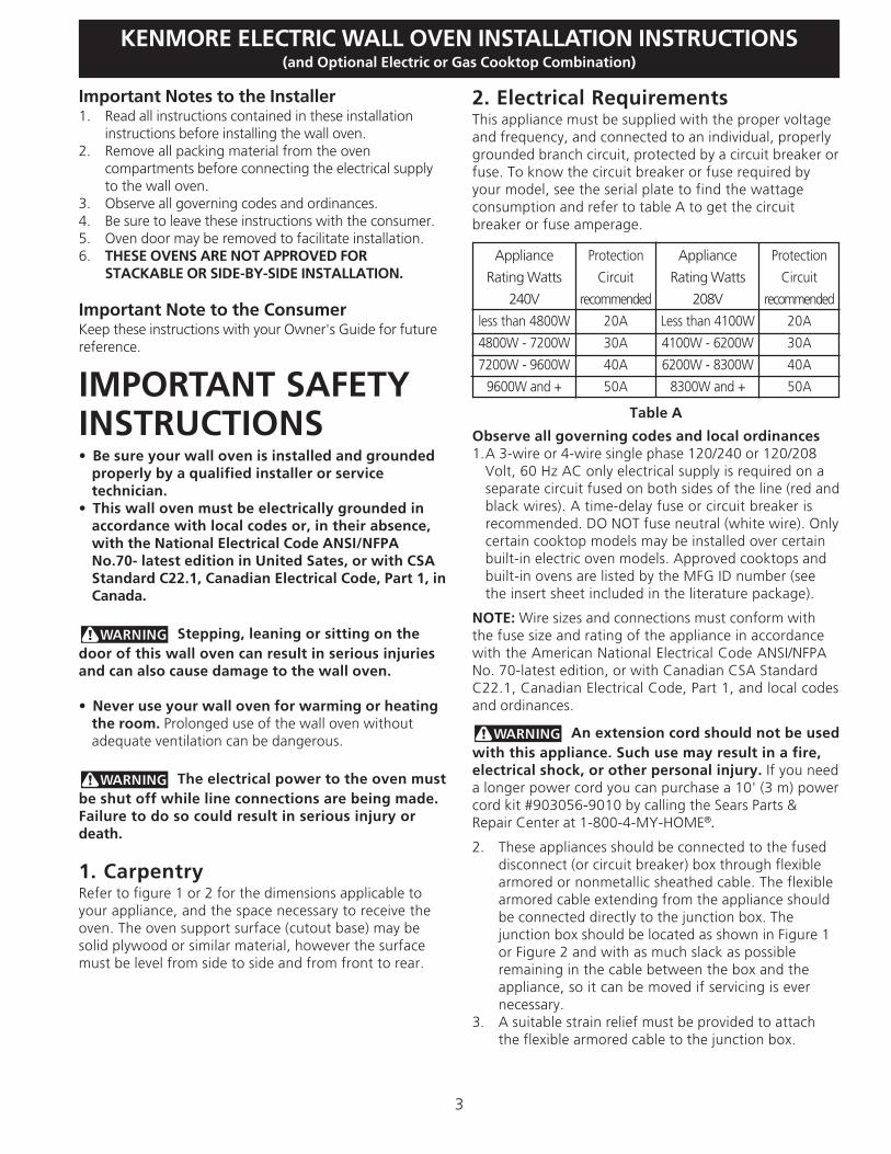
2. Electrical RequirementsThis appliance must be supplied with the proper voltageand frequency, and connected to an individual, properlygrounded branch circuit, protected by a circuit breaker orfuse. To know the circuit breaker or fuse required byyour model, see the serial plate to find the wattageconsumption and refer to table A to get the circuitbreaker or fuse amperage.
Appliance
Rating Watts
240V
less than 4800W
4800W - 7200W
7200W - 9600W
9600W and +
Protection
Circuit
recommended
20A
30A
40A
50A
Appliance
Rating Watts
208V
Less than 4100W
4100W - 6200W
6200W - 8300W
8300W and +
Protection
Circuit
recommended
20A
30A
40A
50A
Table A
Observe all governing codes and local ordinances1.A 3-wire or 4-wire single phase 120/240 or 120/208
Volt, 60 Hz AC only electrical supply is required on aseparate circuit fused on both sides of the line (red andblack wires). A time-delay fuse or circuit breaker isrecommended. DO NOT fuse neutral (white wire). Onlycertain cooktop models may be installed over certainbuilt-in electric oven models. Approved cooktops andbuilt-in ovens are listed by the MFG ID number (seethe insert sheet included in the literature package).
NOTE: Wire sizes and connections must conform withthe fuse size and rating of the appliance in accordancewith the American National Electrical Code ANSI/NFPANo. 70-latest edition, or with Canadian CSA StandardC22.1, Canadian Electrical Code, Part 1, and local codesand ordinances.
An extension cord should not be usedwith this appliance. Such use may result in a fire,electrical shock, or other personal injury. If you needa longer power cord you can purchase a 10' (3 m) powercord kit #903056-9010 by calling the Sears Parts &Repair Center at 1-800-4-MY-HOME®.
2. These appliances should be connected to the fuseddisconnect (or circuit breaker) box through flexiblearmored or nonmetallic sheathed cable. The flexiblearmored cable extending from the appliance shouldbe connected directly to the junction box. Thejunction box should be located as shown in Figure 1or Figure 2 and with as much slack as possibleremaining in the cable between the box and theappliance, so it can be moved if servicing is evernecessary.
3. A suitable strain relief must be provided to attachthe flexible armored cable to the junction box.

4
KENMORE ELECTRIC WALL OVEN INSTALLATION INSTRUCTIONS(and Optional Electric or Gas Cooktop Combination)
In cold weather shipping and storageconditions, make sure that oven is in final location atleast three (3) hours before switching on power.Switching on power while oven is still cold may damagethe oven controls.
3. Adjusting Oven HeightOven height can be adjusted with 2" (5 cm) wide woodshims when needed to fit into an existing cabinet cutoutopening, when cutout height exceeds 2713/16" (70.6 cm)for the single wall oven or 49¼" (125.1 cm) for thedouble wall oven (see Figure 1 or 2). Place shims ofappropriate height beneath the oven side rails.
4. Electrical connectionIt is the responsibility and obligation of the consumer tocontact a qualified installer to assure that the electricalinstallation is adequate and is in conformance with theNational Electrical Code ANSI/NFPA No. 70-latestedition, or with CSA Standard C22.1, CanadianElectrical Code, Part 1, and local codes and ordinances.
Electrical ground is required on this appliance.
These appliances are equipped with a copper conductorflexible cable. If connection is made to aluminum housewiring, use only special connectors which are approvedfor joining copper and aluminum wires in accordancewith National Electrical Code and local codes andordinances.
These appliances are manufactured with a white neutralpower supply wire and a frame connected green or barecopper grounding wire.
Where local codes permit connecting the appliancecable ground wire to the power supply cableneutral (white) wire (see figure 3):1. Disconnect the power supply.2. In the circuit breaker, fuse box or junction box:
connect appliance and power supply cable wires asshown in Figure 3.
Improper connection of aluminumhouse wiring to copper leads can result in a shortcircuit or fire. Use only connectors designed forjoining copper to aluminum, and follow themanufacturer's recommended procedure closely.
Electrical Shock Hazard• Electrical ground is required on this appliance.• Do not connect to the electrical supply until
appliance is permanently grounded.• Disconnect power to the junction box before
making the electrical connection.• This appliance must be connected to a
grounded, metallic, permanent wiring system,or a grounding connector should be connectedto the grounding terminal or wire lead on theappliance.
• Do not use a gas supply line for grounding theappliance.
Failure to do any of the above could result in afire, personal injury or electrical shock.
Figure 3 - 3-WIRE GROUNDED JUNCTION BOX
Cable from Power Supply
BlackWires
JunctionBox
Cable from appliance
Ground Wire(Bare or Green Wire)
White Wire(Neutral)
U.L.-Listed ConduitConnector (or CSA listed)
RedWires
White Wire(Neutral)
5
KENMORE ELECTRIC WALL OVEN INSTALLATION INSTRUCTIONS(and Optional Electric or Gas Cooktop Combination)
You may not ground the oventhrough the neutral (white) wire if oven is used ina new branch circuit installation (1996 NEC), mobilehome, recreational vehicle, or where local codes donot permit grounding through the neutral (white)wire. When grounding through the neutral (white)wire is prohibited, you must use a 4-wire powersupply cable. See Figure 4. Failure to heed thiswarning may result in electrocution or otherserious personal injury.
If oven is used in a new branch circuit installation(1996 NEC), mobile home, recreational vehicle, orwhere local codes DO NOT permit connecting theappliance cable ground wire to the power supplycable neutral (white) wire, you must use a 4-wirepower supply cable (see figure 4):1. Disconnect the power supply.2. In the circuit breaker, fuse box or junction box:
connect appliance and power supply cable wires asshown in Figure 4.
DO NOT ground to a gas supply pipe. DO NOT connectto electrical power supply until appliance is permanentlygrounded. Connect the ground wire before turning onthe power (Figure 4).
If connecting to a 4-wire electricalsystem (mobile homes), the appliance frame MUSTNOT be connected to the neutral wire of the 4-wireelectrical system.
NOTE TO ELECTRICIAN: The armored cable leadssupplied with the appliance are UL-recognized forconnection to larger gauge household wiring. Theinsulation of the leads is rated at temperatures muchhigher than temperature rating of household wiring. Thecurrent carrying capacity of the conductor is governed bythe temperature rating of the insulation around the wire,rather than the wire gauge alone.
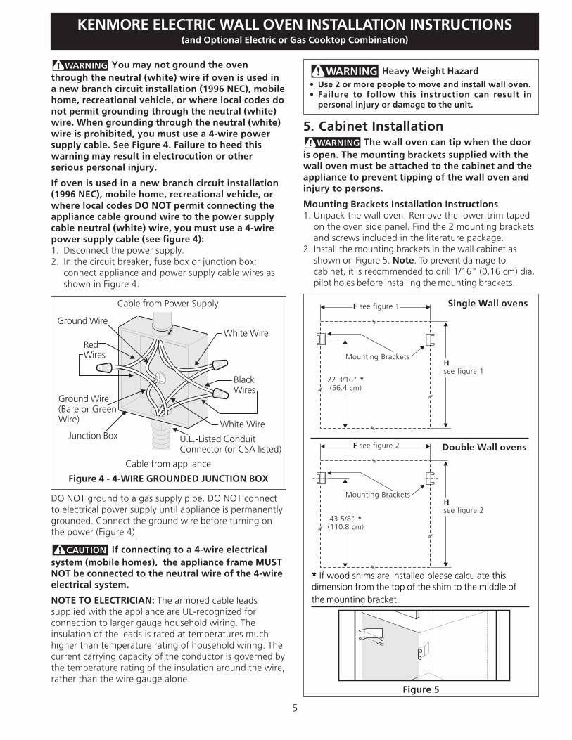
5. Cabinet Installation The wall oven can tip when the door
is open. The mounting brackets supplied with thewall oven must be attached to the cabinet and theappliance to prevent tipping of the wall oven andinjury to persons.
Mounting Brackets Installation Instructions1. Unpack the wall oven. Remove the lower trim taped
on the oven side panel. Find the 2 mounting bracketsand screws included in the literature package.
2. Install the mounting brackets in the wall cabinet asshown on Figure 5. Note: To prevent damage tocabinet, it is recommended to drill 1/16" (0.16 cm) dia.pilot holes before installing the mounting brackets.
Figure 4 - 4-WIRE GROUNDED JUNCTION BOX
Cable from Power Supply
White WireJunction Box
Cable from appliance
White Wire
BlackWires
RedWires
Ground Wire
Ground Wire(Bare or GreenWire)
U.L.-Listed ConduitConnector (or CSA listed)
Figure 5
Mounting Brackets
43 5/8" *(110.8 cm)
Hsee figure 2
F see figure 2 Double Wall ovens
Mounting Brackets
22 3/16" *(56.4 cm)
Hsee figure 1
F see figure 1 Single Wall ovens
* If wood shims are installed please calculate thisdimension from the top of the shim to the middle ofthe mounting bracket.
Heavy Weight Hazard• Use 2 or more people to move and install wall oven.• Failure to follow this instruction can result in
personal injury or damage to the unit.
6
KENMORE ELECTRIC WALL OVEN INSTALLATION INSTRUCTIONS(and Optional Electric or Gas Cooktop Combination)
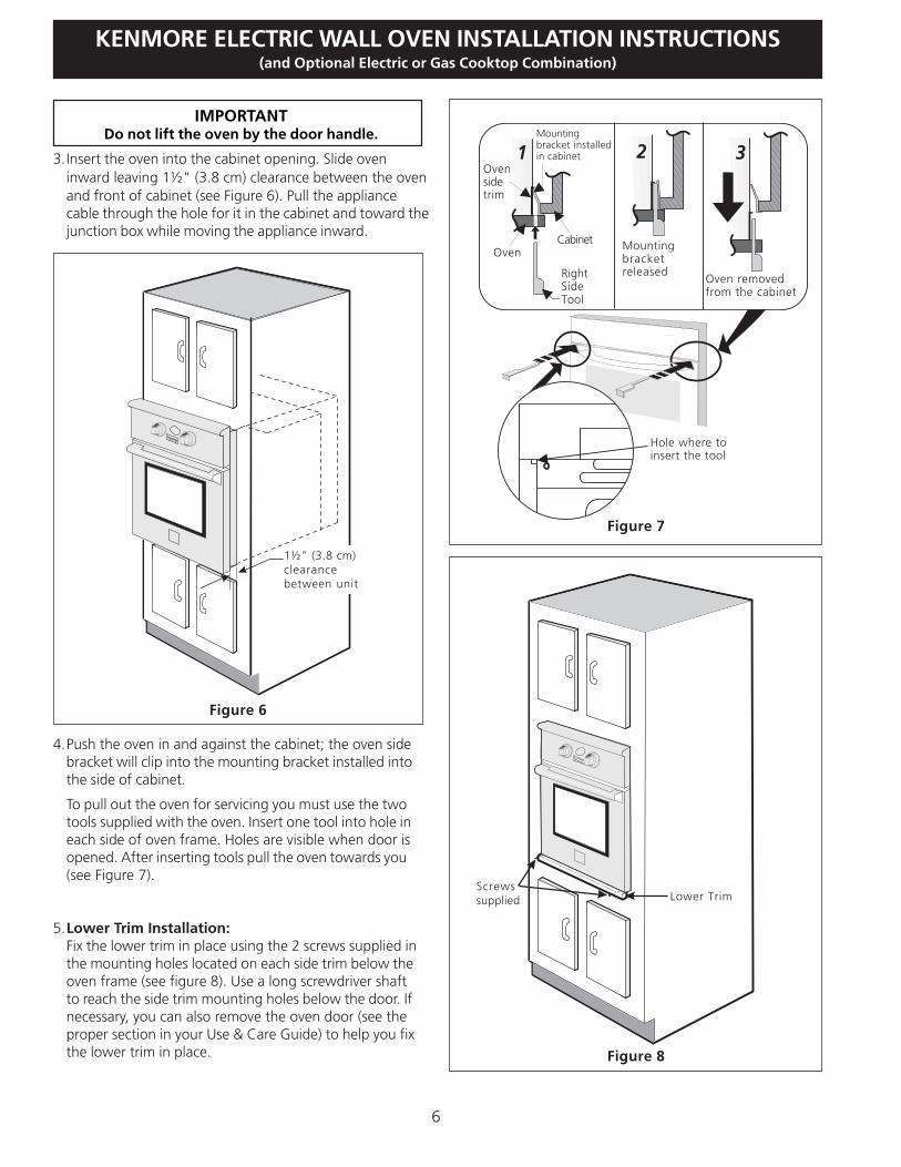
IMPORTANTDo not lift the oven by the door handle.
3.Insert the oven into the cabinet opening. Slide oveninward leaving 1½" (3.8 cm) clearance between the ovenand front of cabinet (see Figure 6). Pull the appliancecable through the hole for it in the cabinet and toward thejunction box while moving the appliance inward.
4.Push the oven in and against the cabinet; the oven sidebracket will clip into the mounting bracket installed intothe side of cabinet.
To pull out the oven for servicing you must use the twotools supplied with the oven. Insert one tool into hole ineach side of oven frame. Holes are visible when door isopened. After inserting tools pull the oven towards you(see Figure 7).
5.Lower Trim Installation:Fix the lower trim in place using the 2 screws supplied inthe mounting holes located on each side trim below theoven frame (see figure 8). Use a long screwdriver shaftto reach the side trim mounting holes below the door. Ifnecessary, you can also remove the oven door (see theproper section in your Use & Care Guide) to help you fixthe lower trim in place.
Figure 6
1½" (3.8 cm)clearancebetween unit
Figure 7
1 2 3Mountingbracket installedin cabinet
Oven
RightSideTool
Mountingbracketreleased
Cabinet
Oven removedfrom the cabinet
Hole where toinsert the tool
Ovensidetrim
Figure 8
Lower TrimScrewssupplied

7
KENMORE ELECTRIC WALL OVEN INSTALLATION INSTRUCTIONS(and Optional Electric or Gas Cooktop Combination)
Only certain cooktop models may be installed over cer-tain built-in electric oven models. Approved cooktopsand built-in ovens are listed by the MFG ID number andproduct code (see the insert sheet included in the litera-ture package and cooktop installation instructions for thedimensions).
G
F
H
36” Min.(91.4 cm) Min.
Use 3/4” (1.9 cm) plywood, installedon two runners, flush with toe plate.Base must be capable of supporting200 pounds (90 kg).
Cut an opening in wood base minimum 9” x 9”(23 X 23 cm), 2” (5 cm) from left side fillerpanel, to route armoured cable to junction box.
208/240 Volt junction boxfor built-in oven.
Figure 9 - TYPICAL UNDER COUNTER INSTALLATION OF A SINGLE ELECTRIC BUILT-IN OVENWITH AN ELECTRIC COOKTOP MOUNTED ABOVE
Approx. 3”(7.5 cm)
Cabinet side filler panels arenecessary to isolate the unitfrom adjoining cabinets. Cabinetside filler height should allow forinstallation of approved cooktopmodels
To reduce the risk ofpersonal injury andtipping of the walloven, the wall ovenmust be secured tothe cabinet (s) bymounting brackets.
4-1/2” (11.5 cm) Max. distance** If no cooktop is installed directly over
the oven unit, 5” (12.7 cm) maximumis allowed above the floor.
6.For typical under counter installation of an electric built-in oven see Figure below.
CUTOUT DIMENSIONS
F.WIDTH G.DEPTH H.HEIGHT
30" (76.2 cm)Wall Oven
28½" (72.4 cm) Min.29" (73.7 cm) Max. 23½" (59.7 cm) Min.
27¼" (69.2 cm) Min.28½" (72.4 cm) Max.

8
KENMORE ELECTRIC WALL OVEN INSTALLATION INSTRUCTIONS(and Optional Electric or Gas Cooktop Combination)
Figure 10 - TYPICAL UNDER COUNTER INSTALLATION OF A SINGLE ELECTRIC BUILT-IN OVENWITH A GAS COOKTOP ABOVE
18”(45.7 cm) Max.
6 1/2” Min.(16.5 cm)
FlareUnion
4”(10 cm)
120V/60HzGrounded
Outlet
PressureRegulator
Flexible Appliance Conduit
Wall Oven Cabinetside or filler panel
Wall Oven Cabinet
5” Max.(12.7 cm)
FlareUnion
Manual Shutoff Valve(To be accessible for shut-off
valve operation)
9
KENMORE ELECTRIC WALL OVEN INSTALLATION INSTRUCTIONS(and Optional Electric or Gas Cooktop Combination)
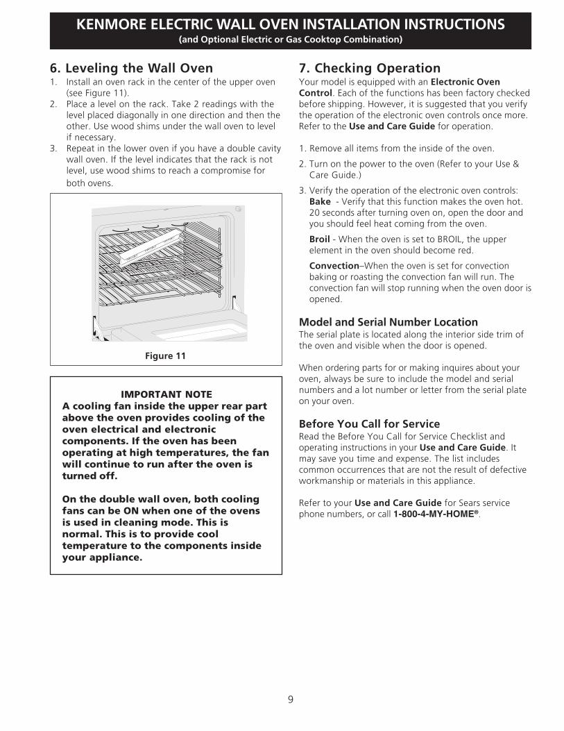
IMPORTANT NOTEA cooling fan inside the upper rear partabove the oven provides cooling of theoven electrical and electroniccomponents. If the oven has beenoperating at high temperatures, the fanwill continue to run after the oven isturned off.
On the double wall oven, both coolingfans can be ON when one of the ovensis used in cleaning mode. This isnormal. This is to provide cooltemperature to the components insideyour appliance.
7. Checking OperationYour model is equipped with an Electronic OvenControl. Each of the functions has been factory checkedbefore shipping. However, it is suggested that you verifythe operation of the electronic oven controls once more.Refer to the Use and Care Guide for operation.
1. Remove all items from the inside of the oven.
2. Turn on the power to the oven (Refer to your Use &Care Guide.)
3. Verify the operation of the electronic oven controls:Bake - Verify that this function makes the oven hot.20 seconds after turning oven on, open the door andyou should feel heat coming from the oven.
Broil - When the oven is set to BROIL, the upperelement in the oven should become red.
Convection–When the oven is set for convectionbaking or roasting the convection fan will run. Theconvection fan will stop running when the oven door isopened.
Model and Serial Number LocationThe serial plate is located along the interior side trim ofthe oven and visible when the door is opened.
When ordering parts for or making inquires about youroven, always be sure to include the model and serialnumbers and a lot number or letter from the serial plateon your oven.
Before You Call for ServiceRead the Before You Call for Service Checklist andoperating instructions in your Use and Care Guide. Itmay save you time and expense. The list includescommon occurrences that are not the result of defectiveworkmanship or materials in this appliance.
Refer to your Use and Care Guide for Sears servicephone numbers, or call 1-800-4-MY-HOME®.
6. Leveling the Wall Oven1. Install an oven rack in the center of the upper oven
(see Figure 11).2. Place a level on the rack. Take 2 readings with the
level placed diagonally in one direction and then theother. Use wood shims under the wall oven to levelif necessary.
3. Repeat in the lower oven if you have a double cavitywall oven. If the level indicates that the rack is notlevel, use wood shims to reach a compromise forboth ovens.
Figure 11

10
KENMORE ELECTRIC WALL OVEN INSTALLATION INSTRUCTIONS(and Optional Electric or Gas Cooktop Combination)
Notes

11
INSTRUCCIONES DE INSTALACIÓN PARA EL HORNO ELECTRICO DE PARED KENMORE(Combinado con una cocina electrica o de gas facultativa)
H F
I
G
1¼”(3.2 cm)
Min.
1¼”(3.2 cm)
Min.
31”*(78.7 cm)
31”*(78.7 cm)
3”(7.6 cm)
3”(7.6 cm)
1” (2.5 cm)Min.
1” (2.5 cm)Min.
B
A
D
C
27 3/16”(69.1 cm)27 3/16”(69.1 cm)
Figura 1 - Hornos simples de Pared (Para hornos dobles, ver la Figura 2)
P/N 318201522 (0603) Rev. AEnglish – pages 1-10
Español – páginas 11-20
No quite los separadores de los muros laterales o/y de la parte posterior del hornoempotrado. Estos espaciadores centran el horno en el espacio provisto. El horno debe estar centrado paraprevenir una concentración excesiva de calor que podría resultar en daños por el calor o un incendio.
Espaciador de Madera de 2"(5 cm) de ancho, si es necesario
NOTAS:1. La base debe poder sostener 200 libras (90 kg).2. Deje por lo menos 21" (53.3 cm) de espacio libre
para la profundidad de la puerta cuando esta abierta.
Orificiopara elCable
Espaciador
Caja elétricade empalme
PARA SU SEGURIDAD: No almanece ni utilice gasolina u otros vapores y líquidos inflamables
en la proximidad de este o de cualquier otro artefacto.
El primer paso para su instalación debe de ser el de medir las dimensiones de la apertura y compararlas con lasque se indican en el cuadro de dimensiones del hueco de la figura 1. Posiblemente encontrará que algúntrabajo de carpintería será necesario.
LA INSTALACION Y EL SERVICIO DEBEN SER EFECTUADOS POR UN INSTALADOR CALIFICADO.IMPORTANTE: GUARDE ESTAS INSTRUCCIONES PARA USO DEL INSPECTOR LOCAL DEELECTRICIDAD. LEA Y GUARDE ESTAS INSTRUCCIONES PARA REFERENCIA FUTURA.
Puerta Abierta(vea la nota 2)
Imprimido en los Estados Unidos
Todas las dimensiones se dan en pulgadas (cm).
DIMENSIONES DEL APARATO
DIMENSIONES DEL HUECO Y ANCHURA DEL ARMARIOMin. F Max. Min. H Max.
MODELO
Horno de pared 30 (76.2)
MODELO
Horno de pared 30 (76.2)
A
30 (76.2)
B
291/16 (73.8)
G (Min.)
23½ (59.7)
C
28¼ (71.8)
D
24½ (62.2)
I
301/8 (76.5) Min28½ (72.4) 29 (73.7) 27¼ (69.2) 28½ (72.4)
3. La dimensión G(profundidad del corte)está primordial parainstalar correc-tamente elhorno de pared. Si eladorno del armazón delhorno no topa contra elarmario, o si escuche unruido, verifique si la
4. Para un corte de una altura mayor que 2713/16" (70,6 cm)agregar una cuña de madera de 2" (5 cm) de ancho paralograr la altura apropiada a cada lado del orificio ubicadodebajo de los rieles laterales del accesorio.
* Distancia sugerida desde el suelo es 31" (78.7 cm).La distancia miníma requerida es 4½" (11.4 cm).
dimensión G estáen conformidadcon la dimensiónrequerida.
12
INSTRUCCIONES DE INSTALACIÓN PARA EL HORNO ELECTRICO DE PARED KENMORE(Combinado con una cocina electrica o de gas facultativa)
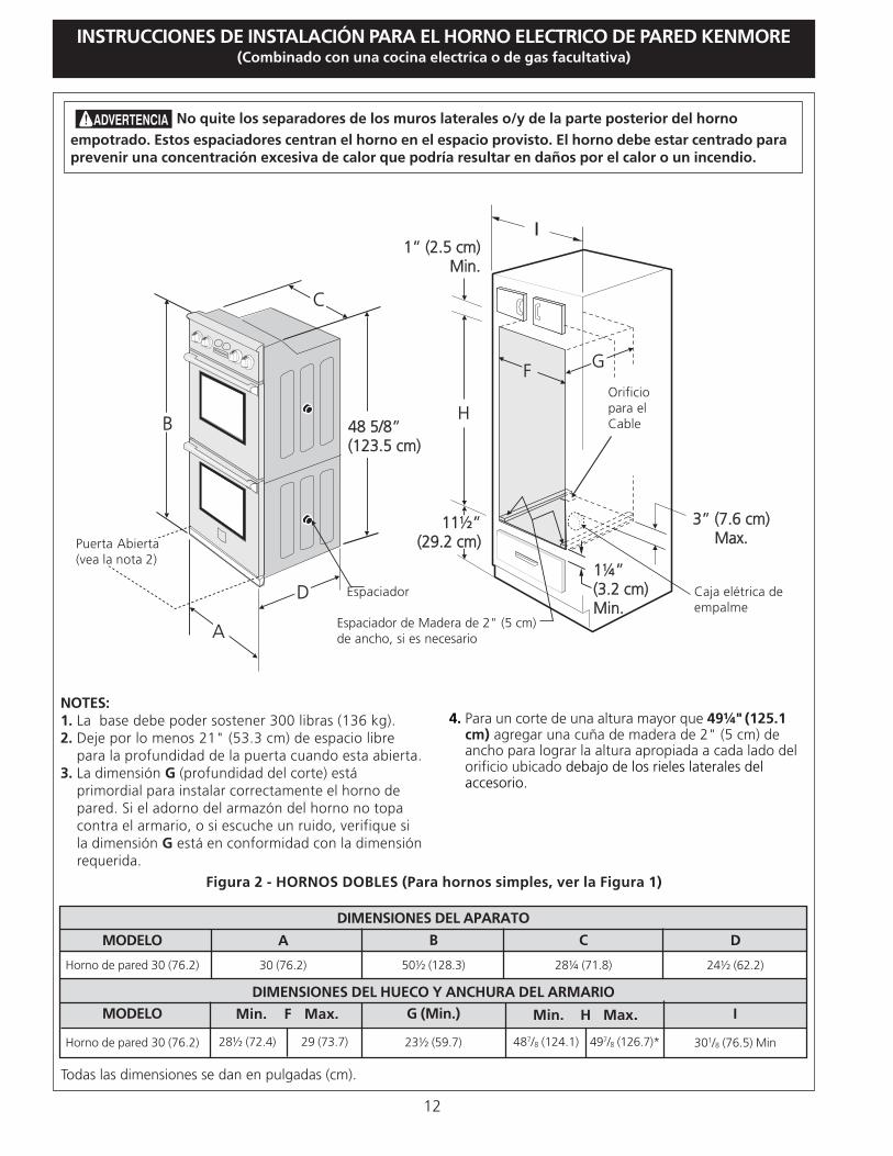
Figura 2 - HORNOS DOBLES (Para hornos simples, ver la Figura 1)
Todas las dimensiones se dan en pulgadas (cm).
NOTES:1. La base debe poder sostener 300 libras (136 kg).2. Deje por lo menos 21" (53.3 cm) de espacio libre
para la profundidad de la puerta cuando esta abierta.3. La dimensión G (profundidad del corte) está
primordial para instalar correctamente el horno depared. Si el adorno del armazón del horno no topacontra el armario, o si escuche un ruido, verifique sila dimensión G está en conformidad con la dimensiónrequerida.
4. Para un corte de una altura mayor que 49¼" (125.1cm) agregar una cuña de madera de 2" (5 cm) deancho para lograr la altura apropiada a cada lado delorificio ubicado debajo de los rieles laterales delaccesorio.
DIMENSIONES DEL APARATO
DIMENSIONES DEL HUECO Y ANCHURA DEL ARMARIO
Min. F Max. Min. H Max.
MODELO
Horno de pared 30 (76.2)
MODELO
Horno de pared 30 (76.2)
A
30 (76.2)
B
50½ (128.3)
G (Min.)
23½ (59.7)
C
28¼ (71.8)
D
24½ (62.2)
I
301/8 (76.5) Min28½ (72.4) 29 (73.7) 487/8 (124.1) 497/8 (126.7)*
No quite los separadores de los muros laterales o/y de la parte posterior del hornoempotrado. Estos espaciadores centran el horno en el espacio provisto. El horno debe estar centrado paraprevenir una concentración excesiva de calor que podría resultar en daños por el calor o un incendio.
F
I
H
G
11½”(29.2 cm)
11½”(29.2 cm)
1¼”(3.2 cm)Min.
1¼”(3.2 cm)Min.
3” (7.6 cm)Max.
3” (7.6 cm)Max.
1” (2.5 cm)Min.
1” (2.5 cm)Min.
B
A
D
C
48 5/8”(123.5 cm)48 5/8”(123.5 cm)
Puerta Abierta(vea la nota 2)
Espaciador Caja elétrica deempalme
Orificiopara elCable
Espaciador de Madera de 2" (5 cm)de ancho, si es necesario

13
INSTRUCCIONES DE INSTALACIÓN PARA EL HORNO ELECTRICO DE PARED KENMORE(Combinado con una cocina electrica o de gas facultativa)
Notas importantes para el instalador1. Lea todas las instrucciones contenidas en este manual
antes de instalar el horno.2. Saque todo el material usado en el embalaje del
compartimiento del horno antes de conectar elsuministro eléctrico o de gas a la estufa.
3. Observe todos los códigos y reglamentos pertinentes.4. Deje estas instrucciones con el consumidor.5. La puerta del horno se puede retirar para facilitar la
instalación.6. ESTE HORNO NO ESTÁ APROBADO PARA LA
INSTALACIÓN APILABLE O DE LADO A LADO.
Nota importante al consumidorConserve estas instrucciones y el manual del usuario parareferencia futura.
INSTRUCCIONESIMPORTANTES DE SEGURIDAD• Asegúrese de que su horno de pared sea instalado
y puesto a tierra de forma apropiada por uninstalador calificado o por un técnico de servicio.
• Este horno de pared debe ser eléctricamentepuesto a tierra de acuerdo con los códigos localeso, en su ausencia, con el Código Eléctrico NacionalANSI/NFPA No. 70–última edición en los EstadosUnidos, o el Código Eléctrico Canadiense CSAStandard C22.1, Part 1, en Canadá.
Pisar, apoyarse, o sentarse sobre lapuerta de este horno de pared puede causar seriaslesiones y daños al horno de pared.
• Nunca use su horno de pared para calentar unahabitación. El uso prolongado de la estufa sin laventilación adecuada puede ser peligroso.
La corriente eléctrica al horno debe
estar apagada mientras se hacen las conexiones delíneas. Si no se apaga, daños serios o la muertepodrían resultar.
1. CarpinteríaConsulte la Figura 1 o la figura 2 para conocer las dimen-siones pertinentes al modelo de su horno y al espacionecesario en el que poner el horno. La superficie donde seva a apoyar el horno debe de ser de maderacontrachapada sólida u otro material similar y, sobre todo,la superficie tiene que estar a nivel, de lado a lado, y deatrás hacia adelante.
2. Requerimientos EléctricosSe debe proveer el voltaje y la frecuencia apropiados a esteelectrodoméstico, y conectarse a un circuito individualcorrectamente puesto a tierra, protegido por un interruptor oun fusible. Para conocer el interruptor o fusible que requiriesu modelo, vea la placa serial para encontrar la consomacióndel vatiaje y refierase al cuadro A para encontrar el amperajedel interruptor o fusible.
Table A
Grados de Vatiosdel
electrodoméstico
240V
Menos de 4800W
4800W - 7200W
7200W - 9600W
9600W y +
Se recomiendauna protección
al circuito
20A
30A
40A
50A
Grados de Vatiosdel
electrodoméstico
208V
Menos de 4100W
4100W - 6200W
6200W - 8300W
8300W y +
Se recomiendauna protección
al circuito
20A
30A
40A
50A
Observe todos los códigos que gobiernan y ordenanzaslocales1. Un cable de 3 o 4 alambres monofásico 120/240 o 120/
208 voltios, 60 hertzios es la unica fuente eléctrica querequiere en un circuito separado en ambos lados de lalínea (alambre negro y alambre rojo) (se recomienda unfusible o un interruptor de retraso de tiempo). No funda acable neutro (alambre blanco). Se debe de tener precaucional combinar un horno de pared y una cubierta, refierase ala placa de seria de cada uno de los aparatos.
NOTA: Los tamaños y las conexiones del alambre debenconformarse con el tamaño del fusible y el grado de laaplicación de acuerdo con el código Eléctrico NacionalAmericano ANSI/NFPA No. 70- ultima edición, o con elestándar CSA canadiense C22.1 , código eléctricocanadiense, parte 1, y códigos y ordenanzas locales.
No se debera usar extensiones paraenchufar este electrodoméstico. Esto podría causarun incendio, choque eléctrico u otro tipo de dañopersonal. Si usted necesita un cable mas largo, puedeordernar un cable de 10" kit 903056-9010 llamando alcentro de Partes y Servicion Sears al 1-888-SU-HOGARSM.
2. Este electrodoméstico debe conectarse a la caja defusibles (o de cortacircuito), por medio de un cableblindado flexible o un cable con forro no metálico. Elcable blindado flexible que va desde el electrodomésticodebe de estar conectado directamente a la caja deempalme. La caja de empalme debe de estar localizadaen el lugar que se indica en la Figura 1 o 2, dejandotanto exceso de cable como sea posible entre la caja yel electrodoméstico, de forma que así el electrodomésti-co se pueda mover fácilmente, si fuera necesario parahacer una reparación.
3. Se debe de usar un conector que reduzca la tirantez deuna forma adecuada para unir el cable blindado flexiblea la caja de empalme.
14
INSTRUCCIONES DE INSTALACIÓN PARA EL HORNO ELECTRICO DE PARED KENMORE(Combinado con una cocina electrica o de gas facultativa)
En cuanto a las condiciones de despachoy almacenamiento en el invierno, asegúrese de que elhorno llegue a su destino final como mínimo tres (3)horas antes de encenderlo. Si se enciende el hornocuando aún está frío, se pueden dañar los controles.
3. Ajuste de la altura del hornoLa altura del horno se puede ajustar con cuñas de maderade 2" (5 cm) de ancho, donde sea necesario, para quequepa en un gabinete o abertura existente, cuando laaltura del corte es superior a 2713/16" (70,6 cm) en elcaso del horno único de pared o 49¼” (125.1 cm) en elcaso del horno doble de pared (ver la Figura 1 ó 2). Colocarlas cuñas de altura apropiada debajo de los rieles lateralesdel horno.
4. Conexión eléctricaEl usuario tiene la responsabilidad personal y obligaciónde utilizar un instalador calificado, para asegurar que lainstalación eléctrica está hacha de forma adecuada yestá conforme con el Código Eléctrico Nacional ANSI/NFPA No. 70-última edición en los Estados Unidos, o elCódigo Eléctrico Canadiense CSA Standard C22.1, Part1, en Canadá.
En este electrodomestico se necesita un cable detoma a tierra.
Este electrodoméstico viene equipado con un cable deconexión de cobre. Si esto tuviera que conectarse a loscables de aluminio de una casa, use solamente losconectores especiales aprobados para empalmes decobre y aluminio, de acuerdo con el Código EléctricoNacional y los reglamentos y códigos locales.
Este electrodoméstico se ha fabricado con un cable parael suministro de energía que tiene un alambre neutro decolor blanco y un alambre pelado de toma a tierraconectado al armazón.
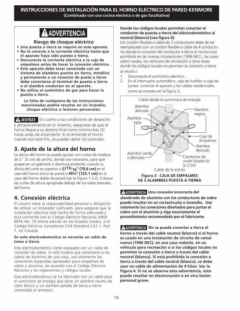
Donde los códigos locales permitan conectar elconductor de puesta a tierra del eléctrodoméstico alneutral (blanco) (vea figura 3):(Un cordón flexible o cable de 3 conductores debe de serreemplazado con un cordón flexible o cable de 4 conducto-res donde la conexión del conductor a tierra al neutro estaprohibida en las nuevas instalaciones (1996 NEC), las casassobre ruedas, los vehículos de recreación o otras áreasdonde los códigos locales no permiten la conexión a tierraal neutro.)1. Desconecte el suministro eléctrico.2. En el interruptor automático, caja de fusibles o caja de
juntas: conectar el aparato y los cables residencialescomo se muestra en la figura 3.
Una conexión incorrecta delalambrado de aluminio con los conductores de cobrepuede resultar en un cortacircuito o incendio. Usesolamente los conectores diseñados para juntar elcobre con el aluminio y siga exactamente elprocedimiento recomendado por el fabricante.
No se puede conectar a tierra elhorno a través del cable neutral (blanco) si el hornoes usado en una instalación de circuito de ramalnuevo (1996 NEC), en una casa rodante, en unvehículo para recreación o si los códigos locales nopermiten la conexión a tierra a través del cableneutral (blanco). Si está prohibida la conexión atierra a través del cable neutral (blanco), se debeusar un cable de alimentación de 4 hilos. Ver laFigura 4. Si no se observa esta advertencia, estopuede resultar en electrocución o en otra lesiónpersonal grave.
Riesgo de choque eléctrico• Una puesta a tierra se require en este aparato.• No lo conecte a la corriente eléctrica hasta que
el aparato haya sido puesto a tierra.• Desconecte la corriente eléctrica a la caja de
empalmes antes de hacer la conexión eléctrica.• Este aparato debe estar conectado con un
sistema de alambres puesto en tierra, metálicoy permanente o un conector de pueta a tierredebe conectarse al terminal de puesta a tierrao el alambre conductor en al aparato.
• No utilice el suministro de gas para hacer lapuesta a tierra.
La falta de cualquiera de las instruccionesmencionadas podría resultar en un incendio,
choque eléctrico o lesiones personales.
Figura 3 - CAJA DE EMPALMESDE 3 ALAMBRES PUESTA A TIERRA
Cable desde el suministro de energía
Cable de la estufa
Alambredesnudo
Alambrerojos
Caja deempalmes
Conductor deunión listado-UL(o CSA)
Alambre verdeo desnudo
Alambredesnudo
Alambrenegros

15
INSTRUCCIONES DE INSTALACIÓN PARA EL HORNO ELECTRICO DE PARED KENMORE(Combinado con una cocina electrica o de gas facultativa)
Si el horno se usa en una instalación de circuito deramal nuevo (1996 NEC), en una casa rodante, en unvehículo para recreación o si los códigos locales NOpermiten la conexión a tierra a través del cableneutral (blanco) (ver figura 4):
1. Desconecte el suministro eléctrico.2. En el interruptor automático, caja de fusibles o caja de
juntas: conectar el aparato y los cables residencialescomo se muestra en la figura 4.
5. Instalación del Gabinete El horno de pared puede inclinarse
cuando la puerta esta abierta. Los soportes demontaje que vienen con el horno de pared debende estar ajustadas al armario y al aparato paraevitar que el horno de pared se incline y ocasionequemaduras graves.
Instrucciones de instalación de los soportes demontaje1. Desembalar el horno de pared. Extraer la guarnición
inferior con cinta al panel lateral del horno. Buscar lasdos ménsulas antideslizables y los tornillos que seincluyen en el paquete de literatura.
2. Instale los soportes de montaje como en la figura 5. Nota:Para prevenir cualquier tipo de daño al cabinete esrecomendable perforar agujeros conn un diametro de1/16" (0,16cm) antes de instalar los soportes demontaje.
Peligro de Peso Pesado• Use 2 personas o más para mover e instalar el horno
de pared.• Si no cumple con esta instrucción, puede resultar
en lesiones pesonales o daños al horno de pared
NO conecte el alambre puesto a tierra a una tubería desuministro de gas. NO conecte el suministro de energíaeléctrica hasta que el electrodomestico haya sidopermanentemente puesto a tierra. Conecte el alambre depuesto a tierra antes de enchufar por primera vez elelectrodomestico.
Si está conectado a un sistemaeléctrico de 4 alambres, el armazón delelectrodoméstico NO TIENE QUE estar conectado alalambre neutro del sistema eléctrico de 4 alambres.
NOTA AL ELECTRICISTA: Los conductores de cableblindados provistos con este artefacto son aprobados porUL para la conexión al alambrado de casa de un calibremayor. El aislamiento de los conductores está calificadopara temperaturas más altas que las del alambrado dela casa. La capacidad de corriente del conductor estágobernada por la calificación de la temperatura delaislamiento alrededor del alambre en vez de solamenteel calibre del alambre.
Figura 4- CAJA DE EMPALMESDE 4 ALAMBRES PUESTA A TIERRA
Alambredesnudo
Cable desde el suministro de energía
Alambreverde odesnudo
Cable de la estufa
Caja deempalmes
Conductor de uniónlistado-UL (o CSA)
Alambre blancoAlambre
rojos
Alambre blanco
Alambrenegros
Figura 5
Soportes demontaje
43 5/8" *(110.8 cm)
Hvea figure 2
F vea figura 2
Horno de pared doble
Soportes demontaje
22 3/16" *(56.4 cm)
Hvea figura 1
F vea figura 1
Horno de pared simple
* Si hay instaladas cuñas de madera, calcular estadimensión desde la parte superior de la cuña hasta elmedio del soporte de montaje.

16
INSTRUCCIONES DE INSTALACIÓN PARA EL HORNO ELECTRICO DE PARED KENMORE(Combinado con una cocina electrica o de gas facultativa)
IMPORTANTENo levante el horno por la manija de la puerta.
3.Insertar el horno en la abertura del gabinete. Deslizar elhorno hacia dentro dejando 1½” (3,8 cm) de espaciolibre entre el horno y la parte delantera del gabinete (verla Figura 6). Empujar el cable blindado a través delorificio del gabinete y hacia la caja de paso mientras sedesliza el accesorio hacia adentro.
4.Empujar el horno hacia adentro y en contra del gabinete;la ménsula lateral del horno enganchará en los soportesde montaje instalados en el lado del gabinete.
Para extraer el horno en caso de reparación, usar las dosherramientas provistas con el horno. Insertar unaherramienta en el orificio a cada costado del marco delhorno. Los orificios se pueden ver cuando la puerta estáabierta. Después de insertar las herramientas, extraer elhorno hacia fuera (ver la Figura 7).
5. Instalación de la moldutra inferior: Fije la moldura inferior usando los 2 tornillos provistos en
los agujeros de montaje localizados en cada moldura lateraldebajo del marco del horno (véase el cuadro 8). Es preferibleusar un destornillador largo para alcanzar los agujeros dela moldura lateral debajo de la puerta. Si es necesario,usted puede también quitar la puerta del horno (véase lasección apropiada en su guía de cuidado) para ayudarle afijar la moldura inferior.
Figura 6
1 1/2" (3.8 cm)distancía entre launidad y el gabinete
Figura 8
GuarniciónInferior
Tornillosprovistos
Figura 7
1 2 3
HornoCabinete
Soporte demontaje
instalado en elgabinete
Lateralderecho
herramientaincluida
soporte demontajeliberado
Horno retiradodel gabinete
Introduzca laherramienta que traeel electrodoméstico enel hoyo.
Bracketdel
horno
17
INSTRUCCIONES DE INSTALACIÓN PARA EL HORNO ELECTRICO DE PARED KENMORE(Combinado con una cocina electrica o de gas facultativa)
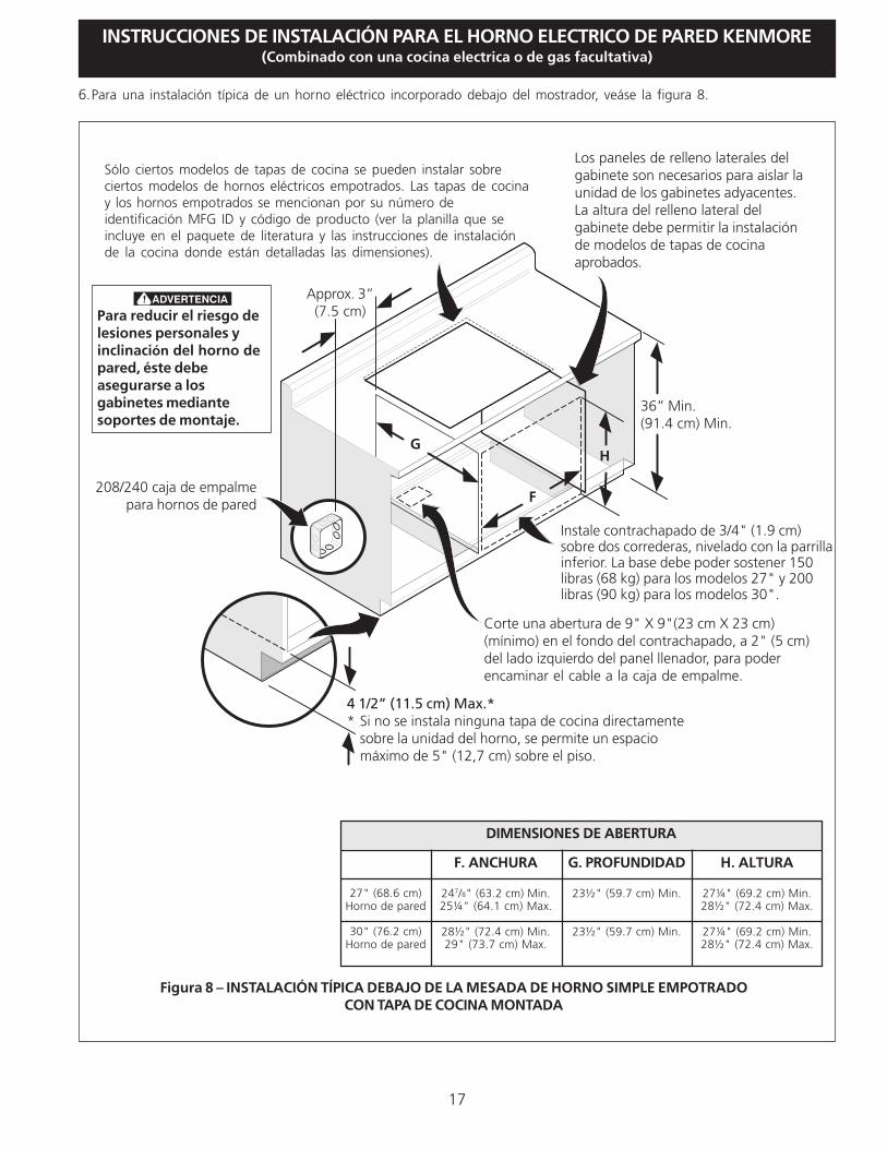
Sólo ciertos modelos de tapas de cocina se pueden instalar sobreciertos modelos de hornos eléctricos empotrados. Las tapas de cocinay los hornos empotrados se mencionan por su número deidentificación MFG ID y código de producto (ver la planilla que seincluye en el paquete de literatura y las instrucciones de instalaciónde la cocina donde están detalladas las dimensiones).
G
F
H
36” Min.(91.4 cm) Min.
Figura 8 – INSTALACIÓN TÍPICA DEBAJO DE LA MESADA DE HORNO SIMPLE EMPOTRADOCON TAPA DE COCINA MONTADA
Approx. 3”(7.5 cm)Para reducir el riesgo de
lesiones personales yinclinación del horno depared, éste debeasegurarse a losgabinetes mediantesoportes de montaje.
4 1/2” (11.5 cm) Max.** Si no se instala ninguna tapa de cocina directamente
sobre la unidad del horno, se permite un espaciomáximo de 5" (12,7 cm) sobre el piso.
Instale contrachapado de 3/4" (1.9 cm)sobre dos correderas, nivelado con la parrillainferior. La base debe poder sostener 150libras (68 kg) para los modelos 27" y 200libras (90 kg) para los modelos 30".
Corte una abertura de 9" X 9"(23 cm X 23 cm)(mínimo) en el fondo del contrachapado, a 2" (5 cm)del lado izquierdo del panel llenador, para poderencaminar el cable a la caja de empalme.
208/240 caja de empalmepara hornos de pared
Los paneles de relleno laterales delgabinete son necesarios para aislar launidad de los gabinetes adyacentes.La altura del relleno lateral delgabinete debe permitir la instalaciónde modelos de tapas de cocinaaprobados.
27" (68.6 cm)Horno de pared
30" (76.2 cm)Horno de pared
DIMENSIONES DE ABERTURA
F. ANCHURA
247/8" (63.2 cm) Min.25¼" (64.1 cm) Max.
28½" (72.4 cm) Min.29" (73.7 cm) Max.
G. PROFUNDIDAD
23½" (59.7 cm) Min.
23½" (59.7 cm) Min.
H. ALTURA
27¼" (69.2 cm) Min.28½" (72.4 cm) Max.
27¼" (69.2 cm) Min.28½" (72.4 cm) Max.
6.Para una instalación típica de un horno eléctrico incorporado debajo del mostrador, veáse la figura 8.

18
INSTRUCCIONES DE INSTALACIÓN PARA EL HORNO ELECTRICO DE PARED KENMORE(Combinado con una cocina electrica o de gas facultativa)
Figura 9 - INSTALACION TÍPICA PARA UNA ESTUFA DE GAS ENCIMADE UN HORNO DE PARED INSTALADO DEBAJO DEL MOSTRADOR
18”(45.7 cm) Max.
6 1/2” Min.(16.5 cm)
Adaptorde gas
4”(10 cm)
Tomacorrientepuesto a tierrade 120Voltios /
60Hz
Regulador depresión
Conector flexible paraartefactos
Lados delgabinete o panel
llenador
Gabinete del hornode pared
5” Max.(12.7 cm)
Adaptorde gas
ESTUFA DE GAS
Válvula de cierre manual(para tener acceso a la válvula
de cierre manual)
19
INSTRUCCIONES DE INSTALACIÓN PARA EL HORNO ELECTRICO DE PARED KENMORE(Combinado con una cocina electrica o de gas facultativa)
IMPORTANTEUn ventilador ubicado dentro de la partetrasera superior arriba del horno (enalgunos modelos) permite la refrigeraciónde los componentes eléctricos yelectrónicos de enfriamiento. Si el hornoha estado funcionando a altastemperaturas, el ventilador seguiráfuncionando después de apagar el horno.
En el horno doble de pared, ambosventiladores pueden estar ENCENDIDOScuando uno de los hornos se utiliza en modolimpieza. Esto es normal. Esto proporcionarauna temperatura fresca a los componentesde su electrodoméstico.
7. Verificación del funcionamientoSu modelo está equipado con un Control Electrónico deHorno. Cada una de las funciones ha sido controlada enfábrica antes del despacho. Sin embargo, le sugerimosverificar el funcionamiento de los controles electrónicosuna vez más. Consulte la Guía de Uso y Cuidado paraver el funcionamiento del horno.
1. Extraer todos los elementos de la parte interior delhorno.
2. Encender el horno (Consular la Guía de Uso y Cuidado.)
3. Verificar el funcionamiento de los controles electrónicosdel horno:Hornear – Verificar que esta función caliente el horno.Veinte minutos después de encender el horno, abrir lapuerta y ver si se siente que el calor emana desde suinterior.
Asar– Cuando se pone el horno para asar, elelemento de arriba del horno debe de ponerse rojo.
Convección (algunos modelos) – Cuando se configurael horno para horneado o asado por convección y seenciende el ventilador. El ventilador de conveccióndejará de funcionar cuando se abre la puerta del hornodurante el horneado o asado por convección.
Ubicación del número de modelo y de serieLa placa con el número de serie está ubicada en laguarnición interior lateral del horno y se puede ver cuandose abre la puerta.
Cuando haga pedidos de repuestos o solicite informacióncon respecto a su horno, esté siempre seguro de incluirel número de modelo y de serie y el número o letra dellote de la placa de serie de su horno.
Antes de llamar al servicioLea la sección Lista de Antes de llamar en su Manual delUsuario. Esto le podrá ahorrar tiempo y gastos. Estalista incluye ocurrencias comunes que no son el resultadode defectos de materiales o fabricación de esteartefacto.
Lea la garantía y la información sobre el servicio en suManual del Usuario para obtener el número deteléfono gratuito y la dirección del servicio o llama1-888-SU-HOGARSM.
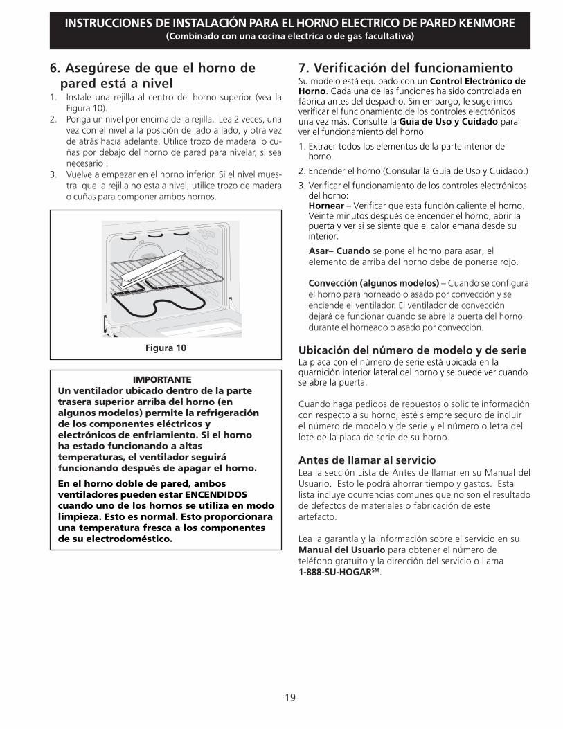
6. Asegúrese de que el horno depared está a nivel
1. Instale una rejilla al centro del horno superior (vea laFigura 10).
2. Ponga un nivel por encima de la rejilla. Lea 2 veces, unavez con el nivel a la posición de lado a lado, y otra vezde atrás hacia adelante. Utilice trozo de madera o cu-ñas por debajo del horno de pared para nivelar, si seanecesario .
3. Vuelve a empezar en el horno inferior. Si el nivel mues-tra que la rejilla no esta a nivel, utilice trozo de maderao cuñas para componer ambos hornos.
Figura 10

20
INSTRUCCIONES DE INSTALACIÓN PARA EL HORNO ELECTRICO DE PARED KENMORE(Combinado con una cocina electrica o de gas facultativa)
Notas

![APPLICATION MUST BE TYPED ALL FIELDS MUST …term:name]/[node...APPLICATION MUST BE TYPED (Editable Form) ALL FIELDS MUST BE COMPLETED, UNLESS LISTED AS OPTIONAL First Name: John Middle](https://static.fdocuments.in/doc/165x107/5ad068457f8b9ad24f8d9eea/application-must-be-typed-all-fields-must-termnamenodeapplication-must.jpg)