INSTALLATION AND SERVICE MANUAL FOR CHAIN … and service manual for chain conveyors, belt conveyors...
32
INSTALLATION AND SERVICE MANUAL FOR CHAIN CONVEYORS, BELT CONVEYORS AND GRIPPER ELEVATORS / LOWERATORS
-
Upload
nguyendang -
Category
Documents
-
view
229 -
download
1
Transcript of INSTALLATION AND SERVICE MANUAL FOR CHAIN … and service manual for chain conveyors, belt conveyors...

INSTALLATION AND SERVICE MANUAL FOR CHAIN CONVEYORS, BELT CONVEYORS AND
GRIPPER ELEVATORS / LOWERATORS

NERCON PROPRIETARY STATEMENT The following information is proprietary information of NERCON and must not be used except in connection with our work, or in any manner disclosed to any third party without the prior written consent of NERCON. All rights of design and invention are reserved.
Recipient of this manual acknowledges that he will abide by the instructions contained in this manual and in the training classes furnished by NERCON. He will not tolerate any operation that is contrary to these instructions. If the recipient observes equipment that presents a hazard, he will promptly inform NERCON so that a solution can be achieved.

Table of Contents Section 1: Introduction
How to Use This Manual .................................................................................................................................... 1-1 Equipment Warranty ........................................................................................................................................... 1-2
Section 2: Safety
General................................................................................................................................................................. 2-1
Conveyor Safety Rules......................................................................................................................... 2-1a Mechanical Maintenance Safety .......................................................................................................... 2-1b Electrical Maintenance Safety.............................................................................................................. 2-1c Safety Guidelines ................................................................................................................................. 2-1d Application Safety ................................................................................................................................ 2-1e Backstop Devices ................................................................................................................................. 2-1f Power Gates and Switches ................................................................................................................... 2-1g Headroom ............................................................................................................................................. 2-1h Guarding ............................................................................................................................................... 2-1i
Controls Safety ..................................................................................................................................................... 2-2 Electrical Code ..................................................................................................................................... 2-2a Control Stations .................................................................................................................................... 2-2b Safety Devices ...................................................................................................................................... 2-2c Emergency Stops and Restarts ............................................................................................................. 2-2d
Transfer, Loading and Discharge Points............................................................................................................. 2-3
Section 3: Installation
General Installation Instructions ......................................................................................................................... 3-1 Installation & Maintenance of Tabletop and Belt Conveyors ............................................................................ 3-2 Belt Tensioning &Tracking................................................................................................................................. 3-3
Section 4: Preventive Maintenance Guide
Introduction ......................................................................................................................................................... 4-1 Preventive Maintenance Schedule ...................................................................................................................... 4-2
Purpose ................................................................................................................................................. 4-2a Drive Chain Lubrication...................................................................................................................................... 4-3
Lubrication Table "C" .......................................................................................................................... 4-3 Lubrication Types and Methods ......................................................................................................................... 4-4 Lubrication Types and Methods Table ............................................................................................................... 4-5
Slow Speed Conveyor Drive Chains (Motor Gearbox to Head Shaft) ............................................... 4-5a Wear...................................................................................................................................................... 4-5b Double Pitch Chain .............................................................................................................................. 4-5c Conveyor Chains .................................................................................................................................. 4-5d Sprockets .............................................................................................................................................. 4-5e
Lubrication and Care of Sealed Ball Bearings ................................................................................................... 4-6 Conditions Table .................................................................................................................................. 4-6a
Tabletop Chain Lubrication ................................................................................................................................ 4-7 Periodic Inspection .............................................................................................................................................. 4-8
Tabletop Conveyor Checklist............................................................................................................... 4-8a Repair and Replacement ...................................................................................................................... 4-8b Belt Conveyor Checklist ...................................................................................................................... 4-8c

Section 4: Preventive Maintenance Guide (Continued) Cleaning ............................................................................................................................................................... 4-9
Chain Conveyor………………………………………………………………………………….4-9a Belt Conveyor……………………………………………………………………………………4-9b
Section 5: Troubleshooting
Troubleshooting Guide........................................................................................................................................ 5-1
Tabletop Chain Conveyor .................................................................................................................... 5-1a Belt Conveyor....................................................................................................................................... 5-1b Components .......................................................................................................................................... 5-1c Electrical System .................................................................................................................................. 5-1d Motor Control Panel ............................................................................................................................. 5-1e Safety Interlocks ................................................................................................................................... 5-1f Photo Electric Cells .............................................................................................................................. 5-1g Limit Switches...................................................................................................................................... 5-1h Relays ................................................................................................................................................... 5-1i Pneumatic Systems............................................................................................................................... 5-1j
Mechanical Assemblies and Equipment…………………………………………………………..5-1k
Section 6: General Maintenance Guidelines
Worm Gear Reducers……………………………………………………………………………………....6-1 Spiral Bevel Gearbox (Right Angle)……………………………………………………………………….6-2 Shaft Mount Reducers……………………………………………….………………………...…………..6-3 Synchronous Belt Drives…………………………………………….………………………...…………..6-4 V-Belt System………………………………………………………….……………………...…………..6-5 Timing Belt Drives…………………………………………………….……………………..……….…...6-6 Bearings……………………………………………………………………………………..……….……6-7 Electric Motors……………………………………………………….……………………..…….……….6-8
Variable Frequency Drives……………………………………..…………………………..………….…...6-9 .
Section 7: Gripper Elevator and Lowerator
Container Grip Setting…………………………………………………………………………………......7-1 Line Control……………………………….……………………………………………………………….7-2 Lubrication……………………………………………..………………………………………………......7-3 Mechanical Adjustments………………….…………………………………………………….………….7-4 Cleaning……………………………………………….…………………….……………….…………….7-5
Section: 1 - Introduction
1-1: How to Use this Manual
This manual is supplied to assist you in installing, maintaining and servicing NERCON equipment. It is essential for safe and efficient system operation that the information and guidelines presented here are properly understood and implemented. Following is a brief description of the information contained in each section:
This manual is intended for personnel who will install, maintain, repair, clean, clear and otherwise operate the supplied product handling equipment. The Maintenance Manual provides maintenance personnel with the information necessary to maintain the system effectively. The manual provides the definition of the primary equipment, the roles and responsibilities of maintenance personnel, and the regular activities essential to the support and maintenance of the equipment. This manual shall be used in conjunction with the equipment support drawings and other 3rd-party vendor documentation. It is expected that the operators and maintenance personnel are skilled in the operation and maintenance of electrical and mechanical equipment used in the packaged food and consumer goods industry. 1.Introduction: Basic information about the manual and the system and trademarks/servicemarks (if any) used in the manual.
2. Safety: Safety precautions for conveyor maintenance. 3. Installation: Mechanical and Electrical information about the Installation of the various types of equipment in the conveyor system. 4. Preventive Maintenance and Inspection Guide: One of the most important factors in the overall cost effectiveness of your material handling system is that of preventive maintenance and periodic inspection; that is, eliminating the cause of potential trouble before the trouble occurs. This concept makes it possible to perform maintenance and repair operations on a predetermined schedule rather than according to chance. Implementing an effective preventive maintenance program on your NERCON equipment serves to increase its dependability, longevity, and efficiency, all of which add up to lower operating costs. Section 4 contains preventive maintenance and periodic inspection information for conveyor mechanical equipment. Observe the equipment when it is functioning properly in order to detect failure and/or to perform maintenance or adjustment on the equipment. 5. Troubleshooting: Despite the best operating techniques and preventive maintenance program, machines sometimes do fail. This section contains suggested step- by-step methods to aid in detecting the cause or causes of these failures.

1-2: Equipment Warranty A. NERCON warrants the items supplied by NERCON will conform to the Agreement, shall be
suitable for the intended use, and shall be free of defects in material and workmanship at the time of acceptance of the work for a period of (12) months.
B. THERE ARE NO WARRANTIES, EXCEPT OF TITLE, EXPRESSED OR IMPLIED,
INCLUDING WARRANTIES OF MERCHANTABILITY OR FITNESS FOR ANY PURPOSE EXCEPT AS EXPRESSLY SET FORTH IN THIS ARTICLE.
C. NERCON liability for breach or warranty or otherwise is limited to the following actions:
1. Structural members: Defective or non-conforming structural members will be
repaired or replaced by NERCON at PURCHASER'S site.
2. Items of NERCON design or manufacture: Defective components will be repaired or replaced when same are returned to NERCON, FOB NERCON'S plant.
3. Items not of NERCON'S design or manufacture: NERCON’S liability for defects in
material or workmanship for computer hardware, peripherals, software developed by third parties or other items not designed or manufactured by NERCON, which are incorporated into the System, shall be limited to that of the vendor thereof.
4. NERCON-developed controls: NERCON liability for defects are limited to the
correction of demonstrable defects that are defined and documented by the PURCHASER.
D. NERCON shall be relieved of any obligations under the foregoing warranty as to any items
which: (1) Have not been properly maintained or are not maintained to the current support level in accordance with NERCON'S and manufacturer's recommended procedures and written instructions; (2) Have not been operated in accordance with NERCON'S or manufacturer's recommended procedures and written instructions; (3) Have been modified by persons other than NERCON (except where prior approval has been granted by NERCON); (4) Differ from the operating conditions and methods contemplated by the Agreement.
E. NERCON shall be given access to make warranty repairs.
F. PURCHASER shall notify NERCON in writing of all warranty claims, defining the nature,
extent and effect of the defect.

Section: 2 - Safety 2-1: General Safety Rules
Note: The safety procedures/policies listed in this chapter are not intended to address fire- related considerations. Your system must comply with any applicable national, state, and local codes. Follow safety precautions for industrial work at all times. The information in this chapter includes guidelines specified in the latest issue of the American National Standard Institute (ANSI) booklet entitled Safety Standards for Conveyors and Related Equipment B20.1-19--. We have included additional precautions that are to be observed in accordance with any ANSI regulations that are applicable. With any piece of industrial equipment, conditions exist that might cause injury to you or your co-workers. Because it is not possible to describe each potentially hazardous situation that might develop, you must be alert at all times for unsafe conditions. To avoid injury, use maximum possible care and common sense and adhere to all safety standards. Until you are appropriately trained, you are not authorized to operate, install, maintain, or modify the system. See your supervisor about receiving this training or authorization before your operate, install, maintain, or modify the material handling system. Take special care while maintaining and inspecting electrical equipment and devices. All personnel working on or around the system should be aware of, and adhere to, all CAUTION, DANGER, and WARNING signs. These signs are posted to reduce the risk of injury to all personnel. Maintain signs in a legible condition. Contact your supervisor to post additional safety signs if you feel they are necessary.
Follow these conveyor safety rules, as well as specific regulations and guidelines listed in this publication: 2-1a: Conveyor Safety Rules
! Do not touch moving conveyor parts. ! Do not walk, ride or climb on the
conveyor. ! Do not operate the conveyor with chain
guards or other protective guards removed. ! Keep jewelry, clothing, hair, etc., away
from the conveyor. ! Know the location and function of all
start/stop devices and keep those devices free from obstruction.
! Clear all personnel from the equipment
before starting the conveyor. ! Do not attempt to clear product jams while
the conveyor is running. ! Allow only trained and authorized
personnel to maintain or repair conveyor equipment.
! Do not load the conveyor beyond specified
design limits. ! Do not attempt to make repairs to the
conveyor while it is running. ! Do not modify equipment without
checking with the manufacturer. ! Do not operate or perform
maintenance on equipment when taking any type of drug, sedative, when under the influence of alcohol, or when over fatigued.
When a conveyor is stopped for maintenance or repair purposes, you must lock out or tag out the starting devices, prime movers, or powered accessories in accordance with a formalized procedure designed to protect everyone involved with the conveyor against an unexpected restart. Also, alert all personnel to the hazard of stored energy, which can exist after the power source is locked out. For additional information, refer to the latest issue of ANSI Z244.1-19--, American National Standard for Personnel Protection - Lockout/Tagout of Energy Sources - Minimum Safety Requirements. Also, OSHA 29CRF Part 1910.147 "Control of Hazardous Energy sources (Lockout/Tagout)", which includes requirements for release of stored energy. 2-1b: Mechanical Maintenance Safety
Lubricate conveyors when they are not in motion wherever practical. Only trained personnel who are aware of the hazard of the conveyor in motion should be permitted to lubricate a conveyor that is operating.
After you lubricate the conveyor, check to make sure that none of the lubricants or other process liquids have spilled or dropped onto the floor. These liquids create a hazardous condition. If you notice a drip, install a drip pan or other means of eliminating the hazard.
2-1c: Electrical Maintenance Safety
When an equipment problem occurs, the first priority is to ensure that power is disconnected from the affected area, as well as from the control panel where troubleshooting and repairs are performed.
Once you verify that power is locked out, make sure you inform other personnel in the area of the situation so they do not unexpectedly restore power.
After you inform your co-workers, recheck the power supply to ensure that power is disconnected in the affected control panel. Remove fuses only with insulated fuse pullers and check terminal strips for current-carrying wires. Before you perform any repairs with an exposed conductor or terminal, use an exposed conductor or terminal; use an approved voltmeter to check for continuity to ground and continuity between other current- carrying conductors. When you perform any kind of maintenance or repair involving electrical components, follow the guidelines listed below: 2-1d: Safety Guidelines
! NEVER reset a circuit breaker or replace an open fuse before determining and correcting the cause of the circuit interruption.
! NEVER bypass or use a jumper to
replace any limit switch, fuse, circuit breaker, or other circuit protection or safety device.
! NEVER replace an open fuse with
another that is not rated at the proper current and voltage. Always double- check correct fuse specifications rather than replace the open fuse with one of the same current and voltage rating.
! NEVER rest tools on motors,
transformers, terminal strips, or other control panel or electrical components. All tools used should be kept in a toolbox or pouch.

! NEVER restore power or restart equipment before verifying that all tools, spare parts, etc., are removed from the work area and are safely stored.
! NEVER restore power or restart
equipment before verifying that ALL personnel are aware of the condition and are safely clear of the equipment.
! ALWAYS replace and safety
devices and guards removed during maintenance or repair before you restore power or restart equipment.
! ALWAYS use extreme caution and
follow recommended safety procedures while you perform any electrical inspection or maintenance operations.
2-1e: Application Safety
The equipment used in your system is designed to convey specified commodities or materials within a certain rate and speed. It might not be possible to safely use the equipment outside of the intended capacities or speeds. Check with your supervisor if you have questions regarding the safe operation of the equipment.
2-1f: Backstop Devices
Provide antirunaway, brake, or backstop devices on all incline, decline, or vertical conveyors with which the effect of gravity might allow uncontrolled lowering of load if that lowering would cause injury to you or co- workers.
2-1g: Power Gates and Switches Where and if specified, NERCON has provided power-positioned gate and switch sections with devices that prevent these sections from falling in the event of power failure. NERCON has also provided a means of preventing conveyed material from discharging into an open area created by the lifting of the gate or switch.
2-1h: Headroom When equipment is installed above exit passageways, aisles, or corridors, provide a minimum clearance of 6 feet 8 inches (measured vertically from the floor or walking surface to the lowest part of the conveyor or guards). Where providing the minimum clearance of 6 feet 8 inches through an emergency exit will impair system function, provide alternate passageways. It is permissible; however, to allow passage under conveyors with less than 6 feet 8 inches clearance from the floor for other than emergency exits if a suitable warning indicates low headroom. 2-1i: Guarding If necessary to protect personnel from hazards, guard by location or position all exposed moving machinery parts that present a hazard to personnel at their workstations. When a conveyor passes over a walkway, roadway, or work station, it is considered to be guarded solely by location or position if all moving parts are at least 8 feet above the floor or walking surface, or are otherwise located so the personnel cannot inadvertently come in contact with hazardous moving parts.

2-2: Controls Safety 2-2a: Electrical Code
All electrical installations and wiring must conform to the National Electrical Code (Article 670 and other applicable articles) published by the National Fire Protection Association and approved by the American National Standards Institute, Inc.
2-2b: Control Stations
Arrange control stations so that equipment operation is visible from the stations and clearly mark or label each station to indicate its function.
The emergency stop devices installed with your system are designed so that they cannot be overridden from other locations.
Keep the area around your control station clear. Remove all miscellaneous equipment (such as inactive and unused actuators, controllers, and wiring) from control stations and panel boards, as well as obsolete diagrams, indicators, control labels, and other material that might confuse the operator.
2-2c: Safety Devices
All safety devices, including wiring of electrical safety devices, operate in a "fail- safe" manner; that is, if power or the device fails, a hazardous condition will not result.
2-2d: Emergency Stops and Restarts
In case of an emergency stop, first determine the cause of the stoppage and correct the situation that warranted the stop. To resume operation after a stoppage, manually reset or start at the location where the emergency stop occurred.
Note: Before you try to correct the situation, lock out or tag out the starting device, unless it must be operated to determine the cause or to safely remove the stoppage. For additional information, refer to the latest issue of ANSI Z244.1-19--, American National Standard for Personnel Protection Lockout/Tagout of Energy Sources - Minimum Safety Requirements. 2-3: Transfer, Loading, and Discharge Points Prevent free-falling material that might result from flooding, ricocheting, or uncontrolled free-fall from occurring. At transfer, loading, and discharge points, prevent unconfined and uncontrolled free-fall of material resulting from flooding, ricocheting, overloading, trajectory, leakage, or a combination thereof, if the material would create a hazard to personnel.
Warning Failure to follow these rules can
result in injury. Note: The safety standards outlined in this section have NOT been exactly duplicated from the latest issue of the ANSI booklet, Safety Standards for Conveyors and Related Equipment B20.1-19--. We recommend that all operators and maintenance personnel review this booklet, which you can obtain by contacting the American Society of Mechanical Engineers at the following address:
American Society of Mechanical Engineers United Engineering Center
345 East 47th Street New York, NY 10017

Section 3: Installation
3-1: General Installation Instructions
Note: All equipment must be installed to conform to the National and Local Safety Codes. In the event that any caution or warning labels affixed to the equipment are damaged in shipping or obscured from vision because of the position of the equipment on site, you should order the appropriate replacement labels before operating the equipment.
1. All components of the system are
numbered for assembly. Proper assembly is accomplished by merely matching the numbers. The numbers are marked on the conveyor sections and also on the conveyor assembly drawings.
2. Having laid out the conveyor to match
the assembly numbers, connect all joints, carefully check conveyor for correct elevation and level, then tighten the fasteners to secure the section being installed.
3. As the system is assembled, check all
fasteners to insure that they are secure, even those that are not connected with the assembly of the sections.
4. Check the conveyor for flatness and
obstruction with special attention given to splice joints.
4.5. Check all guide rails for smoothness at
joints, curves, and splices.
5. Check motor alignment and alignment of drive sprockets to be sure there are no loose set-screws.
6. Check the rotation of the motor/reducer
driveshaft to assure that it will provide the proper direction of travel for the chain/belt.
7. Any gearboxes on the system will have
been filled with oil prior to testing and shipping the conveyor. Check each gearbox to insure correct oil level.
8. All bearings have been greased prior to
testing and shipping the conveyor and should not require further lubrication at this time unless conveyor has been stored for a long period. In the event that the system has been exposed to abrasive construction materials (cement, sand, brick dust, etc.), the system should be cleaned and all abrasive debris removed before starting the system.
9. When installing the carrying roller
chains, extreme attention should be paid to attaining the correct catenary "sag" at the drive end. The chain(s) should just touch the bottom of the return roller in the optimum situation. Weekly inspections of catenary “sag” at all drive ends are recommended. When catenary "sag" reaches a distance of 3-1/2" from centerline of roller axle to bottom of carrying chain(s), a link should be removed.

3-2: Installation & Maintenance of Tabletop and Belt Conveyors Proper care and maintenance of tabletop chains will provide smooth, efficient operation, and extended chain and conveyor life. It is, therefore, necessary to consider the factors that influence a “good” maintenance program. Namely:
1. Proper Installation 2. Good Lubrication 3. Cleanliness 4. Periodic Inspection 5. Repair and Replacement of worn
components
Installation:
1. Table Top Conveyor
! Check conveyor for flatness and obstructions with special attention given to splice points.
! Pull a short (about 3 feet) section of chain through the entire conveyor to detect any obstruction, or areas of tight clearance. Make sure chains have plenty of clearance, especially on the inside of curves.
! Remove obstructions and adjust wearstrips to provide proper chain clearance.
Chain Installation:
! Install the chain. Caution: Thread chainonto conveyor carefully to avoid twisting and possible damage to the chain. Make sure all chains are facing in the correct direction for travel, as indicated on the bottom or side of the chain.
2. Belt Conveyor
! Check conveyor for flatness and
obstructions with special attention given to splice points.
! Each section must be horizontal across its width to prevent gravity caused drifting of the belt to the low side.
! As a preliminary adjustment, all pulleys,
snub rollers, carrying idlers and return idlers must be square to the frame and parallel to each other. Final adjustment requires this squaring to be done with the belt centerline as a reference.
Belt Installation:
! Once the roll of belting is at the point of
installation, it should be placed on a shaft for unrolling and threading onto the conveyor. If this is not possible, the belt may need to be unrolled and place in loops to be pulled onto the conveyor. These loops need to be large so as to prevent kinking or creasing the belt. At no time should any weight be placed on the folded portion of the belt.
! In pulling the belt onto the conveyor and threading it through the pulleys, be sure the pulling force is evenly distributed across the width of the belt to prevent an damage to the belt.
! Be sure to follow the correct belt path as indicated on the equipment drawing.
! If the belt did not come spliced from the factory, you will need to cut the belt to the proper length, making sure the ends are
! cut square to the centerline of the belt. Belt take-up is determined after the take- up is adjusted to within 1” of the position of minimum travel.
! Use the lacing provided with the belt or, if none was provided, one of the proper size and type as recommended by the belt manufacturer, and follow the fastener manufacturer’s instructions carefully.
! If the belt is to be made endless by gluing or vulcanizing, be sure the proper type of splice (finger, step, skived, etc.) and proper type of splice kit or glue is used as recommended by the belt manufacturer.

3-3: Belt Tensioning & Tracking
! Tension must be sufficient to prevent slippage between the drive pulley and the belt; and for the belt to conform to the crown of any crowned pulley.
! To check the tension, (with the belt stopped) press down on the belt at the outside edge of the belt where it contacts a crowned pulley. If there is a play between the belt and the pulley the tension needs
! to be increased. This should result in the proper tension. If the slippage occurs at the drive pulley, further tensioning is required. DO NOT OVER TENSION THE BELT. This will cause excessive stretch of the belt and may damage the belt, pulleys and shafts. It also makes the belt more difficult to track and requires more horsepower to move the belt.
Tracking:
! If the belt moves out of line too quickly to
make tracking adjustments, re-check the conveyor installation to be sure the bed is properly aligned and that all pulleys and rollers are square to the belt centerline.
! Be sure the belt has been spliced squarely, and re-splice if necessary. If these adjustments do not correct the belt tracking sufficiently to proceed with the following adjustments, consult the factory.
! With the belt empty, start with the
return run working toward the tail pulley and then follow with the top run in direction of the belt travel. Re-check the tracking with a fully loaded belt only after the empty belt has been properly tracked.
! Tracking adjustments are to be
made while the belt is running.
! After locating a trouble spot, adjustments should be made over some length of conveyor preceding the are of trouble.
! When making adjustments let the belt make at least three complete revolutions after each adjustment to determine the effect on the belt tracking (unless it appears the belt will run off a pulley or conveyor frame).
! If the adjustment has caused the belt to over correct, reposition the same roller or pulley that caused the over correction-do not try to compensate by making an adjustment in a different area.
! When adjusting rollers and pulleys, remember that the belt moves toward that end of the roller/pulley that it contacts first.

Section 4: Preventive Maintenance
4-1: Introduction NERCON conveyors are designed to operate with minimum of maintenance. Downtime on any part of the conveyor system involves both time and money. Certainly not all breakdowns or failures can be detected before they occur; however, man can be prevented if you follow a regular maintenance program. When you install new equipment, you should establish a schedule of preventive maintenance and periodic inspection. The maintenance procedures outlined in this manual provide an easy means of determining the operational status of the equipment. The maintenance procedures enable you to identify possible trouble areas, so that the suspect condition does not deteriorate to the point of equipment failure. 4-2: Preventive Maintenance Schedule 4-2a: Purpose The objective of the preventive maintenance schedule is to ensure that the equipment performs at maximum efficiency over a long period of time. This helps to eliminate costly repairs. Do not assume that trouble will occur and, therefore, pass over inspection items. Standardized procedures ensure effective control over maintenance operations and enable you to compare equipment in order to evaluate the maintenance program. Preventive maintenance procedures are applicable to all equipment locations. Note: Replace any faulty parts immediately upon discovery during scheduled inspections and maintenance
4-3: Drive Chain Lubrication Chain drives should be protected against dirt and moisture and the oil supply kept free of contamination. Periodic oil change is desirable. A good petroleum base oil is recommended. Heavy oils and greases are generally too stiff to enter and fill the chain joints. The following table indicates the proper lubricant viscosity for various surrounding temperatures: 4-3a: Lubrication Table "C”
Temperature Degrees Recommended Lubricant F.
20-40 SAE 20 40-100 30SAE
100-120 40SAE 120-140 SAE 50
4-4: Lubrication Types and Methods There are four basic types of lubrication for chain drives. The recommended type shown on the horsepower rating tables is influenced by chain speed and the amount of power transmitted. These are minimum lubrication requirements and the use of a better type (For Example: Type IV instead of Type III) may be beneficial. Chain life can vary appreciably depending upon the way the drive is lubricated. The better the lubrication, the longer the chain life. For this reason, it is important that the lubrication recommendations be followed when using the ratings given in the following table: (See next page)
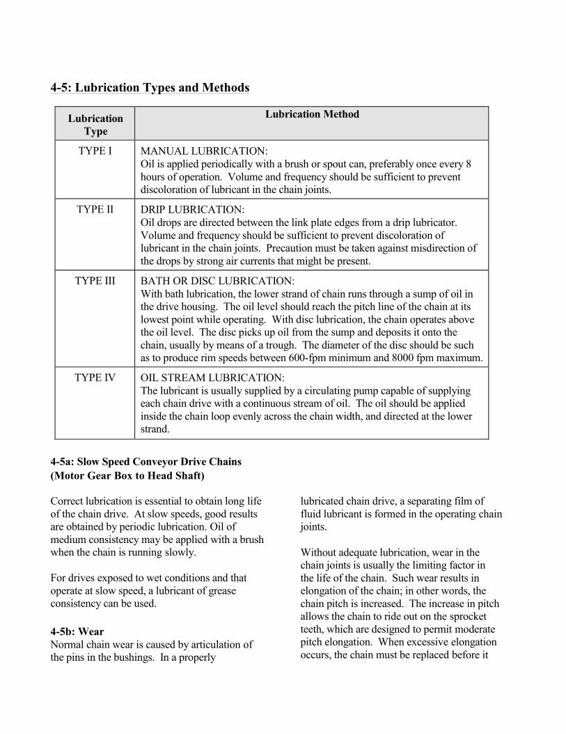
4-5: Lubrication Types and Methods
Lubrication Type
Lubrication Method
TYPE I MANUAL LUBRICATION: Oil is applied periodically with a brush or spout can, preferably once every 8 hours of operation. Volume and frequency should be sufficient to prevent discoloration of lubricant in the chain joints.
TYPE II DRIP LUBRICATION: Oil drops are directed between the link plate edges from a drip lubricator. Volume and frequency should be sufficient to prevent discoloration of lubricant in the chain joints. Precaution must be taken against misdirection of the drops by strong air currents that might be present.
TYPE III BATH OR DISC LUBRICATION: With bath lubrication, the lower strand of chain runs through a sump of oil in the drive housing. The oil level should reach the pitch line of the chain at its lowest point while operating. With disc lubrication, the chain operates above the oil level. The disc picks up oil from the sump and deposits it onto the chain, usually by means of a trough. The diameter of the disc should be such as to produce rim speeds between 600-fpm minimum and 8000 fpm maximum.
TYPE IV OIL STREAM LUBRICATION: The lubricant is usually supplied by a circulating pump capable of supplying each chain drive with a continuous stream of oil. The oil should be applied inside the chain loop evenly across the chain width, and directed at the lower strand.
4-5a: Slow Speed Conveyor Drive Chains (Motor Gear Box to Head Shaft) Correct lubrication is essential to obtain long life of the chain drive. At slow speeds, good results are obtained by periodic lubrication. Oil of medium consistency may be applied with a brush when the chain is running slowly. For drives exposed to wet conditions and that operate at slow speed, a lubricant of grease consistency can be used. 4-5b: Wear Normal chain wear is caused by articulation of the pins in the bushings. In a properly
lubricated chain drive, a separating film of fluid lubricant is formed in the operating chain joints. Without adequate lubrication, wear in the chain joints is usually the limiting factor in the life of the chain. Such wear results in elongation of the chain; in other words, the chain pitch is increased. The increase in pitch allows the chain to ride out on the sprocket teeth, which are designed to permit moderate pitch elongation. When excessive elongation occurs, the chain must be replaced before it

overrides the sprocket teeth. Proper lubrication of the bearing surfaces of the chain joints is of major importance in retarding wear. 4-5c: Double Pitch Chain Double pitch chains of the straight side bar series are commonly used in conveyor applications. Loads can be supported on attachments or the chain plates. The chain may be allowed to slide or may be supported on oversize rollers. To determine chain loading, each application must be analyzed and the appropriate coefficient of friction determined. 4-5d: Conveyor Chains Conveyor chains should be kept as clean as operating conditions will permit for the purpose of fostering effective lubrication to minimize metal-to-metal contact of pin- bushing and bushing-roller joints. Oil should be applied to upper edges of all link plates while in the lower span of chain since access to joint clearances is possible only through clearances between roller link plates and rollers. A good grade of oil, of medium or light consistency, free flowing at the prevailing temperature, should be used. Note: Where location of equipment dictates the use of FDA approved lubricants, only those lubricants so approved should be used. Tracks may be lubricated with a free flowing oil the same as for chain joint lubrication or, if desirable, with a more viscous oil having better adherence to the track and providing better lubrication for conditions where link plate edges are sliding on the supporting track.
4-5e: Sprockets Sprockets for double pitch chains with standard rollers can be furnished in either Single Tooth Form or Double Tooth Form. Double Tooth cutting actually doubles the life expectancy of the sprocket. Chain rollers contact only every other tooth. When these teeth become worn after long service, the sprockets can be advanced one tooth, thus permitting chain engagement on a new series of sprocket teeth. 4-6: Lubrication and Care of Sealed Ball Bearings Rotating drive, idler and take-up shafts have sealed self-aligning ball bearings. Ball bearing units are shipped prelubricated with grease chosen for chemical and mechanical stability. Bearings designed for relubrication should be relubricated periodically with the length of interval between greasing being dependent on the running speed and atmospheric conditions. For normal operating conditions, a grease should be used which conforms to NLGI No. 2 consistency and is free of any chemical impurities such as free acid or free alkali or any mechanical impurities such as dust, rust, metal particles or abrasives.

Grease used in bearings has an operating temperature (up to 200°F., with occasional highs of 250°F.), a low cold test (minus 30°F.). For lubrication of bearings under abnormal operating conditions, consult NERCON for specific recommendations. Bearings should be relubricated while in operation wherever possible. Grease should be pumped in slowly until a slight
bead forms around the seals. This bead, in addition to acting as an indicator of adequate relubrication, provides additional protection against the ingress of dirt. Relubrication is generally accompanied by a rise in the operating temperature of the bearing. When the slight grease bead is formed, it should be noted that the temperature will rise approximately 30°F.
4-6a: Conditions Table
The following table covers most situations:
SPEED
TEMPERATURE
CLEANLINESS GREASE
INTERVAL
100 RPM Up to 120° F.
Clean
6 to 12 months
500 RPM Up to 150° F. 2 to 6 months
1000 RPM Up to 210° F. 2 weeks to 2 months
1500 RPM Over 210° F. Weekly
Any Speed
Up to 150° F. 1 week to 1 month
Over 150° F. Dirty
Daily to 2 weeks Any Temperature Very Dirty
Extreme Conditions

4-7: Tabletop Chain Lubrication
Whenever the application permits, lubrication is recommended. It not only reduces friction, thereby reducing chain tension, but it also greatly improves the wear life of the chain and wearstrips. Be sure the lubricant coats both the chain and wearstrip mating surfaces. It is necessary to apply lubricant at the entrance of the inside curves.
If lubrication is not compatible with the application, a brief break-in lubrication application is beneficial. Apply a light mineral oil to sideflexing chains prior to installation. Also, apply oil to tabletop base roller chains prior to installation.
4-8: Periodic Inspection
In the course of conveyor operation, periodic inspection of the chain, sprockets, and system is required to detect faults and make repairs before serious damage occurs. The important thing is to set up a regular inspections and maintenance schedule.
4-8a: Tabletop Conveyor Checklist
1. Look for unusual wear patterns on the
chain. 2. Inspect chain for lack of top surface
flatness. 3. Check for excessive gap between flights
due to jam-up or overload. 4. Pulsating or jerky chain operation
indicates poor lubrication or conveyor obstruction.
5. Check deadplate and turntable clearance. 6. Examine sprockets for signs of excessive
wear. 7. Examine sprockets for signs of dirt
build-up in tooth pockets. 8. Check for sprocket guide ring wear and
possible chain misalignment.
9. Check the ways and wearstrips for
excessive wear. 10. Inspect lubrication system for proper
operation. 11. Check the inside of curves and the
supporting conveyor frame for excess heat build-up, which may indicate an obstruction in the curve or a high friction area.
12. If return support rollers are used, check to insure rollers are free turning.
4-8b: Repair and Replacement Any malfunctions found during an inspection usually stem from one or more of the following conditions: 1. Severe overloads, jam-ups, or wedging of
broken glass or crowns. 2. Severe back-flexing of chain on the return
carrying ways. 3. Poor lubrication or no lubrication. 4. Interference and obstruction. 5. Worn sprockets. Chain and/or sprockets should be replaced when: 1. The chain measures approximately 123
inches in 120 flights for 843 chain; in 40 flights for 2873 chain; in 61 pitches for 1700 chain; and in 80 flights for all other chain.
2. The chain jumps the sprockets. 3. The flights have worn to about one-half of
the original thickness. 4. The conveying surface becomes uneven
through wear. 5. The thrust surface of sideflexing chains
wears away and exposes the rivet or other metal parts, which may cut into wearstrips or other conveyor components.
6. The sprockets teeth develop a hooked profile or the chain tends to “hang-up” on the sprocket teeth.

4-8: Periodic Inspection (Cont.) 4-8c: Belt Conveyor Checklist
1. Be sure all rollers and pulleys rotate freely.
2. Check for unusual wear on belt, pulleys,
rollers, or bed. 3. Check drive chain and sprockets for wear.
4. Check pulley , shaft, and bearing
relationships for indications that pulleys or shafts are “walking,” or moving from their original position.
5. Follow installation, lubrication, and
maintenance instructions for specific components, per brochures or manuals shipped with the equipment.
4-9: Cleaning
4-9a: Chain Conveyor
In many applications, rapid build-up or grease, dirt, grit, sand, and spilled product can occur. These result in:
1. Soiling and damage to the conveyed
product. 2. Increased work demands for the chain
and motor. 3. Accelerated sprocket tooth wear. 4. Conveyor pulsation and wear. 5. Excessive chain wear on the flight and in
the joint areas. 6. Rapid wear of the wearstrips.
Frequent cleaning of the chain and conveyor frame is advised. Such agents as steam, warm water and soap are commonly used. Many times combined “cleaners/lubricants” are applied continuously. Strong caustic agents used with metal chains should not be used with
plastic chains. Always rinse cleaning agents completely off of chain and conveyor frame. When excessive amounts of syrup or other liquids, broken glass, or debris accumulate, cleaning will be required on a regular basis to remove these undesirable materials. It is advisable to have operating personnel keep brushes and cleaning solutions nearby to remove broken glass and excessive spillage.
4-9b: Belt Conveyor The accumulation of product or foreign matter on the belt, pulleys, rollers, conveyor bed and other components can greatly affect the belt tracking and the life of the belt and conveyor. 1. Establish a cleaning schedule that prevents
product or dirt build-up based on plant production conditions.
2. If cleaning agents are used, be sure they are compatible with the belt and all conveyor components.
3. If product sticks to belt, a belt scraper or powered brush may be required. Consult the factory.
If products or residue is migrating from the belt to the conveyor frame and/or pulleys, a scraper or brush for the backside of the belt may also be required.

Section 5: Troubleshooting
5-1: Troubleshooting Guide 5-1a: Tabletop Chain Conveyor
! Pulsing-check the amount of catenary sag. If too much sag, the chain can cause pulsing. It is normal for the chain to stretch during initial break-in. Possibly requiring removal of one (1) or more links.
! Jerking-check guide clearance in raceways, curves (both top and return side) ! Squeaking-may require lubrication; try silicone spray for temporary relief; clean the raceways ! Overheating motor-check all items in installation section. Be sure motor is properly wired ! Chain speed running slow-be sure motor isn’t single phasing ! Jumping sprockets-check catenary sag Check for chain stretch Check sprocket alignment
These suggestions on chain and conveyor care serve as a guide toward maintaining continuous, trouble-free operation. Implementation of a conscientious programmed maintenance schedule will lead to many productive hours of conveyor operation. If a problem persists, consult a Nercon representative for service.
5-1b: Belt Conveyor
! Motor overheating-be sure all items of installation section have been followed
Be sure motor is properly wired. Be sure conveyor, belt and drive are clean and free of obstructions. Be sure that all pulleys, rollers and bearings are properly lubricated and rotate freely Belt tension may be excessive
! Belt speed is slower than design speed-Be sure motor is not single phasing Belt may be slipping on drive pulley-increase tension
! Belt tracking --One part of belt moves to one side
Belt splicing not properly vulcanized Belt ends not cut square or fasteners not put into belt squarely If not located at splice area, belt may have an irregularity or been damaged.
--Entire belt moves to one side Conveyor frame or supports may cause bed to not be horizontal and cause belt to drift Product or dirt build-up on pulleys, rollers or bed. Improper loading, load needs to be centered on belt and loaded in direction of travel Pulleys or rollers out of line or not rotating

5-1b: Belt Conveyor (Cont.) --Belt moves to one side at one location
Pulley or roller immediately preceding this location is out of line or not rotating Frame or support prior to this location may cause bed not to be horizontal and cause belt to drift Product or dirt build-up on pulleys, rollers or bed Improper loading at or prior to the problem location
--Belt creeps to one side at head or tail pulley Pulley or rollers immediately proceeding are out of line See also #3
! Belt tracking (cont.)
--Belt wanders irregularly Improper loading, load needs to be in center of belt and loaded in direction of flow Belt may be too stiff to operate over pulley diameters supplied
--Excessive belt stretch Belt tension may be excessive. Reduce tension, but be sure belt is not slipping on drive pulley and that belt conforms to crown of pulley. Pulleys or rollers may have material build-up or may not be rotating. Belt may be inappropriate for tension required
--Splice failure Belt tension may be excessive Pulley diameter is too small Belt speed is excessive for design Incorrect size or type of fastener used Improper splice kit or method of vulcanization
--Excessive belt wear Pulley diameter is too small Pulleys or rollers may have material build-up Excessive impact of material on belt Belt slipping on drive pulley Damage from heat, chemicals, mildew, abrasives or oil Belt edges frayed due to rubbing on side frames

5-1c: Components
Problem
Possible Cause
Corrective Action TIMING BELT DRIVE SHEAVE
Abnormal wear. Excessive belt tension. Reduce belt tension.
Sheaves improperly aligned. Realign with straight edges across sheave faces.
Damaged sheaves or belt. Replace the damaged component.
Excessive belt slippage. Increase belt tension.
Misalignment of chain guard. Remove and adjust as appropriate.
Dirty chain. Clean thoroughly and lubricate.
ROLLERS, SHAFTS, AND DRIVES
Rollers do not turn. Roller bearing is damaged or defective. Replace roller.
Drive belt broken or defective.
Inspect for any interference or rubbing condition. Remove and replace belt.
Drive belt out of O-ring groove. Realign belt to groove.
5-1c: Components (Continued)
Problem
Possible Cause
Corrective Action ROLLERS, SHAFTS AND DRIVES
Rollers do not turn (continued).
Excessive spool slippage on shaft. Inspect for possible contaminants on the shaft.
To clean the contaminants, the shaft, spools, and C-clips must be removed. Clean the shaft with a dry cloth and/or high evaporating cleaning agent such as naphtha or alcohol.
Shaft does not rotate. Motor not running. See the gearmotor vendor documentation in Appendix B.
Shaft coupling sprocket failure. Replace the shaft-coupling sprocket.
Drive timing belt failure. Check timing belt for slippage or damage. Adjust or replace.
Drive belt slippage. Possible contamination or chemical reaction.
Eliminate source of contamination; clean belt.
Extreme temperature. Replace drive.
Note: Please refer to the vendor documentation for troubleshooting for gearmotors.

5-1d: Electrical System Occasionally a malfunction may occur because of broken connecting wires, loose connections, and/or dirty or corroded terminals. Such causes can be detected by visual inspection and continuity checks. It is more likely the fault would be in the motor control panels or due to a defective or malfunctioning component or part. 5-1e: Motor Control Panel Plant power is fed into the motor control panel through a disconnect device. Fused power is supplied to the motors, which operate the system. Most motors have additional controls, which tie into the system. Lack of drive on any assembly indicates that the first checks should be made of the electrical controls in the motor control panel.
Warning This disconnect must always be shut down and locked out during any maintenance operation. 5-1f: Safety Interlocks The interlock circuit prevents an action occurring until one or more related actions have taken place. The interlock action is controlled by relays or by the programmable controller. The interlock circuits are activated by limit switches or photoelectric cells. An inoperative interlock can disrupt the entire system operation.
5-1g: Photo Electric Cells Many system operations are activated by the interruption of a light beam emitted by a photoelectric cell. There are three major types of PE's used on our equipment: 1. Through Beam Detection (sender/
receiver). The sender (emitter) and receiver (detector) are mounted on opposite sides of an object to be detected. When an object breaks the beam of light, a switch is activated.
2. Proximity Detection. The light source
and receiver are mounted in a common housing. Detection occurs when an object enters the area and the source beam is deflected from the detected object to the receiver.
3. Reflex (retro-reflective detection).
The light source and receiver are mounted in a common housing, with light beam directed at a retro-reflector. Detection occurs when an object breaks the beam of light.
Troubleshooting should include checking alignment of photoeyes, cable connections, and cleanliness.

5-1h: Limit Switches A limit switch is a mechanically operated switch, activated by a moving object. The switch uses changes in mechanical motion to activate electrical circuits, which then causes a mechanical action such as applying a brake or starting motion. Troubleshooting and corrective action, if required, consists of visual and possible physical checks of movement.
5-1i: Relays Relays are electro-mechanical devices with multiple contacts which open and close in response to electrical circuit conditions. The action of one device, such as a sensor switch, can cause the reaction of a related device such as a drive motor. The conveyors may use photo electric cells, proximity switches and limit switches as sensors to activate the control relays through the programmable controller. 5-1j: Pneumatic Systems Some components may be pneumatically operated by regulated air supplied through air hoses, valves and assorted fittings. If erratic action or malfunctions occur with these assemblies, check the airlines, valves and fittings for leaks.
5-1k: Mechanical Assemblies and Equipment Mechanical malfunctions or trouble are usually caused by misalignment, loosened fastening devices, sheared pins and worn or broken parts. Once the trouble has been located, the corrective action requires adjustment, realignment, tighten loose fasteners and occasionally replacement of a worn or broken part. Corrective action applied in time can prevent major maintenance and parts replacement in the future.

Section 6: General Maintenance Guidelines
(See item specific OEM brochures and OEM manuals that are provided with the equipment for specific component maintenance.)
6-1: Worm Gear Reducers:
TYPE OF MAINTENANCE
WHEN TO DO WHAT TO DO
Lubrication Initial change - 2 weeks. Second change - 1 month. Every 4 months thereafter
Drain the oil while warm. On initial change, flush box with a light weight (5W or 10W) synthetic oil. Fill box to recommended level with fresh recommended oil. In vertical shaft operation, lubricate the top bearing with each oil change.
Lubrication level check Initial inspection - 24 hours. Every 100 hours thereafter.
Check for proper oil level. If oil is required, check for leakage.
Check mounting bolts Initial inspection - 24 hours. Second inspection - 100 hours.
Check mounting bolts for tightness. Be sure reducer has not moved. Retighten bolts, if necessary
6-2: Spiral Bevel Gear Box (Right Angle)
TYPE OF MAINTENANCE WHEN TO DO WHAT TO DO Lubrication Initial change - after first 100 hours.
Every 2500 hours or 6 months, whichever comes first, thereafter
Drain used oil from box. Flush box if oil has become contaminated. Refill to proper level with new lubricant.
Lubrication level check Initial inspection - 24 hours. Second inspection - 100 hours. Third inspection - 500 hours. Periodically thereafter.
Check oil level. Add oil, if necessary. If oil is required, check for leakage.
Check mounting bolts Initial inspection -24 hours. Second inspection - 100 hours. Third inspection - 500 hours. Periodically thereafter.
Check mounting bolts for tightness. Be sure reducer has not moved. Retighten bolts, if necessary
6-3: Shaft Mount Reducers
TYPE OF MAINTENANCE WHEN TO DO WHAT TO DO Lubrication Initial change - after first 100 hours. At
least once per year thereafter. More often if atmosphere is damp or dusty.
Drain used oil from box. Flush box if oil has become contaminated. Refill to proper level with new lubricant.
Lubrication level check Initial inspection - 24 hours. Second inspection - 100 hours. Third inspection - 500 hours. Periodically thereafter.
Check oil level. Add oil, if necessary. If oil is required, check for leakage.
Torque arm Initial inspection - 24 hours. Second inspection - 100 hours. Third inspection - 500 hours. Periodically thereafter.
Tighten bolts and nuts that hold the torque arm in place on the reducer and on the mounting surface.
Torque Taper bushing and finished bore bushing
Initial inspection - 24 hours. Second inspection - 100 hours. Third inspection - 500 hours. Periodically thereafter.
Check setscrews or cap screws for tightness. Retighten to recommended torque, if necessary.

6-4: Synchronous Belt Drives
TYPE OF MAINTENANCE WHEN TO DO WHAT TO DO Check belt tension Initial inspection - 8 hours. Second
inspection - 40 hours. Third inspection - 100 hours. Periodically thereafter.
Adjust belt centers to take up accumulated slack. When the drive is in operation, both sides of the belt should be straight from pulley to pulley.
Check pulley alignment Initial inspection - 8 hours. Second inspection - 40 hours. Third inspection - 100 hours. Periodically thereafter.
If there is evidence of severe wear on pulley flanges and/or belt edges, the drive is misaligned. Correct alignment to prevent premature failure.
Check setscrews and/or bushing cap screws
Initial inspection -8 hours. Second inspection - 40 hours. Third inspection - 100 hours. Periodically thereafter.
Check all setscrews and/or bushing cap screws for looseness. Tighten to recommended torque, if necessary.
6-5: V-Belt Systems
TYPE OF MAINTENANCE WHEN TO DO WHAT TO DO Check for sheave groove wear
Initial inspection 8 hours. Second inspection - 24 hours. Third inspection -100 hours. Periodically thereafter.
Check for belt ride in the groove. In multiple groove drives, belt ride should be uniform, not more than 1/16” above or below top of sheave groove. Check groove wear area for wear. Side wall of groove should be straight, not dished out. Bottom of groove should show no signs of belt contact.
Check for sheave runout Initial inspection - 8 hours. Second inspection - 24 hours. Third inspection - 100 hours. Periodically thereafter.
Check sheave by eye for runout. If runout is excessive, it can easily be seen by visual inspection. If runout is noticeable, check sheave for source of problem and correct.
Inspect for heat build-up and proper ventilation
Initial inspection -8 hours. Second inspection - 24 hours. Third inspection - 100 hours. Periodically thereafter.
Check belts for heat. Ambient temperature should not exceed 140°F. Contact temperature should not exceed 180°F. Make sure drives are properly ventilated.
Clean belts and sheave grooves
Initial inspection -8 hours. Second inspection - 24 hours. Third inspection - 100 hours. Periodically thereafter.
Inspect belts for contaminates, such as oil or grease. Wipe belts clean with detergent and water. Inspect sheave grooves for buildup of such material and remove, if necessary.
Check belt tension Initial inspection -8 hours. Second inspection - 24 hours. Third inspection - 100 hours. Periodically thereafter.
Check belt tension using belt tension checker. Tension to manufacturing recommendations.
Check sheave alignment Initial inspection -8 hours. Second inspection - 24 hours. Third inspection - 100 hours. Periodically thereafter.
Check alignment with straight edge, string or machinist level. Correct alignment to as near perfect as possible.
Mismatched belt check Initial inspection -8 hours. Second inspection - 24 hours. Third inspection - 100 hours. Periodically thereafter.
Check belt sag on slack side of drive. All belts should have a slight bow. If this bow is not uniform with all belts, replace entire set with a matched set.
Check for worn belts Initial inspection -8 hours. Second inspection - 24 hours. Third inspection - 100 hours. Periodically thereafter.
Check wear surfaces of belt for excessive wear. If belts have a slick, glazed look, belts are slipping. Check drive capacity and belt tension. Never replace only one belt in a used set, as used belts will elongate. Replace entire set if replacement is necessary.
Check sheave setscrews and/or bushing cap screws
Initial inspection -8 hours. Second inspection - 24 hours. Third inspection - 100 hours. Periodically thereafter.
Check all setscrews and/or bushing cap screws for looseness. Retighten to recommended torque, if necessary.

6-6: Timing Belt Drives
TYPE OF MAINTENANCE WHEN TO DO WHAT TO DO Check belt tension Initial inspection -8 hours. Second
inspection - 24 hours. Third inspection - 100 hours. Periodically thereafter.
Check belt tension using BROWNING belt tension checker or similar spring scale. When the drive is in operation, both sides of the belt should be straight from pulley to pulley.
Check sheave alignment Initial inspection - 8 hours. Second inspection - 24 hours. Third inspection -100 hours. Periodically thereafter.
Check alignment with straight edge, string or machinist level. Correct alignment to near perfect as possible.
Check for worn belts Initial inspection -8 hours. Second inspection - 24 hours. Third inspection - 100 hours. Periodically thereafter.
Check wear surfaces of belts for excessive wear. If belts have a glazed look, belts are slipping. Check belt capacity and belt tension and sheave alignment.
Check sheave setscrews and/or bushing cap screws
Initial inspection -8 hours. Second inspection - 24 hours. Third inspection - 100 hours Periodically thereafter.
Check all setscrews and/or cap screws for looseness. Retighten to recommended torque, if necessary.
Check sheave runout Initial inspection -8 hours. Second inspection - 24 hours. Third inspection - 100 hours. Periodically thereafter.
Check visually for sheave runout. If runout is noticeable, check for source of problem and correct.
Check for sheave groove wear
Initial inspection -8 hours. Second inspection - 24 hours. Third inspection - 100 hours. Periodically thereafter.
Check groove wear area for excessive wear. Side wall of groove should be straight, not dished out.
Inspect for heat buildup and proper ventilation
Initial inspection -8 hours. Second inspection - 24 hours. Third inspection - 100 hours. Periodically thereafter.
Check belts for heat. Ambient temperatures should not exceed 140°F. Peak contact temperature should not exceed 180°F. Be sure all drives are properly ventilated.
Clean belts and sheave Initial inspection -8 hours. Second inspection - 24 hours. Third inspection - 100 hours. Periodically thereafter.
Inspect belts for contaminants such as oil or grease. Wipe belts clean with detergent and water. Inspect sheave grooves for buildup of such material and remove, if necessary.

6-7: Bearings
TYPE OF MAINTENANCE
WHEN TO DO WHAT TO DO
Check setscrews Initial inspection - 24 hours. Second inspection - 100 hours. Third inspection - 500 hours. Periodically thereafter
Check setscrew tightness. Retighten, if necessary.
Locking collars Initial inspection - 24 hours. Second inspection - 100 hours. Third inspection - 500 hours. Periodically thereafter.
Check eccentric collar tightness on shaft. If loose, turn in the direction of shaft rotation until hand tight. Then tighten the collar setscrew to the torque values recommended.
Lubrication Operating Bearing Grease Conditions Temperature Interval Clean
32 - 120°F 6-12 mo. 20 - 150°F 1-3 mo.
150 - 200°F 1-4 wks. Dirty 32 - 150°F 1-4 wks.
150 -200°F Daily - 1wk Moisture 32 - 200°F Daily - 1 wk
Add grease slowly with drive in operation. When lubricant begins to come out of the seals, the bearing will contain the correct amount of lubricant.
Check mounting bolts Initial inspection -24 hours. Second inspection - 100 hours. Third inspection - 500 hours. Periodically thereafter
Check mounting bolts for tightness. Retighten, if necessary.
Check bearing alignment
Initial inspection -24 hours. Second inspection - 100 hours. Third inspection - 500 hours. Periodically thereafter
Check bearing alignment. Note if bearing may have slipped or moved since installation.
Check for damaged seals
Initial inspection - 100 hours. Second inspection - 500 hours. Periodically thereafter.
Check seals to make sure they have not been punctured or damaged by foreign objects.
Check bearing temperature
Initial inspection -24 hours. Second inspection - 100 hours. Third inspection - 500 hours. Periodically thereafter
Check to see if bearing is running hot. Bearing temperatures should not exceed 200°F.
Check for bearing noise
Initial inspection -24 hours. Second inspection - 100 hours. Third inspection - 500 hours. Periodically thereafter
Check for bearing noise. Bearing should have a soft, smooth purring sound.

6-8: Electric Motors (AC & DC)
TYPE OF MAINTENANCE WHEN TO DO WHAT TO DO Lubrication Approximately once per year
depending upon surrounding conditions.
Lubricate motor bearings with a high grade grease. Be careful not to over lubricate bearings.
Clean Every 6 months. Using moderate air pressure (25 -30 PSI) blow out dirt from windings, and wipe commutator and brushes or slip rings.
Check brushes and Commutator (DC)
Every 6 months. Check brushes and brush holders. Clean holders if dirty. Be sure brushes ride free in holders. Replace brushes if more than half worn. Inspect and clean commutator slots. All wiping should be with a lint-free cloth. Commutator should be cleaned with a lint-free cloth and carbon tetrachloride.
Connector inspection Every 6 months. Inspect and tighten all connections on motor and control
Current check Every 6 months. Check current draw and compare with normal.
Check for vibration and mounting bolts
Every 6 months. Retighten all mounting bolts. Run motor and examine carefully for smooth running, absence of vibration.
6-9: Variable Frequency Drives
TYPE OF MAINTENANCE WHEN TO DO WHAT TO DO Keep control clean As necessary, depending on
surrounding conditions For best operating results, keep all dust, oil grease away from control. Wipe exterior clean with a clean cloth. Blow inside of control clean with moderate air pressure (25 - 30 PSI) if necessary.
Connector inspection Every 6 months. Inspect and tighten all connections Current check Every 6 months. Check line and motor currents and
compare with normal Motor Every 6 months. Refer to Motor Maintenance Section

Section 7: Gripper
7-1: Container Grip Setting
A. Turn hand wheel width adjustment handle to move gripper bulb gap to approximately 1/8” less than diameter of sample container.
B. Set drive at minimum speed and release a single container onto the infeed conveyor.
C. Run single container thru full length of unit, stopping periodically to check for tight or especially loose points. Note: Container should stay in its original position in relation to the gripper chain for the full trip thru the unit.
D. Run multiple containers thru the full length of the unit, checking as above. 7-2: Line Control
The single most important item in the operation of the Gripper Elevator or Lowerator is the correct spacing of containers as they are fed into the unit. Normal operation causes incoming containers to “close-up” as they travel through the vertical curves. Calculate the speeds of the infeed conveyor, discharge conveyor and gripper drive:
A. Determine the amount of space required to eliminate container contact as containers move around the revolving discs.
B. Size the conveyor and rinser drives speeds to gap containers to eliminate container contact in the curves.
C. The system should be started sequentially, with the downstream conveyors starting first, then the Gripper unit, then the upstream conveyors. Each segment should be at line speed prior to starting the next segment.
D. If this noted container gap is not taken into consideration: Containers will be forced up or down in the gripper bulbs allowing them to:
1. Drop out of the bulbs 2. Force containers into the discharge conveyor and breaking containers or
conveyor chain. 3. Causing excessive gripper bulb wear form “scrubbing action”.
7-3: Lubrication
The Gripper construction breaks down to the following areas to be considered for lubrication:
A. Gripper Chain: Unless you are running very high speed (in excess of 250’ per minute) additional lubrication of the chain is not required.
B. Conveyor and horizontal width adjustment shaft cartridge bearings. C. Main drive and conveyor drives, Reliance parallel reducer and right angle
gearboxes: See Reliance literature with specific requirements for lubrication, frequency of lube change, and service.
E. Acme thread and brass blocks on horizontal width adjustment shafts. Hand application of grease directly to shafts.
F. Lubrication Frequency: See standard Nercon manual for Table Top and Belt conveyors

7-4: Mechanical Adjustments
A. GRIPPER CHAIN TENSION
1. Any machine shipped in one piece will have the gripper chain installed and the tension set for correct operation.
2. During set up, the chain should be checked for correct tension and chain wear-in. Considering approximately 60’ of chain per side a wear-in of .001 inch per link would equal
3. The chain tension nut is welded to a “spring sleeve” which is approximately 3/8” longer than the spring compressed length. This insures that the spring will not bottom out even if the sleeve is bottomed out. The spring sleeve should be adjusted to within 1/8” to ¼” from bottoming out.
4. When the take up has been “taken-up” approximately ¾” to 1” it is suggested that a chain link be removed from the chain, and the spring sleeve readjusted per #3 above.
B. CHAIN LINK REMOVAL (SPLICING CHAIN)
1. The two standard chains supplied with the gripper are the Rex LF1873GD or GJ and the LF1873SSGD or GJ. Both chains are side flexing #60 roller chains with a color coded plastic link at each masterlink location. LF882Tab-GD or GJ plastic unit link chains may also be supplied.
2. To remove the gripper bulb, grip the bulb in one hand, compressing it from both ends and bowing the bottom to clear one tab of the plastic top plate.
3. When replacing a bulb, compress as above and check from both sides to confirm that the plastic tab of the top flite is over the top of the bulb bottom surface rather than “Digging In” to the side of the surface.
4. Considering that the chain tabs are under the wearstrips for most of the machine, the location to remove a chain link is on the back side of the sprocket on the spring loaded take up just before the chain tab enters the wearstrip.
5. After removing the bulb, use a thin screw driver between the roller chain and plastic side plate covering the chain and pry the plastic away from the chain while pulling the outer end of the plastic flite away from the chain (back flexing top flite).
6. After removing the color-coded top flite, the master link of the chain will be exposed and the chain can be separated.
7. If a link is to be removed, use a small hand grinder and grind off the crimped ends of the chain connecting pins. After grinding off the pins, use a straight punch, and supporting the chain on the sprocket, punch the pins through the chain link. Reassemble the chain using the masterlink and then install the top flite and gripper bulb.
C. DRIVE
The drive consists of a pair of Reliance “C” face motors and right angle, C face, hollow shaft reducers, connected directly to the two conveyor drive shafts. No adjustments are required. Check sprocket teeth for wear. 1. Lubrication: See enclosed literature for lubrication requirements on the reducers and universal joints. 2. Service: Check gripper chains for correct tension and grip. See previous sections.

D. PRODUCT GRIP ADJUSTMENT
1. Pressure adjustment is made through turning the single hand wheel located on the side of the Gripper framework.
2. The amount of gripper “bulb” deflection will vary depending on the weight and rigidity of the container. The staring point is the minimum pressure required to keep the container from slipping in the bulbs.
3. A consistent gap between the bulbs is important and should not vary more than + 1/8” throughout the complete length of the machine.
4. If a variation greater than mentioned is noted or containers are noted to slip in certain locations, the following method should be used to adjust chain spacing. At a minimum of three locations, an adjusting shaft supported with brass Acme nuts determines the chain spacing. All of these shafts are connected by roller chain to the single hand wheel adjustment. To increase or decrease chain spacing:
A. Select the closest adjusting shafts to the location requiring adjustment. B. Measure the average gap distance within 1/32”. C. Remove the bolts holding the “cage” bars around the square brass Acme nut. D. Turn the nut ¼ turn tighter or loose (depending on bulb grip requirement). E. Replace the nut “cage” bars and nylock nuts. *Note: To insure a free fit the
“cage” bar bolts are NOT drawn down tight. F. Remeasure the gap distance and compare to original dimension. Redo steps
3, 4 & 5 if necessary. 7-5: Cleaning
Cleaning methods are the same as those used for the table top conveyors. All cleaning agents and sanitizers should be proven not to attack acetal plastics, rubber, bearing seals, nickel plating, types 303 and 304 stainless steel, or painted construction if so provided.