Installation and Service Instructions - Pump · Installation and Service Instructions Version...
15
Installation and Service Instructions Excellence at work. Excellence in life. Version C Series Pumps
Transcript of Installation and Service Instructions - Pump · Installation and Service Instructions Version...

Installation and Service Instructions
Excellence at work. Excellence in life.Version
C Series Pumps
Version Page 2 of 15
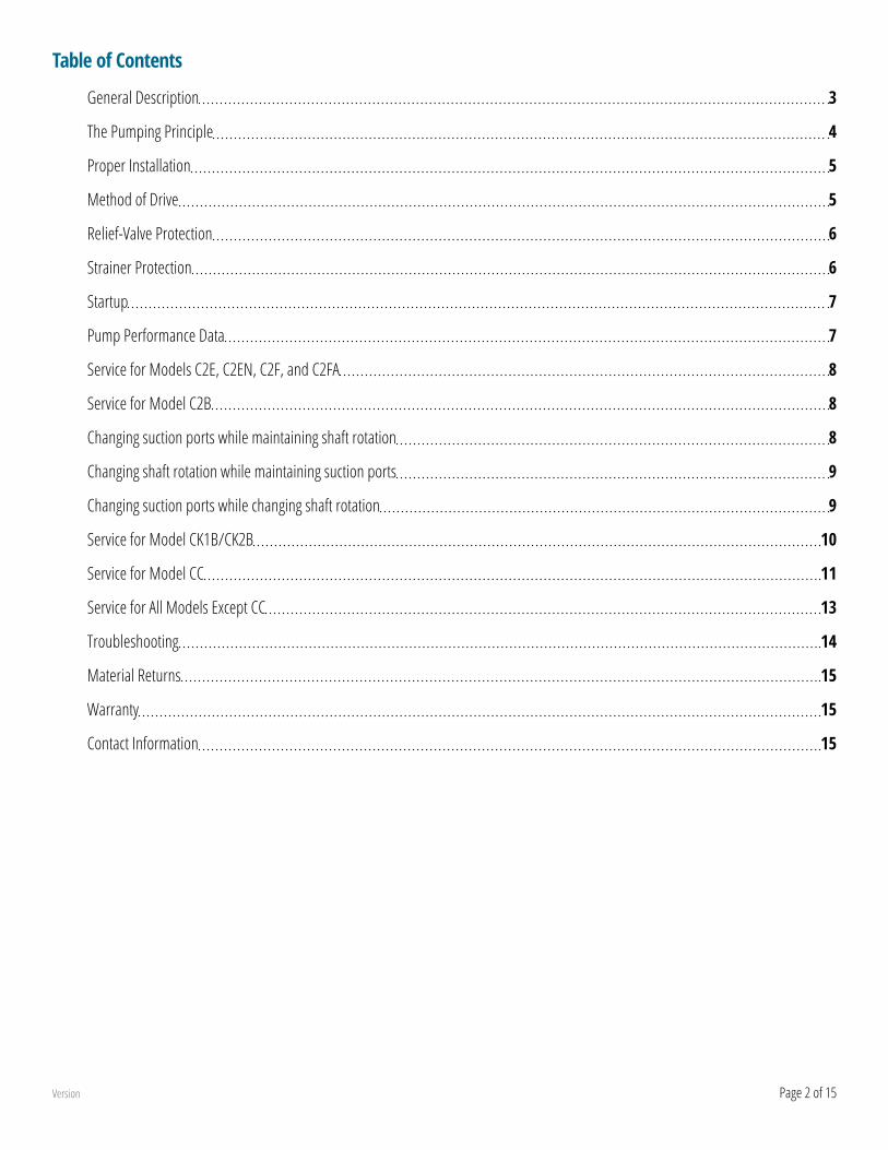
Table of Contents
General Description 3
The Pumping Principle 4
Proper Installation 5
Method of Drive 5
Relief-Valve Protection 6
Strainer Protection 6
Startup 7
Pump Performance Data 7
Service for Models C2E, C2EN, C2F, and C2FA 8
Service for Model C2B 8
Changing suction ports while maintaining shaft rotation 8
Changing shaft rotation while maintaining suction ports 9
Changing suction ports while changing shaft rotation 9
Service for Model CK1B/CK2B 10
Service for Model CC 11
Service for All Models Except CC 13
Troubleshooting 14
Material Returns 15
Warranty 15
Contact Information 15

Version Page 3 of 15
General Description
Models C2E, C2EN, C2F, and C2FA
Model C2E and C2F pumps are sleeve bushing lip seal units designed for direct drive service. Model C2E comes with the foot assembled to the pump. Model C2F is a flange mount pump. Model C2FA pumps are similar to model C2F but are supplied without a seal. Model C2EN pumps are sleeve and ball bearing units with a lip seal and mounting foot designed for indirect (belt, chain, gear) drive. The seal chamber on these pumps is vented to the suction side of the pumping zone. Therefore, the pump must operate in the direction for which it is assembled. All models are available in five sizes, ranging in capacity from 6 to 84 gpm with differential pressures to 100 psi. The maximum discharge pressure capability is 100 psi.
Model C2B
Model C2B is a flange-mount pump with two sleeve type bushings and a mechanical seal. The seal chamber on these pumps is vented to the suction side of the pumping zone. Therefore, the pump must operate in the direction for which it is assembled. This pump is available in five sizes, with capacities from 6 to 84 gpm and differential pressures to 150 psi. The maximum discharge pressure capability is 300 psi. A mounting foot is optional.
Model C2G
Model C2G is equipped with spring-loaded V-type graphite-impregnated PTFE packing. Model C2G pumps have the packing chamber vented to the suction side of the pumping zone. Therefore, the pump must operate in the direction for which it is assembled. There are five sizes, ranging in capacity from 6 to 84 gpm with differential pressures to 100 psi. The maximum discharge pressure capability is 125 psi.
Model CK1B
Model CK1B pumps are equipped with a mechanical seal and incorporate heavy-duty features, including special double-bearing construction with an inboard double ball bearing and an outboard roller bearing. There are five sizes, with capacities from 6 to 84 gpm and differential pressures to 250 psi. The maximum discharge pressure capability is 300 psi. A mounting foot is optional. The seal chamber is vented to the suction side. Therefore, the pump must operate in the direction for which it is assembled.
Model CC
Model CC pumps are designed to mount directly to NEMA 56, 143TC or 145TC C Face motors. They are equipped with a mechanical seal and will pump equally well in either direction of rotation (unless equipped with an internal relief valve). These pumps are available in four sizes, with capacities from 9 to 30 gpm. They can handle inlet pressures to 25 psi and differential pressures to 100 psi.

Version Page 4 of 15
The Pumping Principle
Tuthill C Series cast iron pumps employ the internal gear pumping principle. There are only two moving parts. Pumping action is based on a rotor, idler gear, and a cover cast with a crescent-shaped partition. Power applied to the rotor is transmitted to the idler gear with which it meshes. The space between the outside diameter of the idler and the inside diameter of the rotor is sealed by the crescent.
As the pump starts, the teeth come out of mesh, increasing the volume. This creates a partial vacuum, drawing the liquid into the pump through the suction port. The liquid fills the spaces between the teeth of the idler and the rotor and is carried past the crescent partition through the pressure side of the pump. When the teeth mesh on the pressure side, the liquid is forced from the spaces and out through the discharge port.
WARNING
Failure to follow these instructions could result in serious bodily injury or death. These pumps should not be used for handling plain water, corrosive or abrasive liquids or liquids not possessing adequate lubricity. Do not attempt to work on any Tuthill pump installation before completing the steps below. Disconnect the drive so that it cannot be started while work is being performed. Review the Material Safety Data Sheet (MSDS) applicable to the liquid being pumped to determine its characteristics and the precautions necessary to ensure safe handling. Vent all pressure within the pump through the suction or discharge lines. All Tuthill pumps contain residual 200 SSU lube oil from the factory production test. Determine if this is compatible with the fluid you are pumping. If the fluid is incompatible, consult the factory.
Tuthill C Series pumps are required to develop 25” mercury vacuum at 0 psi on factory test. While these pumps will develop as high as 27” of vacuum, it is a sound engineering practice to avoid extreme vacuum whenever possible. Select a pipe size to reduce line friction loss to a minimum. The pump should be located as close to the source of supply as conditions permit and if possible, below the level of the liquid in the reservoir. When necessary to locate the pump in a pit, provisions should be made to safeguard against flooding. Care must be taken to properly support the suction and discharge piping so that no strain is put on the pump due to either weight or expansion. Piping strain can result in misalignment, hot bearings, worn couplings, and vibration. It is important that the piping used be clean and free of chips and scales.

Version Page 5 of 15
Proper Installation
Unsatisfactory pump installations are usually characterized by poor suction conditions for the specific liquid being handled. Suction conditions should be minimized to prevent vaporization of the liquid. If vacuum conditions force the liquid to vaporize, cavitation will occur, resulting in loss of capacity, premature wear and noisy operation. When handling high viscosity liquids, the speed of the pump must be reduced and the size of the lines increased to prevent cavitation.
Note: Pipeline friction increases at a rapid rate with an increase in viscosity. For a given pump and motor, larger pipelines are necessary to maintain the same pump pressure when changing from a thin fluid to a thick one.
Most Tuthill C Series pumps are supplied with both ports on the same plane. This type of porting arrangement should always be installed with the ports facing upward to insure proper priming. If it’s necessary to install the pump with the ports pointing to either side, it’s recommended that the top port be the suction port. This will prevent gravity-induced drainage of fluid through the suction port. When pipes are installed, an inverted “U” bend should be incorporated into the suction line close to the pump for priming purposes. CC Series pumps are supplied with 180° in-line ports. Viewing from the shaft end, the inlet port is on the right for clockwise rotation and on the left for counterclockwise rotation. On pumps with built-in relief valves, the adjusting screw of the valve must always be located on the suction side of the pump. Pumps should be filled with oil at installation and should never be allowed to run dry. Every pump installation should have a good foundation. Its structure should be sufficiently strong to hold the pump rigid and to absorb any strain or shock that may be encountered. The installation should be leveled, checked for proper piping alignment, and then fastened securely.
Method of Drive
Direct drive through a traditional flexible coupling is recommended. (CC pumps are direct driven by the motor shaft as an integral part of the pump.) However, do not expect the flexible coupling to compensate for misalignment. Contact the coupling manufacturer to determine the maximum amount of misalignment to which the coupling can be subjected.
All C Series pumps are directional (except CC Series without a relief valve). Rotation must be specified at the time of order. The seal chamber communicates with the neutral zone and therefore the seal/packing is subjected to approximately one-half of the discharge pressure.
All pump and motor units must be properly aligned during assembly and periodically checked, since misalignment may occur later due to abuse or other conditions. Pipe strain can force the pump and motor shafts out of alignment. Therefore, all piping to the pump must be properly supported. Do not allow the pump to act as a pipe support.
Provide for proper expansion of pipes when handling hot liquids. Allow pump to reach operating temperature slowly. Rapid temperature change can result in damage to the cast iron components.
Never align a pump and motor supplied with a pin-type coupling without first removing the pins. Never depend upon sight or feel. Use proper gauges when aligning the pump. Never operate the pump without all guards in place.

Version Page 6 of 15
Relief-Valve Protection
All C Series models are positive displacement pumps. As the pump rotates, liquid is positively delivered to the discharge side of the pump. If the discharge line is closed off, pressure will increase until the drive stalls and/or fails, the pump breaks or ruptures, or the piping bursts. To prevent this from happening, the use of a pressure relief valve is required. A relief valve that directs the flow back to the supply tank is recommended.
The internal relief valve available on C Series pumps is designed for over-pressure protection only. It is not intended as a flow control device or for any similar use. Continuous operation of the relief valve will result in excessive heat buildup within the pump cavity that could cause serious internal damage. Make certain the adjusting screw of the relief valve is located on the suction side of the pump.
Unless otherwise specified at the time of order, all C Series pumps with an internal relief valve (except CC models) are supplied with the standard spring, with a range of 30-225 psi (10 - 200 psi in Size 2 pumps), set to provide full bypass relief at 90 psi. The standard spring in CC model pumps has a range of 60 - 190 psi, set to provide full bypass relief at 100 psi.
To adjust the relief setting within the range of a given spring’s capability follow these directions.
• Remove the cap nut (model CC pumps only)• With a small wrench, hold the adjusting screw steady• With a second wrench, loosen the locking nut by rotating counterclockwise• Throttle the outlet line until the differential pressure at the pump port reaches the desired level• If the pressure fails to reach this level with the throttling valve closed, turn the adjusting screw inward (clockwise) until the
desired pressure is reached (Adjusting clockwise raises the pressure setting)• If the pressure reaches the desired level before the throttling valve is completely closed, turn the adjusting screw outward
(counterclockwise) until the desired pressure is reached (Adjusting counterclockwise lowers the pressure setting)• Re-tighten the nut to lock the setting in place• Replace the cap nut (model CC pumps only)• Re-check the pressure gauge reading
If an internal relief valve has not been supplied with the pump, some other means of protection must be utilized. These include in-line safety relief valves, pressure shutdown switches or other similar devices.
Strainer Protection
Strainers are used to remove contaminated particles from the fluid system and extend pump life. Every pump should be protected from these particles by a strainer in the suction line. Strainer size and mesh of screen are determined by the rate of flow and viscosity of the fluid. Consult the strainer manufacturer for recommendations. Never use a strainer with a built-in automatic bypass on the suction line set to open under 30” Hg. vacuum. Install the strainer according to the designated direction of flow, locating it so that it is accessible for servicing. Use a duplex-type strainer when shutdown during service is not possible.
Provide a vacuum gauge in the suction line for determining when the strainer requires cleaning. Make certain strainer baskets are properly reinforced so as not to collapse under 30” Hg. vacuum.
WARNING
All Tuthill pumps contain residual 200 SSU lube oil from the factory test. Determine if this is compatible with the fluid you are pumping. If the fluid is incompatible, consult the factory. If the pump is to operate at elevated temperatures, it should be brought up to operating temperature gradually. Rapid or sudden introduction of liquid at an elevated temperature into the cold liquid chamber of the pump could cause damage to the seal or other internal parts. DO NOT RUN THE PUMP DRY. This could cause severe damage to the seal, bushing and/or metal parts.

Version Page 7 of 15
Startup
Prior to starting the pump, double check the following.
• Pressure and vacuum gauges should be installed as close as possible to the pump• Rotate pump shaft to ensure it turns freely without binding• Re-check alignment and ensure all guards are in place• Make sure piping is independently supported and no strain is being transmitted to the pump• Make sure the safety relief valve is installed correctly• Check pump rotation• Open suction and discharge gate valves.
Check for any leaks once gate valves are open. After completing these checks the pump can be started.WARNING
THE PUMP SHOULD NOT BE RUN DRY. If after approximately 60 seconds there is no discharge of liquid, stop the pump and investigate the possible cause. Failure to comply with this could cause severe damage to internal seals, bushings and/or metal parts.
Pump Performance Data
Size Capacity (GPM) Size Capacity (GPM)1C 3 CC009 92C 8 CC015 153C 17 CC020 204C 36 CC030 305C 616C 84Based on pumping a fluid of 200 SSU viscosity at 50 psi and 1750 rpm
Based on pumping a fluid of 100 SSU viscosity at 50 psi and 1750 rpm
WARNING
Failure to follow these instructions could result in serious bodily injury or death. Do not attempt to work on any Tuthill pump installation before completing the steps below. Disconnect the drive so that it cannot be started while work is being performed. Review the Material Safety Data Sheet (MSDS) applicable to the liquid being pumped to determine its characteristics and the precautions necessary to ensure safe handling. Vent all pressure within the pump through the suction or discharge lines. All Tuthill pumps contain residual 200 SSU lube oil from the factory production test. Determine if this is compatible with the fluid you are pumping. If the fluid is incompatible, consult the factory.

Version Page 8 of 15
Service for Models C2E, C2EN, C2F, and C2FA
Seal Replacement - Models C2E, C2EN, and C2F
• Grip the pump firmly across the ports and secure the housing in a vise with the shaft end up• For model C2EN only: Loosen the setscrew on the collar of the outboard ball bearing. While holding the pump shaft steady,
turn the collar to loosen it. Remove the collar from the shaft• Remove the gland cap screws and slide the seal gland off the shaft• Pry the seal from the housing cap and clean out the seal cavity with a cloth. Press the new seal into the housing cap with the
lip spring side facing the mounting face• Inspect the shaft to see if badly scored in seal area if so then the rotor must be replaced• Carefully remove any sharp edges from the shaft and polish with coarse cloth or very fine sandpaper• This will eliminate possible damage to the seal lip and ease installation• Install new O-ring into bracket if necessary• Apply a dab of petroleum jelly to the seal lip and install it over the shaft• The seal lip must retain its position on the shaft• Work the seal gland up and down the shaft to make certain the seal lip slides freely• Align the holes in the seal gland cap with the holes in the bracket and reinstall the screws
Service for Model C2B
Seal Replacement
• Grip the pump firmly across the ports and secure the housing in a vise with the shaft end up• Remove any burrs or nicks on the shaft. Use a small, fine file if needed• Remove the seal gland cap screws and slide the seal gland cap off the shaft• Remove the stationary seat of the seal from the seal gland and slide the seal cartridge off the shaft• Polish the pump shaft with coarse cloth or very fine sandpaper and clean the seal chamber thoroughly with a clean cloth• This will prevent damage to the new seal and ease installation• Place the new seal cartridge on the shaft and slide into place• Install the new stationary seat into the seal gland• Place the bearing cap on the shaft and slide into place• Align the mounting holes and reinstall the seal gland cap screws
Changing suction ports while maintaining shaft rotation
Models (includes pumps with reversing feature) C2F, C2FA, C2E, C2EN, and C2B
To maintain the same shaft rotation (clockwise or counterclockwise) and yet switch suction and discharge ports, please do the following.
• Looking at the pump from the shaft end with the ports up, note the location of the Vnotch in the bracket• If at the top (12 o’clock), rotation is clockwise; if at the bottom (6 o’clock), counterclockwise• Remove the cover screws so that the bracket and cover move freely and rotate the bracket and cover 180°• Align the mounting holes and reinstall the cover screws making sure the seal gland is vented to the suction side of the pump
Note: If outfitted with an internal relief valve (models C2FV, C2FAV, C2EV, C2ENV, C2GV, and C2BV), the rotation cannot be changed in the field unless the cover/valve assembly is also replaced.

Version Page 9 of 15
Changing shaft rotation while maintaining suction ports
Models C2F, C2FA, C2E, C2EN, and C2B
To maintain the same suction port and yet change shaft rotation from clockwise to counterclockwise or vice versa, do the following.
• Looking at the pump from the shaft end with the ports up, note the location of the V notch in the bracket• If at the top (12 o’clock), rotation is clockwise; if at the bottom (6 o’clock), counterclockwise• Remove the cover screws so that the cover moves freely• Rotate the cover 180°• Align the mounting holes and reinstall the cover screws making sure the seal gland is vented to the suction side of the pump
Changing suction ports while changing shaft rotation
Models (includes pumps with reversing feature) C2F, C2FA, C2E, C2EN, C2G, C2B
To change suction ports and change shaft rotation (clockwise or counterclockwise), do the following.
• Looking at the pump from the shaft end with the ports up, note the location of the V notch in the bracket• If at the top (12 o’clock), rotation is clockwise; if at the bottom (6 o’clock), counterclockwise
Typical clockwise pump
V-Notch
Clockwise Shaft Rotation
Discharge Suction
• Remove the cover screws so that the bracket moves freely• Rotate the bracket 180°
Align the mounting holes and reinstall the cover screws making sure the seal gland is vented to the suction side of the pump. If outfitted with an internal relief valve (models C2FV, C2FAV, C2EV, C2ENV, C2GV, and C2BV) the rotation cannot be changed in the field unless the

Version Page 10 of 15
cover/valve assembly is also replaced.
Service for Model CK1B/CK2B
Seal Replacement
• Remove the cover, idler assembly and cover gaskets or o-ring• Place the pump, cover side down, on blocks set wide enough apart so that the rotor will clear when pressed out• Remove the screws from the bearing housing and pull it off• The inner bearing sleeve will remain pressed onto the rotor shaft• Press out the rotor from the shaft end. The inner bearing sleeve will pop off• Remove the seal from the rotor shaft and the housing plug• Remove the stationary seat from the bearing housing and inspect the rotor for scratches, burrs, or gouges• Removal of the inner bearing sleeve will frequently score the rotor shaft, necessitating replacement of the rotor• Inspect all internal parts for wear or damage and replace any parts as needed• To reassemble the pump, first slide the washer and ball bearing over the rotor shaft• Replace the shims in the housing, using the same thickness as before
This step is extremely importantInsert the rotor with the washer and ball bearing into the housing. The shims should allow enough clearance so that the rotor will turn freely. The face of the housing should be even with the ends of the rotor teeth when gently pressed. If there is not enough clearance the rotor will not turn freely, causing severe scoring. There cannot be any metal-to-metal contact between the rotor and the housing.
• Replace the cover gaskets or o-ring, idler assembly, and cover• Lay the pump on the cover end and replace the washer over the ball bearing on the rotor shaft• Apply a dab of petroleum jelly over the rotor shaft (If the seal is EPR, apply a silicon-based lubricant)• Slide the replacement mechanical seal over the shaft and down until it seats against the retaining ring• With the smooth face up, press the stationary seat into the bearing housing• Install the new lip seal into the housing plug• Slide the housing plug assembly over the shaft and press it into place• Replace the inner sleeve from the roller bearing• Press over the rotor shaft until it is flush with the seal on the housing plug• Replace the bearing housing (still containing the roller bearing) on the rotor shaft• Test the pump by turning by hand• Use a small wrench on the shaft over the flat• The pump will turn with some drag from seal tension, but there should be no binding or high spots

Version Page 11 of 15
Changing Rotation
Looking at the pump from the shaft end with the ports up, locate the short vent plug (painted red). This is the suction (inlet) side of the pump. If on the right, rotation is clockwise; if on the left, counterclockwise. On the opposite side is a long vent plug. Remove both plugs and interchange locations.
RotationIN
Location of short vent plug for clockwise rotation.
Location of short vent plug for counterclockwise rotation.
Top View
Shaft End
If outfitted with an internal relief valve (model CK1BV), the rotation cannot be changed in the field unless the cover/valve assembly is also replaced. To change the location of the suction port on pumps supplied with Tuthill’s unique automatic reversing feature (model RCK1B), the following must be done in addition to the steps above.
• Remove the cover screws• Rotate the cover 180° so that the boss on the cover points to the new suction (inlet) port• Align the mounting holes and reinstall the cover screws.
Service for Model CC
Disassembly and Seal Replacement
• Remove the internal relief valve & gasket assembly(if equipped) by loosening the 4 screws holding it to the housing• Disconnect the pump from the motor• Removing the 4 screws using 3 of these screws as jackscrews in the threaded holes provided on the pump flange• Pull the pump from the motor and save the key from the motor shaft• Mark the position of the cover in relation to the housing & remove the cover screws, cover, and idler• Remove the rotor by pressing on the hollow drive shaft with an arbor of approximately 1.375” (35 mm)• For model CC009 pumps, the mechanical seal will remain in the housing• Model CC015, CC020, and CC030 pumps, the rotating element of the seal will come out with the rotor• For model CC009, remove the retaining ring in the bore of the motor mounting and the mechanical seal• For models CC015, CC020, and CC030, remove the seal spring and rotating member from the rotor and the seal seat from

Version Page 12 of 15
the housing
Inspection
Check the pump housing, rotor, idler gear, idler pin and cover for wear and chipped or broken teeth. There must not be any deep scratches or grooves on the following.
• ID surface of the housing and OD of the rotor• End face of the rotor and OD of the idler• Either face of the idler• Inside surfaces of the cover, including the crescent• Replace worn parts as needed
Assembly of Pump
When pumping thinner viscosity fluids or a drop-off in capacity has occurred because of excessive endplay of the rotor, removal of one or more of the cover gaskets may moderately improve performance. Note: Gaskets are supplied with each pump so that proper internal end clearances are maintained. The typical end clearance for CC model pumps is .003” to .005”.
• Place the idler onto the cover assembly• Position the gaskets on the cover
Install the mechanical seal for model CC009
• Insert the spring, rotating member, and seal seat into the seal bore cavity• Reinstall the retaining ring
For models CC015, CC020 and CC030
• Place the spring and rotating member on the rotor and insert the seal seat into the housing bore• A light lubricant will aid this procedure• Install the rotor it should go in without much force
Replace the cover/idler/gasket assembly. Align the matching marks for proper location. Install the cover screws. Tighten gradually, alternating from a screw on one side to a screw on the opposite side.
Install the relief valve and gasket assembly, making sure the adjusting screw points to the suction side of the pump. Check the end clearance and reconnect the pump to the motor, make sure the key is installed on the motor shaft and the 4 screws are securely fastened
Changing Rotation
Model CC pumps are bi-directional and will work equally well in either direction of rotation with no modification. If outfitted with an internal relief valve (model CCV), these pumps become rotational. To change rotation see below.
• Remove the four screws holding the relief valve and gasket assembly to the housing• Rotate the relief valve and gasket assembly 180° so that the adjusting screw points to the new suction side of the pump• Replace the four screws
WARNING
Failure to follow these instructions could result in serious bodily injury or death. Do not attempt to work on any Tuthill pump installation before completing the steps below. Disconnect the drive so that it cannot be started while work is being performed. Review the Material Safety Data Sheet (MSDS) applicable to the liquid being pumped to determine its characteristics and the precautions necessary to ensure safe handling. Vent all pressure within the pump through the suction or discharge lines. All Tuthill pumps contain residual 200 SSU lube oil from the factory production test. Determine if this is compatible with the fluid you are pumping. If the fluid is incompatible,
Version Page 13 of 15
consult the factory.
Service for All Models Except CC
Disassembly of Pump
The seal or packing must be removed before the pump can be disassembled.
• Mark the cover, housing and bracket for proper reassembly• Remove the cover screws, cover, housing, idler and rotor from the bracket
Inspection
Check the pump housing, rotor, idler gear, idler pin, and cover for wear and chipped or broken teeth. There must not be any deep scratches or grooves on the following.
• ID surface of the housing and OD of the rotor• End face of the rotor and OD of the idler• Either face of the idler• Inside surfaces of the cover, including the crescent• Replace worn parts as needed• The rotor should be positioned in the housing or bracket and checked for clearance in the bearing• The shaft must turn freely without any detectable side play• Any side play will require replacement of the housing, bracket, rotor, or all three parts
Assembly of Pump
• Clean all parts thoroughly using great care to eliminate all dirt• Install the rotor in the pump bracket• Position the O-Rings in the O-Ring groove of the bracket and housing• Install the housing over the rotor head positioned on the bracket register• Place the idler gear on the pin in the cover assembly and position in the housing register• Align the matching marks for proper location• Install the cover screws. Tighten gradually, alternating from a screw on one side to a screw on the opposite side• Install the packing or seal, following the instructions for the specific model in question

Version Page 14 of 15
TroubleshootingNo Fluid is Delivered
• Power is not on• Net positive suction head available (NPSHA) is
lower than required for the inlet conditions and the vapor pressure of the liquid pumped
• Calculate NPSHA and redesign piping if necessary• Leaks in suction line or port passages
Note: These can be detected by submerging the pressure line from the discharge side of the pump into a pail of liquid where the air will be seen in the form of bubbles.
• Direction of shaft rotation is incorrect• Pump shaft is not rotating meaning the coupling
is defective or the tongue and groove are not engaged
• The relief valve setting is too low meaning liquid is discharging through the bypass port
Capacity is too Low
• There are leaks in the suction line• Suction losses are too high
Note: The suction lift is too great or the suction line too small or too long. This can be detected by installing a vacuum gauge directly at the pump suction. The maximum vacuum at the pump suction should never exceed 15” of mercury. Vaporization caused by higher vacuums will generally result in capacity drop-off. Suction conditions must be redesigned.
• Pump speed is too slow• The strainer is too small or obstructed• The suction port or pipe is not immersed deeply
enough in the liquid• Piping is improperly installed, permitting an air
pocket to form in the pump
Pump Works Spasmodically
• Leaky suction line• Varying suction conditions• Air or vapor in the fluid
Excessive power draw
• Pressure too high• Liquid is more viscous than originally expected• Suction or discharge lines obstructed• Insufficient horsepower• Drive shaft and pump misaligned• Pump binding due to insufficient end clearance• Pump shaft is bent• Misalignment within the pump due to bad piping
or poor installation, causing strain or distortion
Pump is Noisy
• Pump is cavitating due to inadequate suction conditions
• Misalignment of coupling• Coupling is set too close to pump• Vibration of pump due to worn or bent shaft• Air leaks on suction side of pump or air
entrainment in the fluid
Pump leaks
• Cover bolts need tightening• O-rings are defective• Worn or defective seal

Tuthill Pump GroupUSA • United Kingdom • Chinawww.tuthillpump.com
Excellence at work. Excellence in life.
Material Returns
If it becomes necessary to return a pump to the factory, a Return Goods Authorization (RGA) must be obtained from either your local Authorized Distributor or our Alsip plant. No RGA can be issued until a completed Material Safety Data Sheet (MSDS) has been forwarded to our Alsip plant and return of the pump approved.
• Tuthill pumps are precision built and must be handled with care• Pumps must be drained of all fluid and the ports plugged to prevent foreign material from getting into the pump• Pumps must be packaged securely to prevent damage while in transit
Warranty
Tuthill Pump Group warrants its products against defective material and workmanship for 90 days from the date of startup or one year from the date of shipment from Tuthill’s plant, whichever comes first. This warranty does not include products damaged by tampering, improper installation, abuse, or wear. Nor does it cover consequential damages, or other losses due to pump failure. Because of the unpredictable nature of fluids encountered, pumps are not warranted for any specific life.