INSTALLATION AND SERVICE INSTRUCTIONS FOR 1HP...
15
1 471 US Hwy 250 East, Ashland, Ohio 44805 PH: 419-207-9400 FX: 419-207-8031 ______________________________________________________________________________ INSTALLATION AND SERVICE INSTRUCTIONS FOR 1HP PROGRESSIVE CAVITY SUBMERSIBLE GRINDER PUMPS SIMPLEX & DUPLEX BASIN PACKAGE W/ RAILS ______________________________________________________________________________ “SIMPLEX” FIBERGLASS SYSTEM P/N O&M-1HPBASINRAILS
Transcript of INSTALLATION AND SERVICE INSTRUCTIONS FOR 1HP...
1
471 US Hwy 250 East, Ashland, Ohio 44805
PH: 419-207-9400 FX: 419-207-8031
______________________________________________________________________________
INSTALLATION AND SERVICE INSTRUCTIONS FOR
1HP PROGRESSIVE CAVITY SUBMERSIBLE GRINDER
PUMPS SIMPLEX & DUPLEX
BASIN PACKAGE W/ RAILS ______________________________________________________________________________
“SIMPLEX” FIBERGLASS SYSTEM
P/N O&M-1HPBASINRAILS
2
Safety Instructions Read all instructions in this manual before operating pump.
Most accidents can be avoided by using COMMON SENSE. KEEN PUMP is not responsible for losses, injury or death resulting from a failure to observe these safety precautions, misuse, abuse or misapplication of pumps or equipment.
3
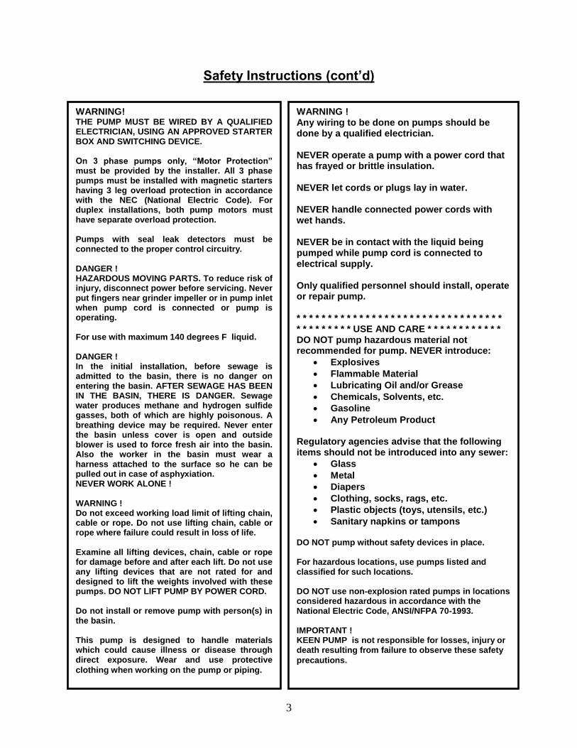
Safety Instructions (cont’d)
WARNING! THE PUMP MUST BE WIRED BY A QUALIFIED ELECTRICIAN, USING AN APPROVED STARTER BOX AND SWITCHING DEVICE. On 3 phase pumps only, “Motor Protection” must be provided by the installer. All 3 phase pumps must be installed with magnetic starters having 3 leg overload protection in accordance with the NEC (National Electric Code). For duplex installations, both pump motors must have separate overload protection. Pumps with seal leak detectors must be connected to the proper control circuitry. DANGER ! HAZARDOUS MOVING PARTS. To reduce risk of injury, disconnect power before servicing. Never put fingers near grinder impeller or in pump inlet when pump cord is connected or pump is operating. For use with maximum 140 degrees F liquid. DANGER ! In the initial installation, before sewage is admitted to the basin, there is no danger on entering the basin. AFTER SEWAGE HAS BEEN IN THE BASIN, THERE IS DANGER. Sewage water produces methane and hydrogen sulfide gasses, both of which are highly poisonous. A breathing device may be required. Never enter the basin unless cover is open and outside blower is used to force fresh air into the basin. Also the worker in the basin must wear a harness attached to the surface so he can be pulled out in case of asphyxiation. NEVER WORK ALONE ! WARNING ! Do not exceed working load limit of lifting chain, cable or rope. Do not use lifting chain, cable or rope where failure could result in loss of life. Examine all lifting devices, chain, cable or rope for damage before and after each lift. Do not use any lifting devices that are not rated for and designed to lift the weights involved with these pumps. DO NOT LIFT PUMP BY POWER CORD. Do not install or remove pump with person(s) in the basin. This pump is designed to handle materials which could cause illness or disease through direct exposure. Wear and use protective
clothing when working on the pump or piping.
WARNING ! Any wiring to be done on pumps should be done by a qualified electrician. NEVER operate a pump with a power cord that has frayed or brittle insulation. NEVER let cords or plugs lay in water. NEVER handle connected power cords with wet hands. NEVER be in contact with the liquid being pumped while pump cord is connected to electrical supply. Only qualified personnel should install, operate or repair pump. * * * * * * * * * * * * * * * * * * * * * * * * * * * * * * * * * * * * * * * * * * USE AND CARE * * * * * * * * * * * * DO NOT pump hazardous material not recommended for pump. NEVER introduce:
Explosives
Flammable Material
Lubricating Oil and/or Grease
Chemicals, Solvents, etc.
Gasoline
Any Petroleum Product Regulatory agencies advise that the following items should not be introduced into any sewer:
Glass
Metal
Diapers
Clothing, socks, rags, etc.
Plastic objects (toys, utensils, etc.)
Sanitary napkins or tampons DO NOT pump without safety devices in place. For hazardous locations, use pumps listed and classified for such locations. DO NOT use non-explosion rated pumps in locations considered hazardous in accordance with the National Electric Code, ANSI/NFPA 70-1993. IMPORTANT ! KEEN PUMP is not responsible for losses, injury or death resulting from failure to observe these safety
precautions.
4
BASIN HANDLING Although the exterior surfaces of our fiberglass reinforced plastic (FRP) sump and sewage basins are designed to
withstand normal handling, they can be damaged during transportation and installation. Basins must not be dropped,
dragged, or handled with sharp objects and with the exception of the minimal movement involved in a visual
inspection, should not be rolled.
If the basin or its shell is damaged, installation should be suspended until Keen Pump Co. or its agent can make a
determination of the extent of damage. Any repairs must be first authorized in writing by Keen Pump Co. and then
be done in accordance with Keen Pump Co. instructions.
UNLOADING, LIFTING, AND LOWERING
The proper way of moving a basin is by lifting it, using chains or cables with the optional lifting lugs (not more than
30* included angle) or by using a non-marring sling around the basin. Before any attempt is made to move a basin, it
should be established that all of the equipment and accessories have sufficient capacity and reach to lift and lower
the basins without dragging and/or dropping. Basins should be maneuvered with guide ropes attached to the sides.
WARNING !! Under NO circumstances are the use of chains or cables around the basin shell
permitted.
STORAGE
Basins should be stored in a secure, controlled area where the potential for accidental damage or vandalism will be
minimized. The storage area should be free from sharp objects, rocks and any other foreign solutions or materials
that could cause damage to the basins. Chock the basins until they are needed for installation and if windy
conditions are possible, secure the basins with non-marring restraints of a size and number adequate for securing the
basin.
PRE-INSTALLATION INSPECTION
Basins, vales, equipment, and piping materials should be physically and visually inspected before installation.
Adherence to the project’s specifications should also be confirmed before installation. If the basin or any of its
internal components are damaged, installation should be suspended until a determination of the extent of damage
can be made by Keen Pump Co. or its agent. Any repairs must be first authorized in writing by Keen Pump Co. and
then be done in accordance with Keen Pump Co. instructions.
EXCAVATION The excavation should provide adequate space for the basin, piping, and other buried equipment and for the
replacement and compaction of backfill materials particularly around the basin walls. The size, shape and wall slope
of the excavation should be determined by soil conditions, depth of excavation, shoring requirements, and if workers
are required to enter the excavation, safety considerations and federal, sate, county, and municipal regulations.
WARNING !! Locate all overhead and underground utilities before excavating
LOCATION OF EXCAVATING
Excavation for an underground basin should be made with due care to avoid undermining foundations of existing
structures and contact with underground utilities. In the absence of building codes or regulations, maintain a
minimum distance of five feet plus a slope or 45* from the bottom of the compacted sub-base to the bottom of the
adjacent structures, foundations, footings, and property lines (as shown in the attached illustration). Additional
distances may be required to assure that any loading carried or created by the foundations and supports cannot be
transferred to the basins.
HANDLING OF EXCAVATED MATERIALS
Excavated materials, which cannot be removed from the jobsite, should be carefully stored as far from the edge of
the basin excavation as possible. Unless approved for use as backfill, excavation materials should be securely stored
separate from the approved backfill materials.
5
WORK AREA SAFETY
Safe installation procedures shall be the sole responsibility of the basin installer. Work safety requirements are
defined in U.S. Department of Labor 29 CFR part 1926, subpart P, Excavations.
BACKFILLING Careful selection, placement, and compaction of approved backfill material is critical to a successful basin
installation. Among the common problems associated with basin leaks and premature failures are:
Use of incorrect backfill material
Inadequate or improper placement or compaction
Rocks, clods, or debris left in the excavation or basin
Voids under or around the perimeter of the basin
Failure to prevent the migration of backfill materials
PLACEMENT OF BASIN
The bottom of the basin excavation should be covered with suitably with graded, leveled, and compacted backfill
material to a depth of at least 12 inches (compacted sub-base). If a concrete hold-down/anti-flotation pad is required,
this bedding can be reduced to a depth of at least 6 inches. The carefully lower the basin into the excavation and
centered on the compacted backfill or concrete pad (see attached).
WARNING !! Placement of a basin on a concrete pad or compacted sub-base smaller than the
total basin bottom area or on intermediate supports (saddles) will cause uneven distribution of
loads. This may contribute to structural failure, and is never permitted.
BACKFILL MATERIAL
Backfill material should be clean, well granulated, free flowing, non-corrosive, and inert. It should be free of ice,
snow, debris, rock, or organic material, all of which could damage the tank and interfere with the compaction of the
backfill material. The largest particles should not be larger than 3/4”. Not more than 3% (by weight) should pass
through a # 8 sieve, and the backfill material should conform to ASTM C-33, Paragraph 9.1 requirements. Approved
backfill materials include:
Pea Gravel, naturally rounded particles with a minimum diameter of 1/8” and a maximum diameter of 3/4”.
Crushed rock, washed and free-flowing angular particles between 1/8” and 1/2” in size.
PLACEMENT AND COMPACTION OF BACKFILL
Compaction of backfill materials should be adequate to ensure the support of the tank, and to prevent movement or
settlement. Backfill materials should be placed in 12” lifts and compacted to a minimum soil modulus of 700 pounds
per square inch (psi)
SUPPORTING PIPING, EQUIPMENT AND ACCESSORIES
Support for piping, equipment and other accessories must be provided during backfilling. Using the basin to support
piping, equipment, cribbing, bracing, or blocking is never permitted. During backfilling, temporary supporting
materials must be carefully installed and removed to prevent damage to the basin, piping, or equipment.
WARNING !! Using the basin to support any loading carried or created by piping, equipment,
cribbing, bracing, or blocking is never permitted.
ANCHORAGE When basin installations are located in areas subject to high water tables or flooding, provisions should be made to
prevent the basins, either empty or filled, from floating. The buoyancy force to be offset is determined primarily by
the volume of the basin. The principle offsetting factors include:
Backfill materials
Concrete hold-down pad
Friction between the tank, backfill materials and the surrounding soil
6
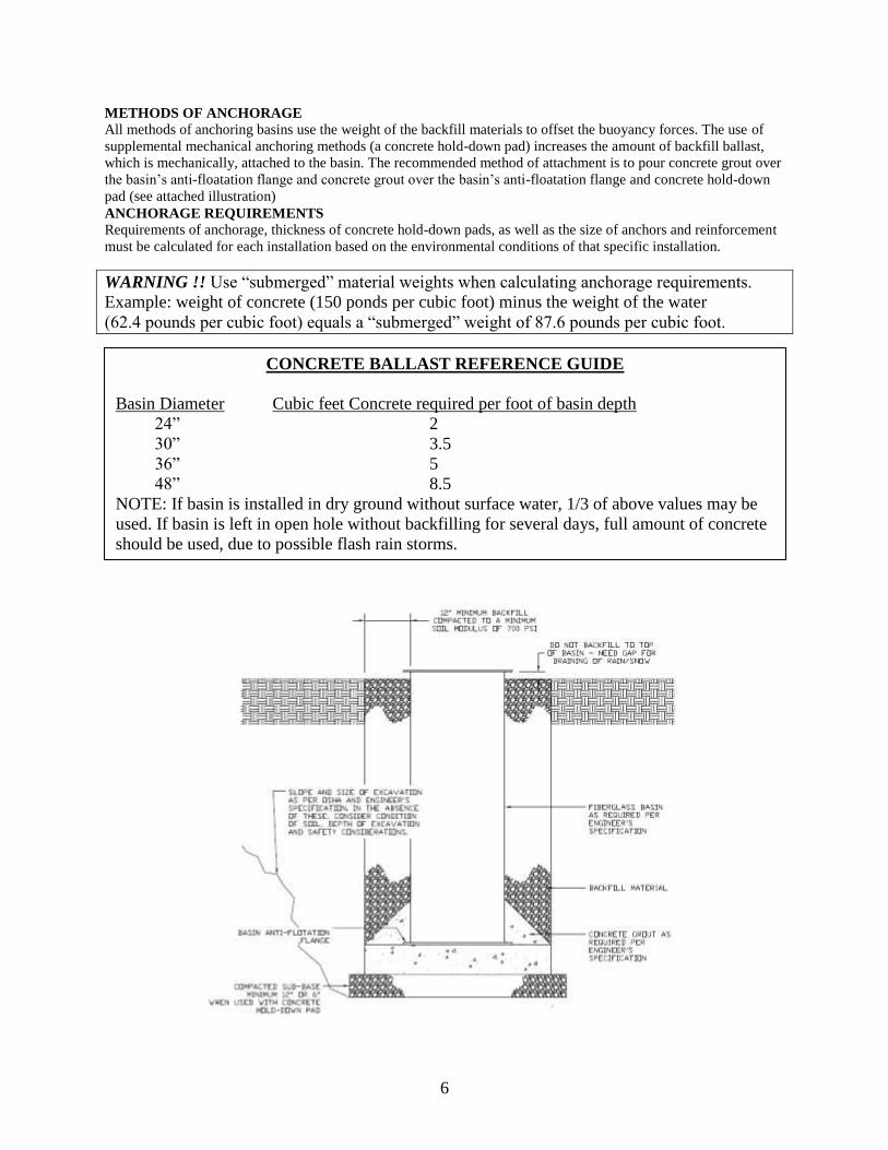
METHODS OF ANCHORAGE
All methods of anchoring basins use the weight of the backfill materials to offset the buoyancy forces. The use of
supplemental mechanical anchoring methods (a concrete hold-down pad) increases the amount of backfill ballast,
which is mechanically, attached to the basin. The recommended method of attachment is to pour concrete grout over
the basin’s anti-floatation flange and concrete grout over the basin’s anti-floatation flange and concrete hold-down
pad (see attached illustration)
ANCHORAGE REQUIREMENTS
Requirements of anchorage, thickness of concrete hold-down pads, as well as the size of anchors and reinforcement
must be calculated for each installation based on the environmental conditions of that specific installation.
WARNING !! Use “submerged” material weights when calculating anchorage requirements.
Example: weight of concrete (150 ponds per cubic foot) minus the weight of the water
(62.4 pounds per cubic foot) equals a “submerged” weight of 87.6 pounds per cubic foot.
CONCRETE BALLAST REFERENCE GUIDE
Basin Diameter Cubic feet Concrete required per foot of basin depth
24” 2
30” 3.5
36” 5
48” 8.5
NOTE: If basin is installed in dry ground without surface water, 1/3 of above values may be
used. If basin is left in open hole without backfilling for several days, full amount of concrete
should be used, due to possible flash rain storms.
7
SPECIFICATIONS For fiberglass basin package:
NOTE: Pump, lift-out check valve, floats, inlet fitting and control panel are
shipped separately.
BASIN – Fiberglass construction w/ cover flange and bottom anti-flotation collar
COVER – Solid Fiberglass, or aluminum with access hatch
DISCHARGE PIPE – 1-1/4” PVC, Schedule 80, or as req’d.
DISCHARGE HUB – 1-1/4” NPT SST (Simplex), 1-1/4”, 1-1/2” or 1-1/2”, 2”NPT SST (Duplex)
RAIL SYSTEM – Keen Pump KL1 or KL1-CV (Check valve), Cast iron, painted
KL1-CV includes ball check valve – Qty. 2 req’d for duplex
RAIL BRACKETS – Upper support and liftout yoke SST
LIFTING APPARATUS - 3/16” Stainless steel chain w/ ¼” shackles
SHUT-OFF VALVE – 1-1/4” Ball Valve, PVC, True Union, Blocked, or 1-1/4” Gate valve, brass
INLET FITTING – 4” or 6” Adaptaflex hub (Sch. 40 Pipe), or as req’d.
JUNCTION BOX – Fiberglass box designed to NEMA 6P standard, includes cord fittings and inlet hub
CONDUIT HUB – 1-1/2” or 2” NPT Plastic
LEVEL CONTROLS – Narrow angle, control duty, mercury, normally open floats, or as req’d.
LEVEL CONTROL BRACKET – SST w/ plastic cord bushing
HARDWARE – 300 Series SST
STEPS TO INSTALL A KEEN FACTORY-BUILT BASIN PACKAGE
1. BASIN INSTALLATION: The basin is supplied with a standard inlet fitting for
connecting a schedule 40 plastic pipe (4.50” OD) incoming sewer (from house). Other
inlet types or sizes are optional. Please confirm that you have the pipe that matches the
inlet fitting before continuing.
2. AFTER EXCAVATING the hole for basin (per above instructions), the basin should be
plumb. Fill the basin with water to the invert (bottom of inlet pipe) to prevent basin from
shifting as concrete is being poured for ballast.
3. INLET PIPE: If installing the standard 4” inlet fitting, a standard 5” diameter pilot
hole-saw is required. If installing the 6” inlet fitting, a standard 7” diameter pilot hole-
saw is required. The minimum invert level (bottom of inlet pipe) required is 36” (3’-0”)
from bottom of basin. After drilling hole, remove rough edges of fiberglass – coat with
resin if available. Place inlet fitting through hole on outside wall of basin. Cut and

8
chamfer inlet pipe. Lubricate pipe and inlet fitting with soapy water. Insert inlet pipe into
fitting and protrude through basin wall. Pipe must protrude a minimum of 1” past inlet
fitting.
4. DISCHARGE PIPE: The use of schedule 40 pvc, HDPE (DR), and SDR pipe is
recommended. The standard Keen flange connection is 1-1/4” NPT for all simplex basin
packages, and 1-1/2” NPT for all duplex basin packages. IT IS STRONGLY
RECOMMENDED TO INSTALL A REDUNDANT CHECK VALVE between the
Keen basin and the street main on all installations.
5. BACKFILL using the previous illustration and instructions.
6. VENTING: It is unnecessary to vent a Keen Pump basin package as long as the house
vent stack is properly vented to the rooftop. A separate 2” mushroom vent is optional and
can be included to attach to basin cover if required.
7. INSTALL PUMP AND LIFTOUT: (See illustration to attach lift-out to pump volute).
Remove (2) two 5/16” bolts from pump volute adapter. Separate threaded pump adapter
from volute. Install adapter onto 1-1/4” pipe/lift-out assembly. Reinstall adapter and pipe
assembly onto pump. Attach lift cable/chain to pump lift bail. Pump is now ready to
install into basin.
8. POSITION PUMP so the guide rails are located in the slots of the guide plate. Slowly
lower the pump down the guide rails to the base. Retain pump cables so they do not drop
into the basin. The tapered arms in the base will automatically seal and pull the mating
faces together when lowered into place.
9. FLOATS: A typical simplex system with control panel will consist of (3) three float
control switches (Off, On and High Water Alarm). A typical duplex system will consist
of (4) four float control switches (Off, Lead Pump On, Lag Pump On, and High Water
Alarm). A system with an automatic pump will be equipped with (2) two float switches
(On-Off, and High Water Alarm). All floats will be attached to float bracket, which is
installed near the top of the basin. Each float cord will have a cord bushing that fits into
the float bracket. The recommended float settings are as follows for KEEN 1hp pump
9
models: (Note – all settings are activation levels). NO PUMP ON/OFF FLOAT
SWITCH SHOULD BE SET THAT WILL EXCEED 10 STARTS PER HOUR PER
PUMP.
(3) FLOAT OPERATION SIMPLEX: - 15” from basin bottom to “OFF” setting – KPCG (Minimum)
- 27” from basin bottom to “ON” setting – KPCG (Min.)
- 33” from basin bottom to “HWA” setting – KPCG (Min.)
(2) FLOAT OPERATION SIMPLEX: - 15” from basin bottom to “ON-OFF” setting – KPCG (Min.)
- 33” from basin bottom to “HWA” setting – KPCG (Min.)
(4) FLOAT OPERATION DUPLEX: - 15” from basin bottom to “OFF” setting – KPCG (Min.)
- 27” from basin bottom to “LEAD PUMP ON” setting – KPCG (Min.)
- 33” from basin bottom to “LAG PUMP ON” setting – KPCG (Min.)
- 35” from basin bottom to “HWA” setting – KPCG (Min.)
10. JUNCTION BOX/ELECTRICAL CONNECTION: Connect level control and pump
power cords to junction box. Make certain that all compression fittings are tight. Install
control panel. Run wires to control panel through conduit and connect cords coming into
control panel. Mark or trace each incoming wire so that it can be connected to proper
cord.
STARTING PUMPS
1. Open shutoff valves on discharge piping.
2. Set pump switches at control panel to “auto” position and turn on power. Fill basin with
water until controls start pump. Allow pump to operate until level drops, stopping pump.
3. If system is duplex, turn both pump switches to “off” and fill basin above upper control.
Turn both pump switches to “auto” position. Both pumps should run and pump basin
down to lower control.
4. Leave both switches in “auto” position and pump is ready for automatic operation.
5. A small weep hole may need to be drilled in the pump volute case or discharge pipe to
prevent air-lock, so some water will flow from this hole when pump is operating.
TROUBLESHOOTING
1. Pump runs but does not deliver water.
a. May be air-locked. Lift pump and reseat onto discharge base.
b. Discharge shutoff valve may be closed.
c. If pump is 3-phase, may be running in wrong direction. Pump should be checked
before installing in basin for proper rotation. ROTATION: Counterclockwise
when looking into pump inlet.
CAUTION: KEEP HANDS AND FINGERS AWAY FROM GRINDER IMPELLER
WHEN MAKING THIS CHECK. If 3-phase rotation is wrong, interchange any two
line leads at the control panel to reverse motor. CAUTION: BE SURE CONNECTED
POWER AGREES WITH DATA ON PUMP NAMEPLATE.
2. Liftout base flange leaks

10
a. O-ring or gasket cut
b. Trash may be caught under flange. Lift out and reseat. It may be necessary to run
pump lifted out of base elbow to flush away trash.
3. Proper setting of level controls. Controls should be set so that pump stops when level is
minimum 6 inches above pump inlet. If controls are set too high, trash and grease may
accumulate on the surface and may cause clogging.
CAUTION: NEVER WORK ON PUMPS OR CONTROLS UNLESS POWER IS
TURNED OFF. IF PUMP IS REMOTE FROM CONTROL PANEL, DISCONNECT
WIRES TO PUMPS TO BE CERTAIN POWER CANNOT BE TURNED ON. THIS
MEANS ALL WIRES INCLUDING CONTROL WIRES. NEVER PUT HANDS NEAR
GRINDER IMPELLER ON ANY RUN CHECKS.
STEPS TO INSTALL A KEEN SYSTEM IN CONCRETE BASIN
1. Clean basin bottom thoroughly before installing the rail system components.
2. Bolt discharge base elbow in place on basin bottom. NOTE: KPCG PROGRESSIVE
CAVITY PUMP TO REQUIRE 3” SPACER BETWEEN FLOOR AND BASE. See
typical layout dimensions on following pages or consult factory.
3. Install discharge piping from base elbow complete through basin wall. Cement in place.
4. Keen recommends mounting guide rails to access cover hatch frame. Mount upper rail
support onto hatch cover frame per typical layout as follows or consult factory.
5. Install ¾” or 1” guide rails. Schedule 40 stainless steel is recommended. To get proper
length, upper rail support must be installed prior to trimming rail pipes. Align rail pipes
plumb by using a level in two directions on pipe.
6. Mount level control bracket as shown on typical layout as follows. Set float control
heights per instruction above or as required by engineer. Consult factory for special
settings required.
7. If control panel is remotely mounted, attach conduit pipe through basin wall and cement
in place. See typical layout as follows for placement of conduit.
8. Be certain all inlet and discharge piping is properly connected before backfilling.
9. INSTALL PUMP AND LIFTOUT: (See illustration above to attach lift-out flange from
the Keen “KL1[CV]” to pump volute). Attach lift cable/chain to pump lift bail. Pump is
now ready to install into basin.
TYPICAL INSTALLATIONS AND DIMENSIONS ON PROCEEDING
PAGES
1. KPCG grinder pump with KL1 liftout dimensions
2. KPCG grinder pump with KL1CV liftout dimensions
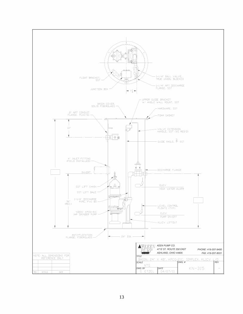
3. Fiberglass basin assembly, 24” Diameter simplex
4. Fiberglass basin assembly, 48” Diameter duplex
NOTE: CONSULT FACTORY IF DIMENSIONS OR LAYOUTS
REQUIRED ARE NOT INCLUDED WITH THIS MANUAL.
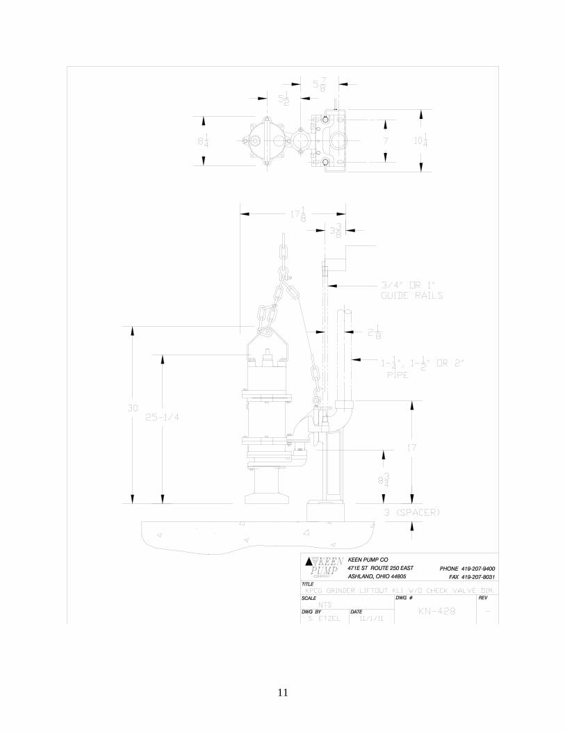
11

12
13
471E ST. ROUTE 250 EAST
ASHLAND, OHIO 44805
KEEN PUMP CO.
DATEDWG. BY
TITLE
DWG. # REV.
PHONE: 419-207-9400
FAX: 419-207-8031
SCALE

14
471E ST. ROUTE 250 EAST
ASHLAND, OHIO 44805
KEEN PUMP CO.
DATEDWG. BY
TITLE
DWG. # REV.
PHONE: 419-207-9400
FAX: 419-207-8031
SCALE

15
47
1E
S
T. R
OU
TE
250 E
AS
T
AS
HL
AN
D, O
HIO
44805
KE
EN
P
UM
P C
O.
DA
TE
DW
G. B
Y
TITL
E
DW
G. #
RE
V.
PH
ON
E: 4
19
-207-9400
FA
X: 4
19
-207-8031
SC
AL
E
P/N O&M-1HPBASINRAILS