INSTALLATION AND OPERATORS MANUAL€¦ · DSE 3110 FAULT CODES DSE 3110 ENGINE CONTROL MODULE...
24
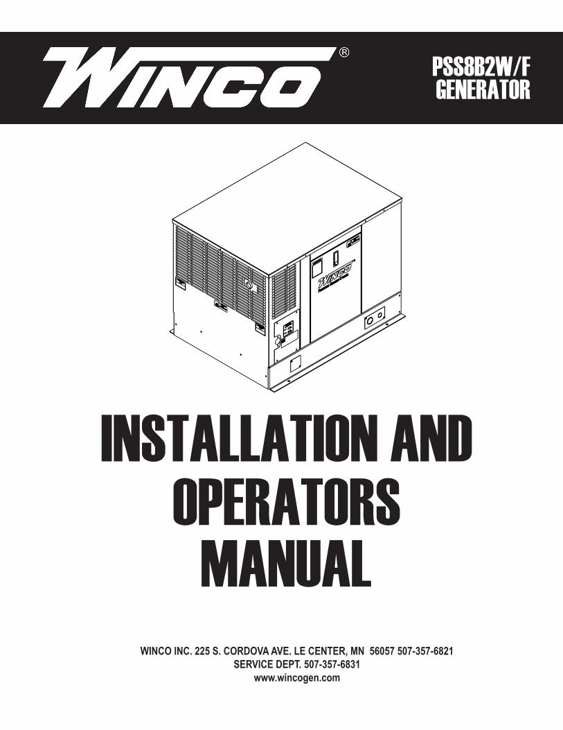
WINCO INC. 225 S. CORDOVA AVE. LE CENTER, MN 56057 507-357-6821 SERVICE DEPT. 507-357-6831 www.wincogen.com INSTALLATION AND OPERATORS PSS8B2W/F GENERATOR MANUAL
Transcript of INSTALLATION AND OPERATORS MANUAL€¦ · DSE 3110 FAULT CODES DSE 3110 ENGINE CONTROL MODULE...
WINCO INC. 225 S. CORDOVA AVE. LE CENTER, MN 56057 507-357-6821SERVICE DEPT. 507-357-6831
www.wincogen.com
INSTALLATION AND OPERATORS
PSS8B2W/F GENERATOR
MANUAL
2 REV E60706-211
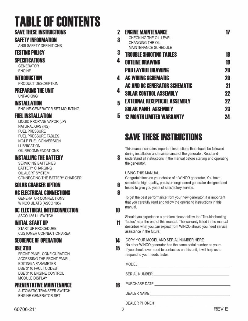
TABLE OF CONTENTSSAVE THESE INSTRUCTIONS 2SAFETY INFORMATION 3
ANSI SAFETY DEFINITIONS
TESTING POLICY 3SPECIFICATIONS 4
GENERATORENGINE
INTRODUCTION 4PRODUCT DESCRIPTION
PREPARING THE UNIT 4UNPACKING
INSTALLATION 5ENGINE-GENERATOR SET MOUNTING
FUEL INSTALLATION 5LIQUID PROPANE VAPOR (LP)NATURAL GAS (NG)FUEL PRESSUREFUEL PRESSURE TABLESNG/LP FUEL CONVERSIONLUBRICATIONOIL RECOMMENDATIONS
INSTALLING THE BATTERY 8SERVICING BATTERIESBATTERY CHARGINGOIL ALERT SYSTEMCONNECTING THE BATTERY CHARGER
SOLAR CHARGER OPTION 9AC ELECTRICAL CONNECTIONS 9
GENERATOR CONNECTIONSWINCO UL ATS (ASCO 185)
DC ELECTRICAL INTERCONNECTION 10ASCO 185 UL SWITCH
INITIAL START UP 11START UP PROCEDURECUSTOMER CONNECTION AREA
SEQUENCE OF OPERATION 14DSE 3110 15
FRONT PANEL CONFIGURATIONACCESSING THE FRONT PANELEDITING A PARAMETERDSE 3110 FAULT CODESDSE 3110 ENGINE CONTROLMODULE DISPLAY
PREVENTATIVE MAINTENANCE 16AUTOMATIC TRANSFER SWITCHENGINE-GENERATOR SET
SAVE THESE INSTRUCTIONSThis manual contains important instructions that should be followed during installation and maintenance of the generator. Read and understand all instructions in the manual before starting and operating the generator.
USING THIS MANUALCongratulations on your choice of a WINCO generator. You have selected a high-quality, precision-engineered generator designed and tested to give you years of satisfactory service.
To get the best performance from your new generator, it is important that you carefully read and follow the operating instructions in this manual.
Should you experience a problem please follow the “Troubleshooting Tables” near the end of this manual. The warranty listed in the manual describes what you can expect from WINCO should you need service assistance in the future.
COPY YOUR MODEL AND SERIAL NUMBER HERENo other WINCO generator has the same serial number as yours. If you should ever need to contact us on this unit, it will help us to respond to your needs faster.
MODEL __________________________________________________
SERIAL NUMBER _________________________________________
PURCHASE DATE _________________________________________
DEALER NAME ___________________________________________
DEALER PHONE # ________________________________________
ENGINE MAINTENANCE 17CHECKING THE OIL LEVELCHANGING THE OILMAINTENANCE SCHEDULE
TROUBLE SHOOTING TABLES 18OUTLINE DRAWING 19PAD LAYOUT DRAWING 20AC WIRING SCHEMATIC 20AC AND DC GENERATOR SCHEMATIC 21SOLAR CONTROL ASSEMBLY 22EXTERNAL RECEPTICAL ASSEMBLY 22SOLAR PANEL ASSEMBLY 2312 MONTH LIMITED WARRANTY 24
3REV E 60706-211
SAFETY INFORMATIONThis engine generator set has been designed and manufactured to allow safe, reliable performance. Poor maintenance, improper or careless use can result in potentially deadly hazards; from electrical shock, exhaust gas asphyxiation, or fire. Please read all safety instructions carefully before installation or use. Keep these instructions handy for future reference. Take special note and follow all warnings on the unit labels and in the manuals.
ANSI SAFETY DEFINITIONSDANGER:DANGER indicates an imminently hazardous situation which, if not avoided, will result in death or serious injury. This signal word is to be limited to the most extreme situations.
WARNING:WARNING indicates a potentially hazardous situation which, if not avoided, could result in death or serious injury.
CAUTION:CAUTION indicates a potentially hazardous situation which, if not avoided, may result in minor or moderate injury. It may also be used to alert against unsafe practices.
1. ELECTRICAL SHOCK -
The output voltage present in this equipment can cause fatal electric shock. This equipment must be operated by a responsible person.
A. Do not allow anyone to operate the generator without proper instruction. B. Guard against electric shock. C. Avoid contact with live terminals or receptacles. D. Use extreme care if operating this unit in rain or snow. E. Use only three-pronged grounded receptacles and extension cords. F. Be sure the unit is properly grounded to an external ground rod driven into the earth.
2. FIRE HAZARD -
Gasoline and other fuels present a hazard of possible explosion and/or fire. A. Do not refuel when the engine is running or hot. B. Keep fuel containers out of reach of children. C. Do not smoke or use open flame near the generator set or fuel tank. D. Keep a fire extinguisher nearby and know its proper use. Fire extinguishers rated ABC by NFPA are appropriate. E. Store fuel only in an approved container, and only in a well ventilated area. F. Follow local codes for closeness to combustible material.
3. DEADLY EXHAUST GAS -
Exhaust fumes from any gasoline engine contain carbon monoxide, an invisible, odorless and deadly gas that must be mixed with fresh air.
A. Operate only in well ventilated areas. B. Never operate indoors including attached garages C. Never operate the unit in such a way as to allow exhaust gases to seep back into closed rooms (i.e. through windows, walls, floors).
4. NOISE HAZARD -
Excessive noise is not only tiring, but continual exposure can lead to loss of hearing.
A. Use hearing protection when working around this equipment for long periods of time. B. Keep your neighbors in mind when using this equipment.
5. CLEANLINESS -
Keep the generator and surrounding area clean.
A. Remove all grease, ice, snow or materials that create slippery conditions around the unit. B. Remove any rags or other materials that could create a potential fire hazard. C. Carefully clean up any gas or oil spills before starting the unit.
6. SERVICING EQUIPMENT -
All service, including the installation or replacement of service parts, should be performed only by a qualified technician.
A. Use only factory approved repair parts. B. Do not work on this equipment when fatigued. C. Never remove the protective guards, covers, or receptacle panels while the engine is running. D. Use extreme caution when working on electrical components. High output voltage from this equipment can cause serious injury or death. E. Always avoid hot mufflers, exhaust manifolds, and engine parts. They can cause severe burns instantly. F. The use of the engine-generator set must comply with all national, state, and local codes.
CALIFORNIA PROPOSITION 65WARNING: This product contains crude oil, gasoline, diesel fuel and other petroleum products, Antifreeze to which can expose you to chemicals including toluene and benzene, Ethylene glycol (ingested) which are
known to the State of California to cause cancer, birth defects or other reproductive harm and developmental issues. For more information go to www.P65Warning.ca.gov.
4 REV E60706-211
SPECIFICATIONSGENERATOR
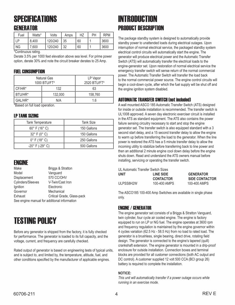
Fuel Watts* Volts Amps HZ PH RPMLP 8,400 120/240 35 60 1 3600NG 7,600 120/240 32 60 1 3600
*Continuous rating.Derate 3.5% per 1000 feet elevation above sea level. For prime power option, derate 30% and note the circuit breaker derates to 25 Amp.
FUEL CONSUMPTIONNatural Gas
1000 BTU/FT³LP Vapor
2520 BTU/FT³CF/HR* 132 63BTU/HR* 132,000 158,760GAL/HR* N/A 1.6
*Based on full load operation.
LP TANK SIZINGTank Temperature Tank Size
60° F (16° C) 150 Gallons32° F (0° C) 150 Gallons0° F (18° C) 250 Gallons
-20° F (-29° C) 500 Gallons
ENGINEMake Briggs & Stratton Model VanguardDisplacement 570 CC/OHVCylinders/Sleeves V-Twin/Cast IronIgnition ElectronicGovernor MechanicalExhaust Critical Grade, Glass-packSee engine manual for additional information
INTRODUCTIONPRODUCT DESCRIPTIONThe package standby system is designed to automatically provide standby power to unattended loads during electrical outages. Upon interruption of normal electrical service, the packaged standby system electrical control circuits will automatically start the engine. The generator will produce electrical power and the Automatic Transfer Switch (ATS) will automatically transfer the electrical loads to theengine-generator set. Upon restoration of normal electrical service the emergency transfer switch will sense return of the normal commercial power. The Automatic Transfer Switch will transfer the load backto the normal commercial power source. The engine control circuits will begin a cool-down cycle, after which the fuel supply will be shut off and the engine ignition system disabled.
AUTOMATIC TRANSFER SWITCH (not included)A wall mounted ASCO 185 Automatic Transfer Switch (ATS) designed for inside or outside installation is recommended. The transfer switch is UL1008 approved. A seven day electronic exerciser circuit is installedin the ATS as standard equipment. The ATS also contains the power failure sensing circuitry necessary to start and stop the engine generator set. The transfer switch is also equipped standard with a 3 second start delay, and a 15 second transfer delay to allow the engine to warm up before transferring the load to the generator. When the line power is restored the ATS has a 5 minute transfer delay to allow the incoming utility to stabilize before transferring back to line power and then an additional 2 minute engine cool down delay before the engine shuts down. Read and understand the ATS owners manual before installing, servicing or operating the transfer switch.
UL Automatic Transfer Switch Sizes UNIT LINE SIDE GENERATOR CONTACTOR SIDE CONTACTORULPSS8H2W 100-400 AMPS 100-400 AMPS
The ASCO185 100-400 Amp Switches are available in single phase only.
ENGINE / GENERATORThe engine generator set consists of a Briggs & Stratton Vanguard, twin cylinder, four cycle air cooled engine. The engine is factory equipped to run on LP or NG fuel. The engine operates at 3600 rpm and frequency regulation is maintained by the engine governor within 4 cycles variation (62.5 Hz - 58.5 Hz) from no load to rated load. The generator is a brushless, single bearing, direct drive, rotating field design. The generator is connected to the engine’s tapered (quill) crankshaft extension. The engine generator is mounted in a drip-proof enclosure for outside installation. Connection boxes and terminal blocks are provided for all customer connections (both AC output and DC control). A customer supplied 12 volt 500 CCA (BCI group 26) battery is required to complete the installation.
NOTICE: This unit will automatically transfer if a power outage occurs while running in an exercise mode.
TESTING POLICYBefore any generator is shipped from the factory, it is fully checked for performance. The generator is loaded to its full capacity, and the voltage, current, and frequency are carefully checked.
Rated output of generator is based on engineering tests of typical units, and is subject to, and limited by, the temperature, altitude, fuel, and other conditions specified by the manufacturer of applicable engines.
5REV E 60706-211
PREPARING THE UNITUNPACKINGCAUTION: EQUIPMENT DAMAGEWhen you unpack your new generator, be sure to remove all of the information sheets and manual from the carton.
1. As you receive your unit, it is critical to check it for any damage. If any damage is noted, it is always easiest to refuse the shipment and let WINCO take care of the freight claim. If you sign for the unit, the transfer of the ownership requires that you file the freight claim
2. Before proceeding with the preparations of your new generator for operation, take a couple of minutes to ensure the unit you have received is the correct model and review the specification pages in this manual to ensure that this unit meets your job requirements.
CAUTION: These units are shipped with oil. Be sure to check oil levels before operating. See engine manufacturer’s instruction manual for recommended oil requirements before initial starting.
INSTALLATIONWARNING: Before proceeding with installation, be sure the operation selector switch is in the stop position.
These engine generator sets are designed to be mounted on a pad outdoors only. The transfer switch is mounted next to your electrical entrance or distribution panel inside or outside the building. Consult a qualified, licensed electrician or contractor to install and wire the transfer switch. The installation must comply with all national, state and local codes. Before beginning the installation process check the rating of the generator set and its transfer switch rating. Be certain they can handle the intended load and are compatible with the entrance voltage, phase and current ratings. Plans for installation should be prepared with proper attention to mechanical and electrical engineering detail to assure a satisfactory system installation. The information in this manual is offered only as a guide to finalizing your installation plans.
ENGINE-GENERATOR SET MOUNTINGWARNING: PERSONAL INJURY:The enclosures on these units can become very hot adjacent to the exhaust areas. Special care must be taken when installing these units to insure that the risk of contact by people is minimized.
The unit’s main frame should be bolted to a pad that meets local code.
Various materials, including concrete and composites, are acceptable as long as they are structurally sound supporting the weight of the unit and preventing movement during operation. The mounting holes on the base of this unit is 0.563” in diameter. The engine-generator is mounted on a sub-frame which is isolated with special shock mounts on the main frame. This allows the engine-generator to vibrate without affecting the control panel on the main frame. Do not install any shock mounts between the base frame and the pad. Engine vibration will be transmitted to the control panel causing erroneous start/stop cycles and premature control failure.These units should be mounted a minimum of 24” from a structure. This will allow for ample room to maintain and work on the generator set.Units must be installed in accordance with all local, state, and national codes. Consult your local agency for specific requirements.
FUEL INSTALLATIONThe fuel supply should be as close as possible to the engine. This will reduce the installation cost of fuel runs. The information in this manual is offered to assist you in providing the proper fuel for your engine. However, this information is only provided to inform you of the engine’s requirements and assist in making you aware of the decisions you must make. In no case should the instructions and information provided be interpreted to conflict with any local, state or national codes. If in doubt, always consult your local fire marshal, gas supplier or building inspector.
WARNING: FIRE HAZARD:All fuel runs should be installed by a licensed fuel supplier.
To connect the fuel line to the generator set you will connect your incoming fuel line to the 3/4 inch NPT fitting located on the left side of the engine-generator set. This fitting is shipped with a plastic plug installed to insure the fuel system stays clean. For all vapor fuel systems the delivery pressure of the fuel to the fuel solenoid on the unit must be four to six ounces psi (per square inch) or 7 to 11 inchesW.C. (water column). These fuel pressures are critical; failure to provide the proper pressure can cause many problems ranging from a unit that will not start to causing damage to the fuel system.
These units are normally tested on Natural Gas and will have a tag hanging on the fuel hose indicating on what fuel your unit was factory tested. If you are running on LP or have to change fuel types at any time, see information on page 8 on NG/LP CONVERSION. INSTALLING THE FUEL LINE
NOTICE: The engine generator sets are properly adjusted before they leave the factory. A tag is attached to the unit that specifies the fuel, natural gas (NG) or propane vapor (LP) that the unit was set up and tested on.
NATURAL GAS or LP VAPOR PIPE SIZESize of pipe normally required for generators operating on natural gas or LP vapor. Unit location will determine the size of fuel line that is required to supply the engine with a constant fuel pressure and volume.
6 REV E60706-211
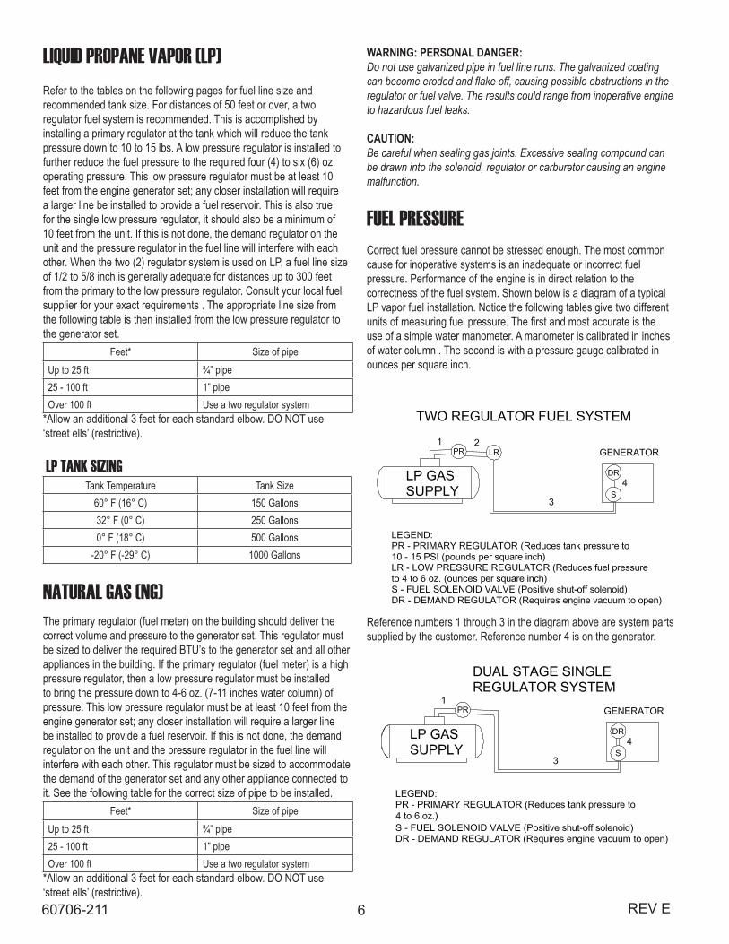
LIQUID PROPANE VAPOR (LP)Refer to the tables on the following pages for fuel line size and recommended tank size. For distances of 50 feet or over, a two regulator fuel system is recommended. This is accomplished by installing a primary regulator at the tank which will reduce the tank pressure down to 10 to 15 lbs. A low pressure regulator is installed to further reduce the fuel pressure to the required four (4) to six (6) oz. operating pressure. This low pressure regulator must be at least 10 feet from the engine generator set; any closer installation will require a larger line be installed to provide a fuel reservoir. This is also true for the single low pressure regulator, it should also be a minimum of 10 feet from the unit. If this is not done, the demand regulator on the unit and the pressure regulator in the fuel line will interfere with each other. When the two (2) regulator system is used on LP, a fuel line size of 1/2 to 5/8 inch is generally adequate for distances up to 300 feet from the primary to the low pressure regulator. Consult your local fuel supplier for your exact requirements . The appropriate line size from the following table is then installed from the low pressure regulator to the generator set.
Feet* Size of pipeUp to 25 ft ¾” pipe25 - 100 ft 1” pipeOver 100 ft Use a two regulator system
*Allow an additional 3 feet for each standard elbow. DO NOT use ‘street ells’ (restrictive).
LP TANK SIZINGTank Temperature Tank Size
60° F (16° C) 150 Gallons32° F (0° C) 250 Gallons0° F (18° C) 500 Gallons
-20° F (-29° C) 1000 Gallons
NATURAL GAS (NG)The primary regulator (fuel meter) on the building should deliver the correct volume and pressure to the generator set. This regulator must be sized to deliver the required BTU’s to the generator set and all other appliances in the building. If the primary regulator (fuel meter) is a high pressure regulator, then a low pressure regulator must be installed to bring the pressure down to 4-6 oz. (7-11 inches water column) of pressure. This low pressure regulator must be at least 10 feet from the engine generator set; any closer installation will require a larger line be installed to provide a fuel reservoir. If this is not done, the demand regulator on the unit and the pressure regulator in the fuel line will interfere with each other. This regulator must be sized to accommodate the demand of the generator set and any other appliance connected to it. See the following table for the correct size of pipe to be installed.
Feet* Size of pipeUp to 25 ft ¾” pipe25 - 100 ft 1” pipeOver 100 ft Use a two regulator system
*Allow an additional 3 feet for each standard elbow. DO NOT use ‘street ells’ (restrictive).
WARNING: PERSONAL DANGER: Do not use galvanized pipe in fuel line runs. The galvanized coating can become eroded and flake off, causing possible obstructions in the regulator or fuel valve. The results could range from inoperative engine to hazardous fuel leaks.
CAUTION:Be careful when sealing gas joints. Excessive sealing compound can be drawn into the solenoid, regulator or carburetor causing an engine malfunction.
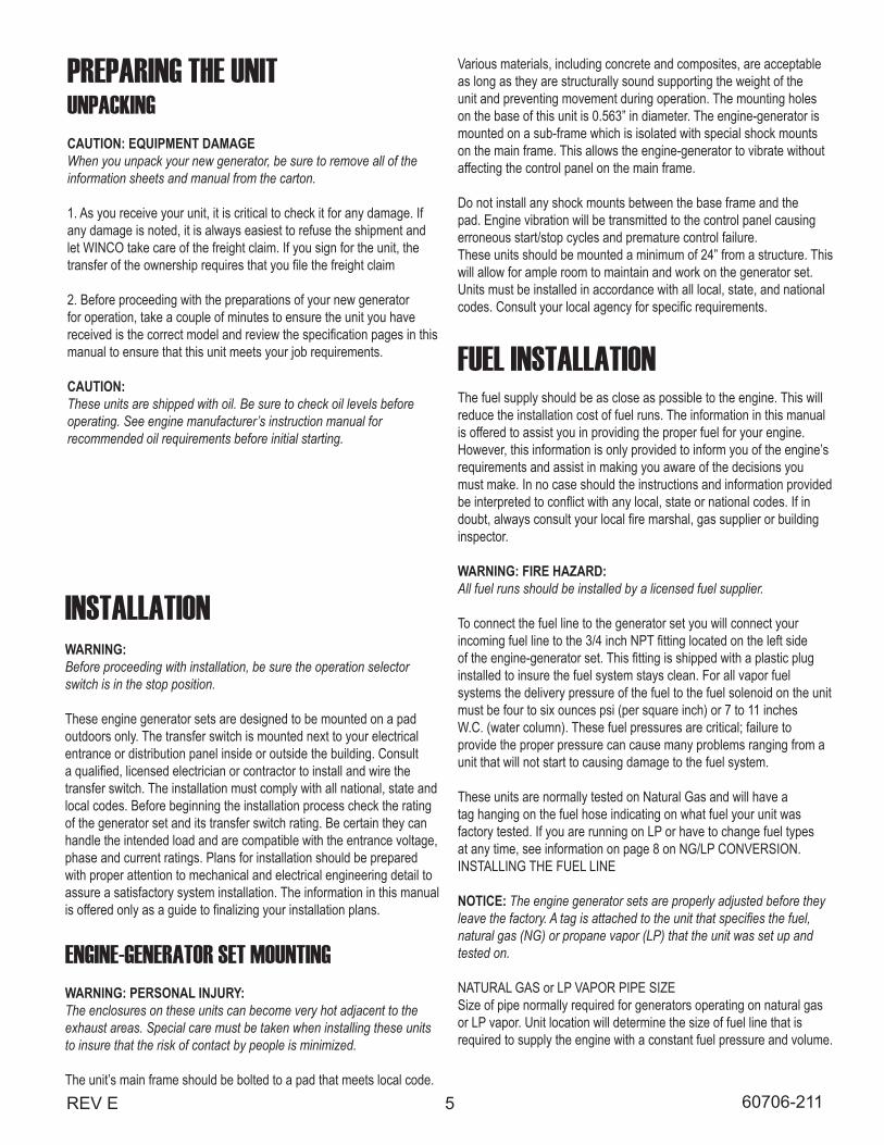
FUEL PRESSURECorrect fuel pressure cannot be stressed enough. The most common cause for inoperative systems is an inadequate or incorrect fuel pressure. Performance of the engine is in direct relation to the correctness of the fuel system. Shown below is a diagram of a typical LP vapor fuel installation. Notice the following tables give two different units of measuring fuel pressure. The first and most accurate is the use of a simple water manometer. A manometer is calibrated in inches of water column . The second is with a pressure gauge calibrated in ounces per square inch.
Reference numbers 1 through 3 in the diagram above are system parts supplied by the customer. Reference number 4 is on the generator.
7REV E 60706-211
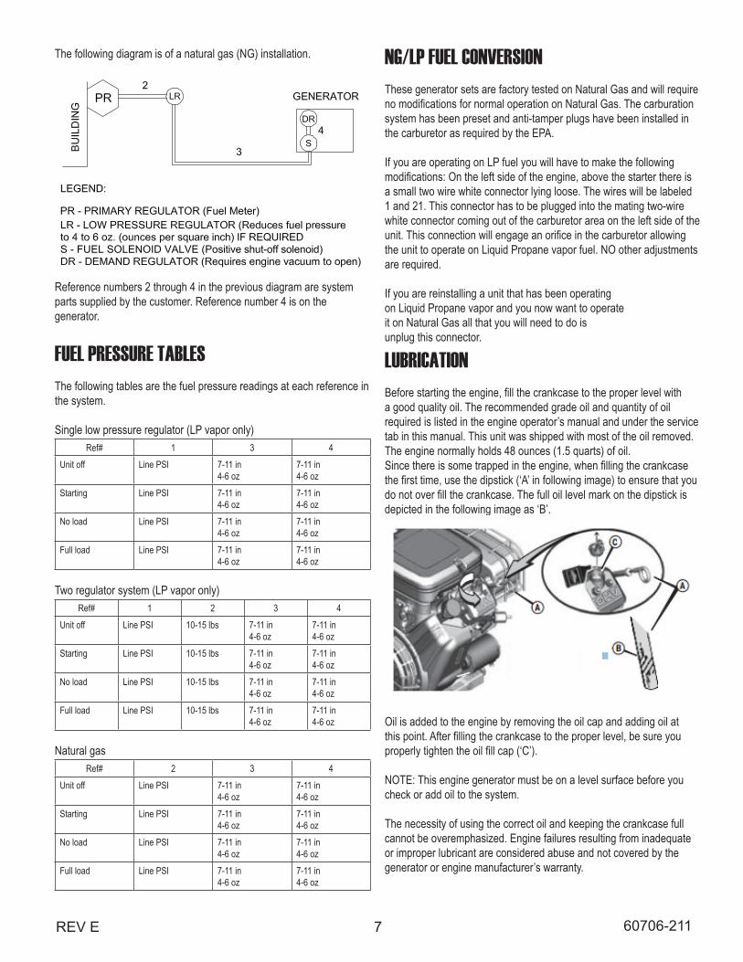
The following diagram is of a natural gas (NG) installation.
Reference numbers 2 through 4 in the previous diagram are system parts supplied by the customer. Reference number 4 is on the generator.
FUEL PRESSURE TABLESThe following tables are the fuel pressure readings at each reference in the system.
Single low pressure regulator (LP vapor only)Ref# 1 3 4
Unit off Line PSI 7-11 in4-6 oz
7-11 in 4-6 oz
Starting Line PSI 7-11 in4-6 oz
7-11 in4-6 oz
No load Line PSI 7-11 in4-6 oz
7-11 in4-6 oz
Full load Line PSI 7-11 in4-6 oz
7-11 in4-6 oz
Two regulator system (LP vapor only)Ref# 1 2 3 4
Unit off Line PSI 10-15 lbs 7-11 in4-6 oz
7-11 in4-6 oz
Starting Line PSI 10-15 lbs 7-11 in4-6 oz
7-11 in4-6 oz
No load Line PSI 10-15 lbs 7-11 in4-6 oz
7-11 in4-6 oz
Full load Line PSI 10-15 lbs 7-11 in4-6 oz
7-11 in4-6 oz
Natural gasRef# 2 3 4
Unit off Line PSI 7-11 in4-6 oz
7-11 in 4-6 oz
Starting Line PSI 7-11 in4-6 oz
7-11 in4-6 oz
No load Line PSI 7-11 in4-6 oz
7-11 in4-6 oz
Full load Line PSI 7-11 in4-6 oz
7-11 in4-6 oz
NG/LP FUEL CONVERSIONThese generator sets are factory tested on Natural Gas and will require no modifications for normal operation on Natural Gas. The carburation system has been preset and anti-tamper plugs have been installed in the carburetor as required by the EPA.
If you are operating on LP fuel you will have to make the following modifications: On the left side of the engine, above the starter there is a small two wire white connector lying loose. The wires will be labeled 1 and 21. This connector has to be plugged into the mating two-wire white connector coming out of the carburetor area on the left side of the unit. This connection will engage an orifice in the carburetor allowing the unit to operate on Liquid Propane vapor fuel. NO other adjustments are required.
If you are reinstalling a unit that has been operatingon Liquid Propane vapor and you now want to operateit on Natural Gas all that you will need to do isunplug this connector.
LUBRICATIONBefore starting the engine, fill the crankcase to the proper level witha good quality oil. The recommended grade oil and quantity of oilrequired is listed in the engine operator’s manual and under the servicetab in this manual. This unit was shipped with most of the oil removed.The engine normally holds 48 ounces (1.5 quarts) of oil.Since there is some trapped in the engine, when filling the crankcasethe first time, use the dipstick (‘A’ in following image) to ensure that youdo not over fill the crankcase. The full oil level mark on the dipstick isdepicted in the following image as ‘B’.
Oil is added to the engine by removing the oil cap and adding oil atthis point. After filling the crankcase to the proper level, be sure youproperly tighten the oil fill cap (‘C’).
NOTE: This engine generator must be on a level surface before youcheck or add oil to the system.
The necessity of using the correct oil and keeping the crankcase fullcannot be overemphasized. Engine failures resulting from inadequateor improper lubricant are considered abuse and not covered by thegenerator or engine manufacturer’s warranty.
8 REV E60706-211
INSTALLING THE BATTERYCAUTION:In the following battery installation procedure, check to be sure the selector switch remains in the ‘off’ position. This should be your last step before initial start-up.
A customer supplied twelve-volt battery is required to complete the installation. Installation of the highest CCA rated battery, within the correct BCI group (size), will increase cold weather starting performance. Gel batteries should not be used with the battery tender installed in the generator enclosure.
Voltage BCI Group MIN. CCA Rating 12 26 500
Installation and servicing of batteries must be performed or supervised only by persons knowledgeable of batteries and the required precautions. Keep unauthorized persons away from batteries. When installing or replacing batteries, use the proper group/size starting battery. The battery should be a maintenance free lead acid design. Deep cycle batteries will not work for this application.
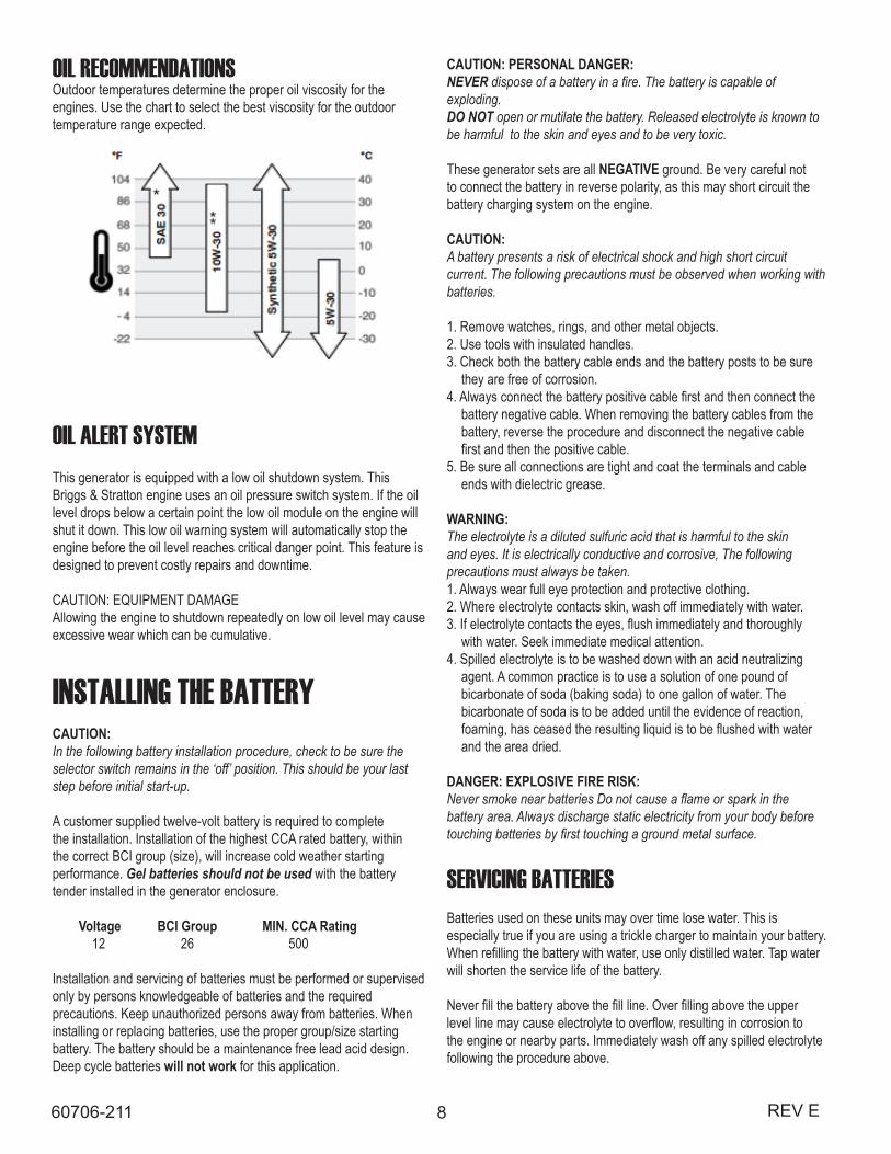
OIL RECOMMENDATIONSOutdoor temperatures determine the proper oil viscosity for theengines. Use the chart to select the best viscosity for the outdoortemperature range expected.
OIL ALERT SYSTEMThis generator is equipped with a low oil shutdown system. ThisBriggs & Stratton engine uses an oil pressure switch system. If the oillevel drops below a certain point the low oil module on the engine willshut it down. This low oil warning system will automatically stop theengine before the oil level reaches critical danger point. This feature isdesigned to prevent costly repairs and downtime.
CAUTION: EQUIPMENT DAMAGEAllowing the engine to shutdown repeatedly on low oil level may causeexcessive wear which can be cumulative.
CAUTION: PERSONAL DANGER:NEVER dispose of a battery in a fire. The battery is capable of exploding.DO NOT open or mutilate the battery. Released electrolyte is known to be harmful to the skin and eyes and to be very toxic.
These generator sets are all NEGATIVE ground. Be very careful not to connect the battery in reverse polarity, as this may short circuit the battery charging system on the engine.
CAUTION:A battery presents a risk of electrical shock and high short circuit current. The following precautions must be observed when working with batteries.
1. Remove watches, rings, and other metal objects.2. Use tools with insulated handles.3. Check both the battery cable ends and the battery posts to be sure they are free of corrosion.4. Always connect the battery positive cable first and then connect the battery negative cable. When removing the battery cables from the battery, reverse the procedure and disconnect the negative cable first and then the positive cable.5. Be sure all connections are tight and coat the terminals and cable ends with dielectric grease.
WARNING:The electrolyte is a diluted sulfuric acid that is harmful to the skin and eyes. It is electrically conductive and corrosive, The following precautions must always be taken.1. Always wear full eye protection and protective clothing.2. Where electrolyte contacts skin, wash off immediately with water.3. If electrolyte contacts the eyes, flush immediately and thoroughly with water. Seek immediate medical attention.4. Spilled electrolyte is to be washed down with an acid neutralizing agent. A common practice is to use a solution of one pound of bicarbonate of soda (baking soda) to one gallon of water. The bicarbonate of soda is to be added until the evidence of reaction, foaming, has ceased the resulting liquid is to be flushed with water and the area dried.
DANGER: EXPLOSIVE FIRE RISK:Never smoke near batteries Do not cause a flame or spark in the battery area. Always discharge static electricity from your body before touching batteries by first touching a ground metal surface.
SERVICING BATTERIESBatteries used on these units may over time lose water. This is especially true if you are using a trickle charger to maintain your battery. When refilling the battery with water, use only distilled water. Tap water will shorten the service life of the battery.
Never fill the battery above the fill line. Over filling above the upper level line may cause electrolyte to overflow, resulting in corrosion to the engine or nearby parts. Immediately wash off any spilled electrolyte following the procedure above.
9REV E 60706-211
AC ELECTRICAL CONNECTIONSNOTICE: CLASS 1 WIRING METHODS ARE TO BE USED FOR ALL FIELD WIRING CONNECTIONS TO TERMINAL OF A CLASS 2 CIRCUIT.
WARNING:A mainline circuit breaker has been provided inside the generator housing. During all wiring installation, make sure the breaker is in the off position and the generator operators switch is in the off position.
Note: This symbol always indicates ground where used.
GENERATOR CONNECTIONSWIRE TEMPERATURE RATING
CU Connector AL Connector75° C #8 AWG #8 AWG90° C #8 AWG #8 AWG
The previous table shows the minimum conductor sizes between the generator and the ATS, based on wire type and temperature rating. Wire has been derated 40° C ambient temperatures.
To gain access to the customer connections, remove the end door panel opposite the muffler. All AC and DC connections to the ATS, 120 Volt power connection for battery charger, and battery installation are
BATTERY CHARGINGUnits equipped with electric start have a small flywheel charge built into the engine flywheel assembly for recharging the starting battery. This flywheel charger generates a small AC current that passes through a rectifier/regulator assembly on the engine to produce a DC charging current. This circuit is not designed to be used as a battery charging circuit to recharge dead batteries.
CAUTION: EQUIPMENT DAMAGE:Always connect the positive cable first and the negative cable last. When disconnecting, remove the negative cable first and the positive cable last. Failure to connect and disconnect in the proper sequence can cause equipment damage.
Observe polarities: connect the positive (+) battery terminal to the (+) cable from the engine starter; the negative (-) battery terminal is connected to the negative cable (ground) from the engine generator assembly. All connections must be clean and tight. Check the electrolyte (fluid) in the battery periodically to be sure it is above the plates. Never allow the battery to remain in a discharge condition.
CAUTION: EQUIPMENT DAMAGE:NEVER JUMP START these units. Doing so will destroy the engine control module, rendering the unit non-operational. Remove and fully recharge the battery before attempting to start.
CONNECTING THE BATTERY CHARGERA two-stage battery tender is provided on all PSS series generators. This battery tender charges at a rate of 750 mA until the battery is fully charged and then automatically switches to a 13.2 VDC float charger. The charger has an indicator light on it. Red indicates it is charging, and green indicates it is in storage mode (float charge). This charger is mounted on the generator set which is located behind an access cover in the rear of the unit.
The battery tender receptacle is to be powered by a GFCI circuit and installed in accordance with the United States National Electric Code. These AC wires can be run in the same conduit as the other AC leads from the generator. It is suggested that this circuit be fused for 15 Amps. Terminal block connections have been provided in the customer connection area of the engine-generator set. See following diagram.
NOTICE:The battery tender is not intended to recharge a battery which has become completely discharged. It is designed to produce enough current to recharge a slightly low battery and maintain a fully charged battery.
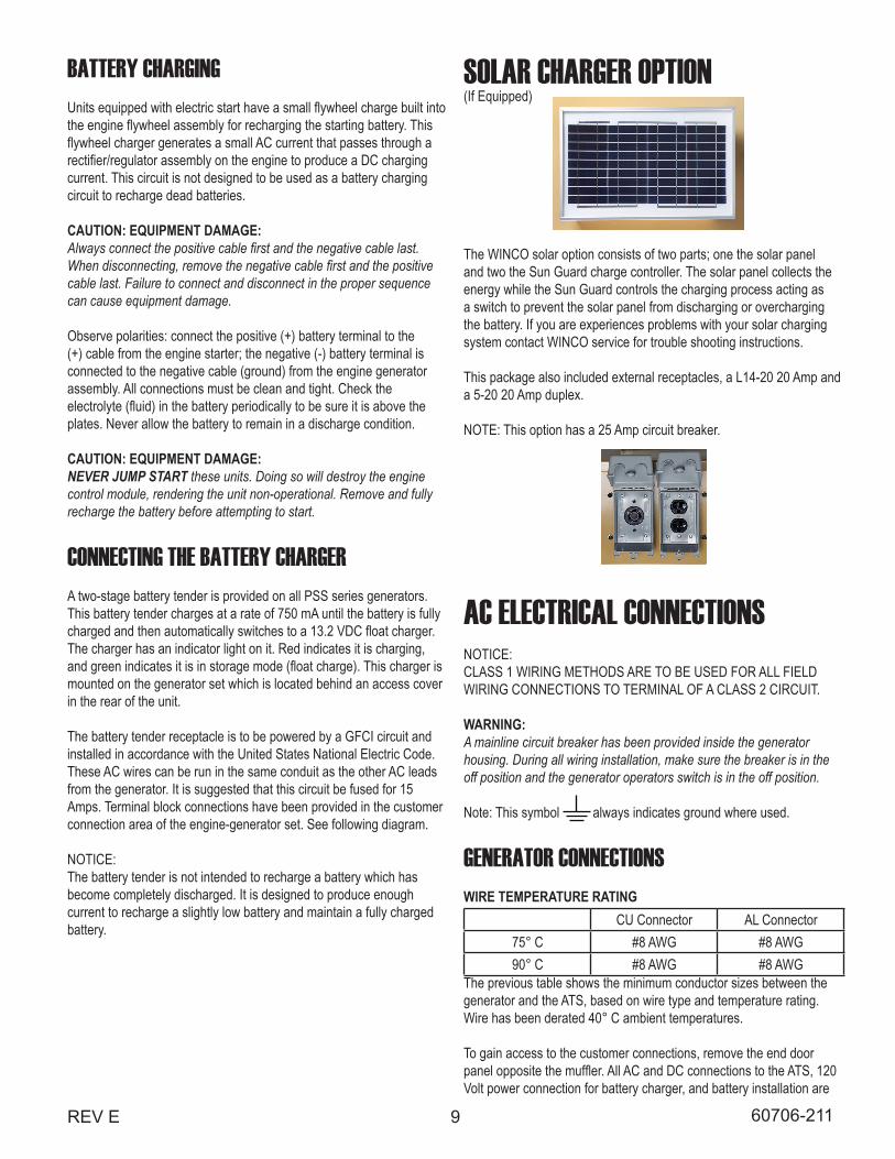
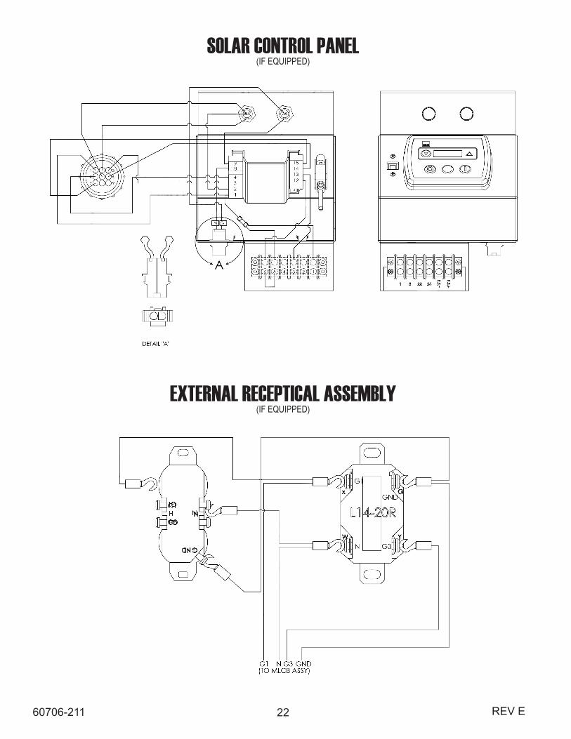
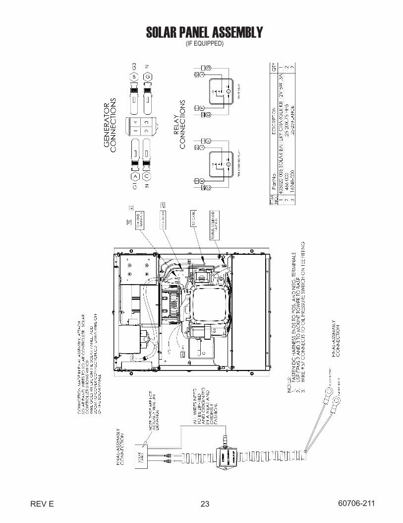
SOLAR CHARGER OPTION(If Equipped)
The WINCO solar option consists of two parts; one the solar panel and two the Sun Guard charge controller. The solar panel collects the energy while the Sun Guard controls the charging process acting as a switch to prevent the solar panel from discharging or overcharging the battery. If you are experiences problems with your solar charging system contact WINCO service for trouble shooting instructions.
This package also included external receptacles, a L14-20 20 Amp and a 5-20 20 Amp duplex.
NOTE: This option has a 25 Amp circuit breaker.
10 REV E60706-211
made behind this panel. See drawings for generator set and pad layout featured within this manual.
Two hot leads, one neutral, and one ground lead are required between the generator and the ATS or distribution panel. The two power leads from the generator are marked G1 and G3. Next install the two leads, one neutral, and one ground from the generator set to the ATS or distribution panel.
In addition to the power leads, install a three wire 120 Volt, 15 Amp circuit from your distribution panel to the generator. This circuit will be used to power the battery charger, optional block heater and optional battery heater.
The last four wires you will install are the DC control leads (14 or 16 gauge) for the start circuit in the ATS. These connections will be discussed later in more detail.
WINCO UL ATS (ASCO 185)See the ASCO installation manual for additional details on proper wiring of the Automatic Transfer Switch.
The standby generator terminals in the ATS are marked “ALTERNATE L2 & L6”. The “hot” leads G1 and G3 from the generator are connected to the terminals L2 & L6. The normal line power terminals in the ATS are marked “PREFERRED - L1 & L5”. The “hot” line power leads are L1 and L3 from the utility power supply. They are connected to terminals L1 and L5.
The load terminals in the ATS are marked “LOAD - L3 & L7”. The leads to the load distribution panel are connected to terminals L3 & L7.The neutral leads from all three locations are connected to the isolated terminal lugs on the sidewall of the cabinet. This terminal block is labeled “NEUTRAL” and the terminal lugs are mounted on red isolation standoffs.
The ground leads from all locations are connected to the grounded terminal lugs also located on the side wall. This set of terminals is labeled “GROUND”.
INSTALLATION NOTES:The load current carrying wires (L) and (T) must be sized to handle the maximum load current without excessive voltage drop. By code, the wire must be heavy enough to handle the full current rating of the main line circuit breaker (or fuse) in the entrance (or sub-panel) protecting the contactor switch. All wires should be installed in rigid or flexible conduit. Because of the many different types of service, feeder, and distribution equipment, no specific wiring instructions can be provided. It is, however, recommended that copper wire be used. In all cases it is essential that while the load is connected to the generator, there can be absolutely no feedback from the generator to the power line or the power line to the generator. When properly installed, the normal ATS control and safety systems will eliminate all paths for feedback. Check with your local electrical inspector on applicable local, state and federal codes.
WARNING:A service disconnect must be installed in front of the ATS panel as
DC ELECTRICAL INTERCONNECTIONCAUTION:Never run the AC and DC wiring on the same conduit.
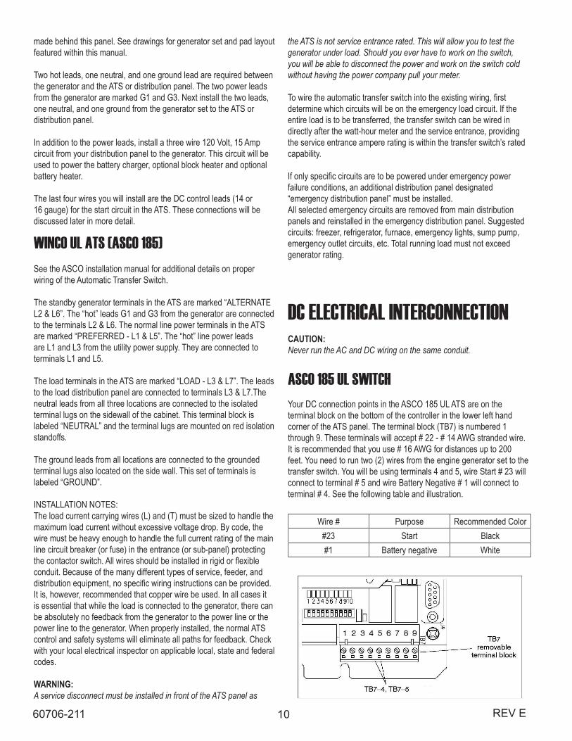
ASCO 185 UL SWITCHYour DC connection points in the ASCO 185 UL ATS are on the terminal block on the bottom of the controller in the lower left hand corner of the ATS panel. The terminal block (TB7) is numbered 1 through 9. These terminals will accept # 22 - # 14 AWG stranded wire. It is recommended that you use # 16 AWG for distances up to 200 feet. You need to run two (2) wires from the engine generator set to the transfer switch. You will be using terminals 4 and 5, wire Start # 23 will connect to terminal # 5 and wire Battery Negative # 1 will connect to terminal # 4. See the following table and illustration.
Wire # Purpose Recommended Color#23 Start Black#1 Battery negative White
the ATS is not service entrance rated. This will allow you to test the generator under load. Should you ever have to work on the switch, you will be able to disconnect the power and work on the switch cold without having the power company pull your meter.
To wire the automatic transfer switch into the existing wiring, first determine which circuits will be on the emergency load circuit. If the entire load is to be transferred, the transfer switch can be wired in directly after the watt-hour meter and the service entrance, providing the service entrance ampere rating is within the transfer switch’s rated capability.
If only specific circuits are to be powered under emergency power failure conditions, an additional distribution panel designated “emergency distribution panel” must be installed.All selected emergency circuits are removed from main distribution panels and reinstalled in the emergency distribution panel. Suggested circuits: freezer, refrigerator, furnace, emergency lights, sump pump, emergency outlet circuits, etc. Total running load must not exceed generator rating.
11REV E 60706-211
INITIAL START UPWARNING:DO NOT jump start these engine generator sets. Starting these units on a low battery of jump starting them will cause damage to the engine control module.
Use the following checklist to verify correct installation before starting the engine: □ Engine oil.* Check level & fill as required with proper grade/quantity. □ Unit mounting base properly bolted down. □ Clearance for service and maintenance on all sides. □ Proper fuel line material and size. □ All fuel line connections tight. □ Fuel line protected and a moisture trap installed (may be required for NG). □ LP/NG pressure OK. 4-6 oz. (7-11 in. WC). □ Battery connections clean and tight. □ Battery fully charged. □ All AC and DC wiring installed and properly protected.* Refer to engine owners manual for proper levels and types.After completing the above checklist, the engine generator set is ready for the initial start-up test.
START UP PROCEDUREENGINE-GENERATOR SET ONLY
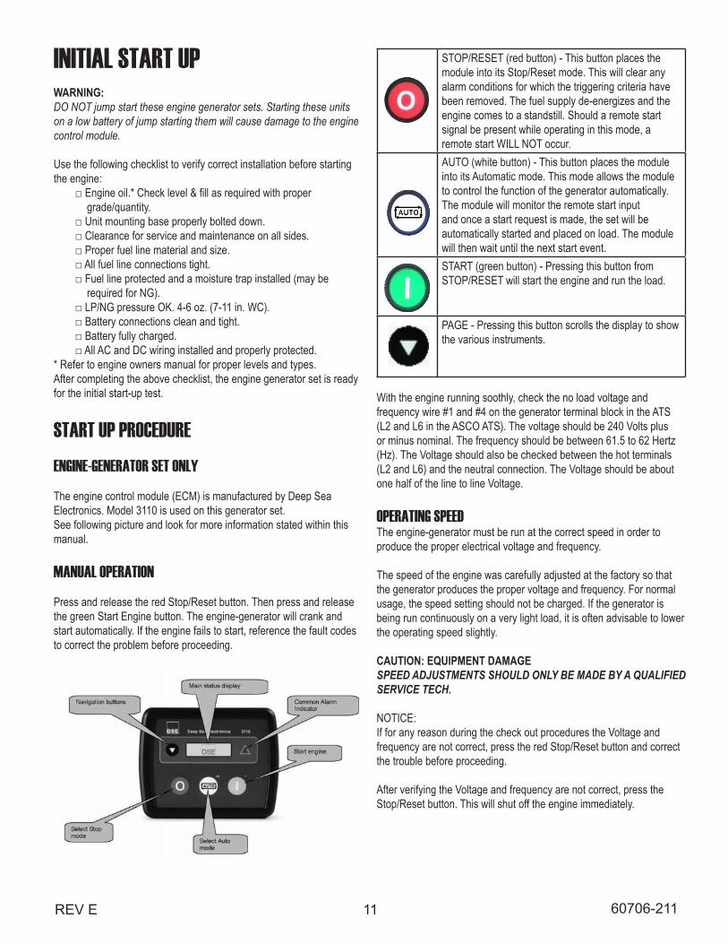
The engine control module (ECM) is manufactured by Deep Sea Electronics. Model 3110 is used on this generator set. See following picture and look for more information stated within this manual.
MANUAL OPERATION
Press and release the red Stop/Reset button. Then press and release the green Start Engine button. The engine-generator will crank and start automatically. If the engine fails to start, reference the fault codes to correct the problem before proceeding.
10 REV B60706-229
DC ELECTRICAL INTERCONNECTIONCAUTION:Never run the AC and DC wiring on the same conduit.
ASCO 185 UL SWITCHYour DC connection points in the ASCO 185 UL ATS are on the terminal block on the bottom of the controller in the lower left hand corner of the ATS panel. The terminal block (TB7) is numbered 1 through 9. These terminals will accept # 22 - # 14 AWG stranded wire. It is recommended that you use # 16 AWG for distances up to 200 feet. You need to run two (2) wires from the engine generator set to the transfer switch. You will be using terminals 4 and 5, wire Start # 23 will connect to terminal # 5 and wire Battery Negative # 1 will connect to terminal # 4. See the following table and illustration.
Wire # Purpose Recommended Color#23 Start Black#1 Battery negative White
INITIAL START UPWARNING:DO NOT jump start these engine generator sets. Starting these units on a low battery of jump starting them will cause damage to the engine control module.
Use the following checklist to verify correct installation before starting the engine:
grade/quantity.
required for NG).
* Refer to engine owners manual for proper levels and types.After completing the above checklist, the engine generator set is ready for the initial start-up test.
START UP PROCEDUREENGINE-GENERATOR SET ONLY
The engine control module (ECM) is manufactured by Deep Sea Electronics. Model 3110 is used on this generator set. See following picture and look for more information stated within this manual.
MANUAL OPERATION
Press and release the red Stop/Reset button. Then press and release the green Start Engine button. The engine-generator will crank and start automatically. If the engine fails to start, reference the fault codes to correct the problem before proceeding.
generator under load. Should you ever have to work on the switch, you will be able to disconnect the power and work on the switch cold without having the power company pull your meter.
determine which circuits will be on the emergency load circuit. If the entire load is to be transferred, the transfer switch can be wired in directly after the watt-hour meter and the service entrance, providing
capability.
failure conditions, an additional distribution panel designated “emergency distribution panel” must be installed.All selected emergency circuits are removed from main distribution panels and reinstalled in the emergency distribution panel. Suggested circuits: freezer, refrigerator, furnace, emergency lights, sump pump, emergency outlet circuits, etc. Total running load must not exceed generator rating.
STOP/RESET (red button) - This button places the module into its Stop/Reset mode. This will clear any alarm conditions for which the triggering criteria have been removed. The fuel supply de-energizes and the engine comes to a standstill. Should a remote start signal be present while operating in this mode, a remote start WILL NOT occur.AUTO (white button) - This button places the module into its Automatic mode. This mode allows the module to control the function of the generator automatically. The module will monitor the remote start input and once a start request is made, the set will be automatically started and placed on load. The module will then wait until the next start event.START (green button) - Pressing this button from STOP/RESET will start the engine and run the load.
PAGE - Pressing this button scrolls the display to show the various instruments.
With the engine running soothly, check the no load voltage and frequency wire #1 and #4 on the generator terminal block in the ATS (L2 and L6 in the ASCO ATS). The voltage should be 240 Volts plus or minus nominal. The frequency should be between 61.5 to 62 Hertz (Hz). The Voltage should also be checked between the hot terminals (L2 and L6) and the neutral connection. The Voltage should be about one half of the line to line Voltage.
OPERATING SPEEDThe engine-generator must be run at the correct speed in order to produce the proper electrical voltage and frequency.
The speed of the engine was carefully adjusted at the factory so that the generator produces the proper voltage and frequency. For normal usage, the speed setting should not be charged. If the generator is being run continuously on a very light load, it is often advisable to lower the operating speed slightly.
CAUTION: EQUIPMENT DAMAGESPEED ADJUSTMENTS SHOULD ONLY BE MADE BY A QUALIFIED SERVICE TECH.
NOTICE:If for any reason during the check out procedures the Voltage andfrequency are not correct, press the red Stop/Reset button and correctthe trouble before proceeding.
After verifying the Voltage and frequency are not correct, press the Stop/Reset button. This will shut off the engine immediately.
12 REV E60706-211
TRANSFER SWITCH & ENGINE-GENERATOR
Automatic (remote) OperationThis procedure checks the electrical operation of the automatic transfer switch. If the actual operation does not follow procedure, consult the trouble-shooting section in the transfer switch manual.
1. Turn on the preferred source (utility) circuit breaker. The Utility Acceptable Light should now come on, as well as the Load on Utility Light. If those lights fail to come on, recheck your incoming power to ensure you have 240 Volts nominal. If not, troubleshoot your utility source before continuing.
2. Press and release the Auto button on the engine control module (ECM). The auto mode icon will appear on the screen. The unit is now ready to be operated from the Automatic Transfer Switch.
3. Turn on the alternate source (generator) circuit breaker.
WARNING: PERSONAL INJURY HAZARD:Install front cover in transfer switch before operation. An electrical system fault could cause a flash and severe personal injury.
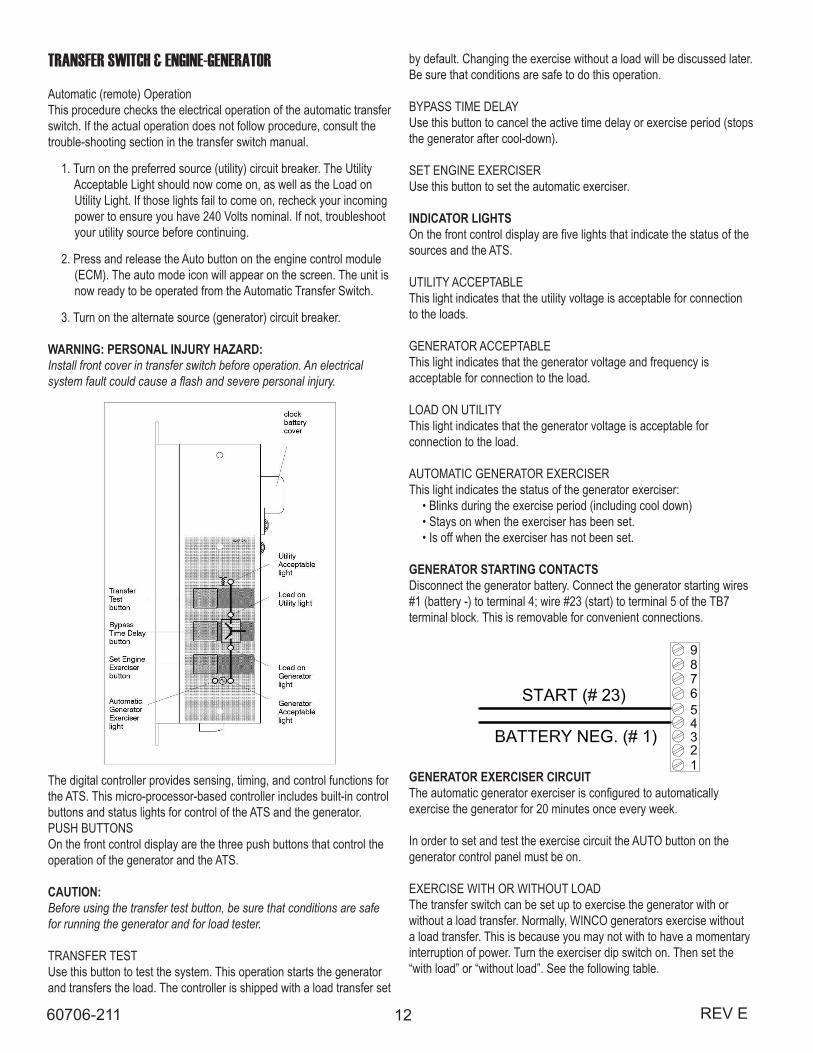
The digital controller provides sensing, timing, and control functions for the ATS. This micro-processor-based controller includes built-in control buttons and status lights for control of the ATS and the generator. PUSH BUTTONSOn the front control display are the three push buttons that control the operation of the generator and the ATS.
CAUTION:Before using the transfer test button, be sure that conditions are safe for running the generator and for load tester.
TRANSFER TESTUse this button to test the system. This operation starts the generator and transfers the load. The controller is shipped with a load transfer set
by default. Changing the exercise without a load will be discussed later. Be sure that conditions are safe to do this operation.
BYPASS TIME DELAYUse this button to cancel the active time delay or exercise period (stops the generator after cool-down).
SET ENGINE EXERCISERUse this button to set the automatic exerciser.
INDICATOR LIGHTSOn the front control display are five lights that indicate the status of the sources and the ATS.
UTILITY ACCEPTABLEThis light indicates that the utility voltage is acceptable for connection to the loads.
GENERATOR ACCEPTABLEThis light indicates that the generator voltage and frequency is acceptable for connection to the load.
LOAD ON UTILITYThis light indicates that the generator voltage is acceptable for connection to the load.
AUTOMATIC GENERATOR EXERCISERThis light indicates the status of the generator exerciser: • Blinks during the exercise period (including cool down) • Stays on when the exerciser has been set. • Is off when the exerciser has not been set.
GENERATOR STARTING CONTACTSDisconnect the generator battery. Connect the generator starting wires #1 (battery -) to terminal 4; wire #23 (start) to terminal 5 of the TB7 terminal block. This is removable for convenient connections.
GENERATOR EXERCISER CIRCUITThe automatic generator exerciser is configured to automatically exercise the generator for 20 minutes once every week.
In order to set and test the exercise circuit the AUTO button on the generator control panel must be on.
EXERCISE WITH OR WITHOUT LOADThe transfer switch can be set up to exercise the generator with or without a load transfer. Normally, WINCO generators exercise without a load transfer. This is because you may not with to have a momentary interruption of power. Turn the exerciser dip switch on. Then set the “with load” or “without load”. See the following table.
13REV E 60706-211
Function Factory Setting
Dip Switch
Dip Actuator
Actuator Position
Clock Battery Off S2 10 On (up)Off (down)
Exerciser Off S1 7 On (up)Off (down)
With load or without load
Without Load
S1 8 With (up) Without (down)
SETTING THE EXERCISERPress and hold (5 seconds) the Set Engine Exerciser button. The exercise period occurs immediately and at the same time weekly thereafter. The status light below the button blinks during the exercise period (including cool down). The light stays on to indicate that the exerciser has been set. If the light is off, the exerciser has not been set.
CANCELING AN ACTIVE EXERCISE PERIOD Press the Bypass Time Delay button to stop an exercising generator. If exercise with load is set, the ATS retransfers the load to the utility, then stops the generator after cooldown.
WARNING:With a total power failure (utility power fails and the generator fails to start and run), the exerciser must be reset after the power is restored.
The ASCO 185 has settings that can be changed for various applications. The dipswitch options are explained in the ASCO 185 Operator’s Manual.
This completes your installation and unit testing. ALWAYS leave the system in automatic mode unless servicing the unit. For automatic operation, the auto mode icon must be displayed on the engine controlmodule display.
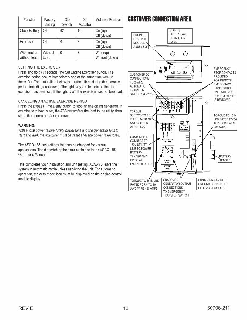
CUSTOMER CONNECTION AREA
CUSTOMER DC CONNECTIONS TO 2-WIRE AUTOMATIC TRANSFER SWITCH 1 & 22/23
ENGINE CONTROL MODULE ASSEMBLY
START & FUEL RELAYS LOCATED IN BACK
CUSTOMER TO CONNECT TO 120V UTILITY LINE TO POWER BATTERY TENDER AND OPTIONAL ENGINE HEATER
CUSTOMER GENERATOR OUTPUT CONNECTIONS TO EMERGENCY TRANSFER SWITCH
EMERGENCY STOP CONTACTS PROVIDED FOR REMOTE EMERGENCY STOP SWITCH UNIT WILL NOT RUN IF JUMPER IS REMOVED
BATTERY TENDER
CUSTOMER EARTH GROUND CONNECTED HERE AS REQUIRED
TORQUE TO 16 IN LBS RATED FOR 4 TO 10 AWG WIRE - 85 AMPS
TORQUE TO 16 IN LBS RATED FOR 4 TO 10 AWG WIRE - 85 AMPS
TORQUE SCREWS TO 9.6 IN LBS. 14 TO 16 AWG COPPER WITH LUGS
14 REV E60706-211
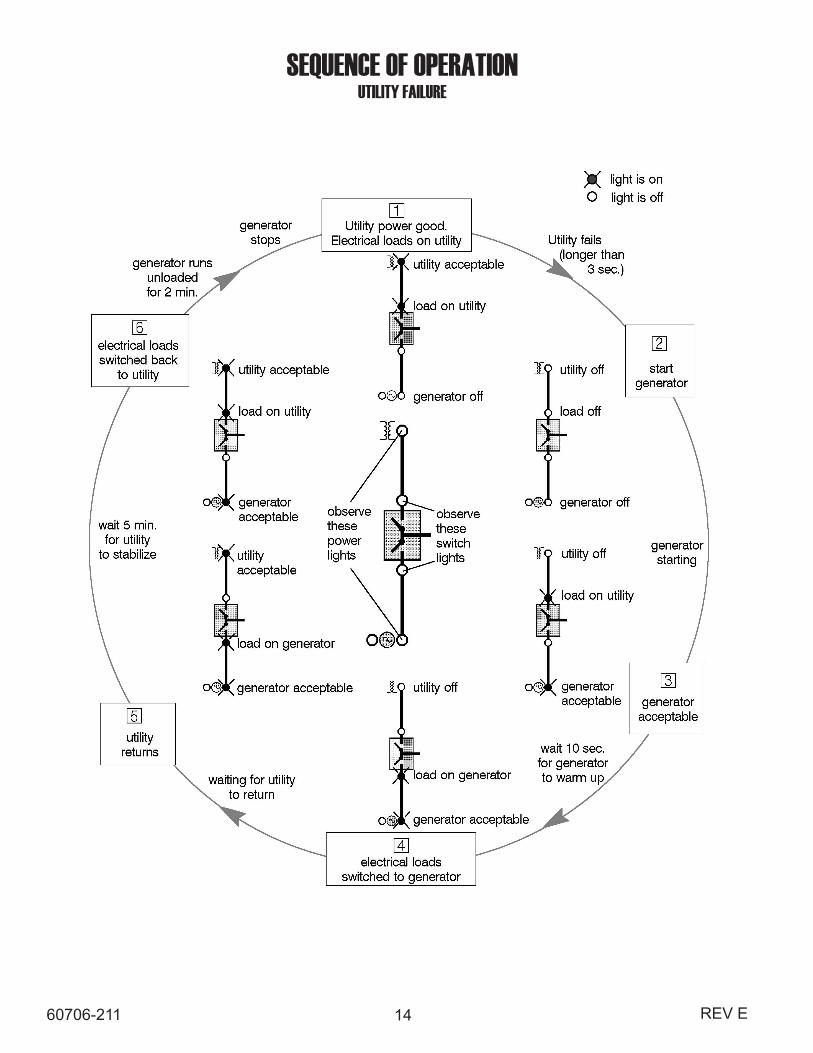
SEQUENCE OF OPERATIONUTILITY FAILURE
15REV E 60706-211
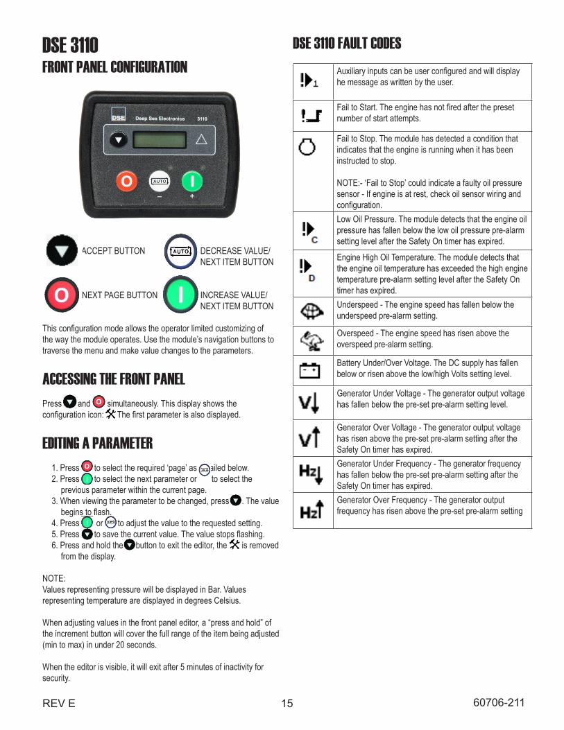
DSE 3110FRONT PANEL CONFIGURATION
ACCEPT BUTTON DECREASE VALUE/ NEXT ITEM BUTTON
NEXT PAGE BUTTON INCREASE VALUE/ NEXT ITEM BUTTON
This configuration mode allows the operator limited customizing of the way the module operates. Use the module’s navigation buttons to traverse the menu and make value changes to the parameters.
ACCESSING THE FRONT PANELPress and simultaneously. This display shows the configuration icon: The first parameter is also displayed.
EDITING A PARAMETER 1. Press to select the required ‘page’ as detailed below. 2. Press to select the next parameter or to select the previous parameter within the current page. 3. When viewing the parameter to be changed, press . The value begins to flash. 4. Press or to adjust the value to the requested setting. 5. Press to save the current value. The value stops flashing. 6. Press and hold the button to exit the editor, the is removed from the display.
NOTE: Values representing pressure will be displayed in Bar. Values representing temperature are displayed in degrees Celsius.
When adjusting values in the front panel editor, a “press and hold” of the increment button will cover the full range of the item being adjusted (min to max) in under 20 seconds.
When the editor is visible, it will exit after 5 minutes of inactivity for security.
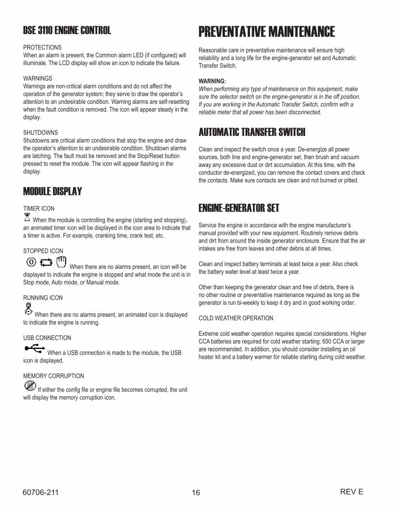
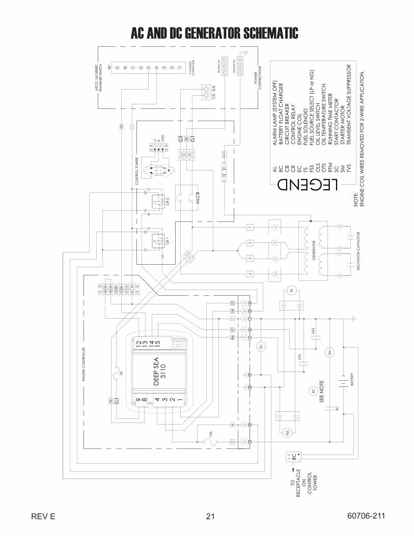
DSE 3110 FAULT CODESAuxiliary inputs can be user configured and will display he message as written by the user.
Fail to Start. The engine has not fired after the preset number of start attempts.
Fail to Stop. The module has detected a condition that indicates that the engine is running when it has been instructed to stop.
NOTE:- ‘Fail to Stop’ could indicate a faulty oil pressure sensor - If engine is at rest, check oil sensor wiring and configuration.Low Oil Pressure. The module detects that the engine oil pressure has fallen below the low oil pressure pre-alarm setting level after the Safety On timer has expired.
Engine High Oil Temperature. The module detects that the engine oil temperature has exceeded the high engine temperature pre-alarm setting level after the Safety On timer has expired.Underspeed - The engine speed has fallen below the underspeed pre-alarm setting.
Overspeed - The engine speed has risen above the overspeed pre-alarm setting.
Battery Under/Over Voltage. The DC supply has fallen below or risen above the low/high Volts setting level.
Generator Under Voltage - The generator output voltage has fallen below the pre-set pre-alarm setting level.
Generator Over Voltage - The generator output voltage has risen above the pre-set pre-alarm setting after the Safety On timer has expired.Generator Under Frequency - The generator frequency has fallen below the pre-set pre-alarm setting after the Safety On timer has expired.Generator Over Frequency - The generator output frequency has risen above the pre-set pre-alarm setting
16 REV E60706-211
DSE 3110 ENGINE CONTROLPROTECTIONSWhen an alarm is present, the Common alarm LED (if configured) will illuminate. The LCD display will show an icon to indicate the failure.
WARNINGSWarnings are non-critical alarm conditions and do not affect the operation of the generator system; they serve to draw the operator’s attention to an undesirable condition. Warning alarms are self-resetting when the fault condition is removed. The icon will appear steady in the display.
SHUTDOWNSShutdowns are critical alarm conditions that stop the engine and draw the operator’s attention to an undesirable condition. Shutdown alarms are latching. The fault must be removed and the Stop/Reset button pressed to reset the module. The icon will appear flashing in the display.
MODULE DISPLAYTIMER ICON
When the module is controlling the engine (starting and stopping), an animated timer icon will be displayed in the icon area to indicate that a timer is active. For example, cranking time, crank test, etc.
STOPPED ICON
When there are no alarms present, an icon will be displayed to indicate the engine is stopped and what mode the unit is in Stop mode, Auto mode, or Manual mode.
RUNNING ICON
When there are no alarms present, an animated icon is displayed to indicate the engine is running.
USB CONNECTION
When a USB connection is made to the module, the USB icon is displayed.
MEMORY CORRUPTION
If either the config file or engine file becomes corrupted, the unit will display the memory corruption icon.
PREVENTATIVE MAINTENANCEReasonable care in preventative maintenance will ensure high reliability and a long life for the engine-generator set and Automatic Transfer Switch.
WARNING:When performing any type of maintenance on this equipment, make sure the selector switch on the engine-generator is in the off position. If you are working in the Automatic Transfer Switch, confirm with a reliable meter that all power has been disconnected.
AUTOMATIC TRANSFER SWITCHClean and inspect the switch once a year. De-energize all power sources, both line and engine-generator set, then brush and vacuum away any excessive dust or dirt accumulation. At this time, with the conductor de-energized, you can remove the contact covers and check the contacts. Make sure contacts are clean and not burned or pitted.
ENGINE-GENERATOR SETService the engine in accordance with the engine manufacturer’s manual provided with your new equipment. Routinely remove debris and dirt from around the inside generator enclosure. Ensure that the air intakes are free from leaves and other debris at all times.
Clean and inspect battery terminals at least twice a year. Also check the battery water level at least twice a year.
Other than keeping the generator clean and free of debris, there is no other routine or preventative maintenance required as long as the generator is run bi-weekly to keep it dry and in good working order.
COLD WEATHER OPERATION
Extreme cold weather operation requires special considerations. Higher CCA batteries are required for cold weather starting; 650 CCA or larger are recommended. In addition, you should consider installing an oil heater kit and a battery warmer for reliable starting during cold weather.
17REV E 60706-211
ENGINE MAINTENANCECHECKING THE OIL LEVELThe oil level must always be checked before the engine is started.Refer to page 7 of this manual for instructions on checking the oil level.Take care to remove any dirt or debris from around the oil plug beforeremoving. Be sure the oil level is maintained.
CHANGING THE OILRefer to the Maintenance Schedule chart for required oil change intervals.
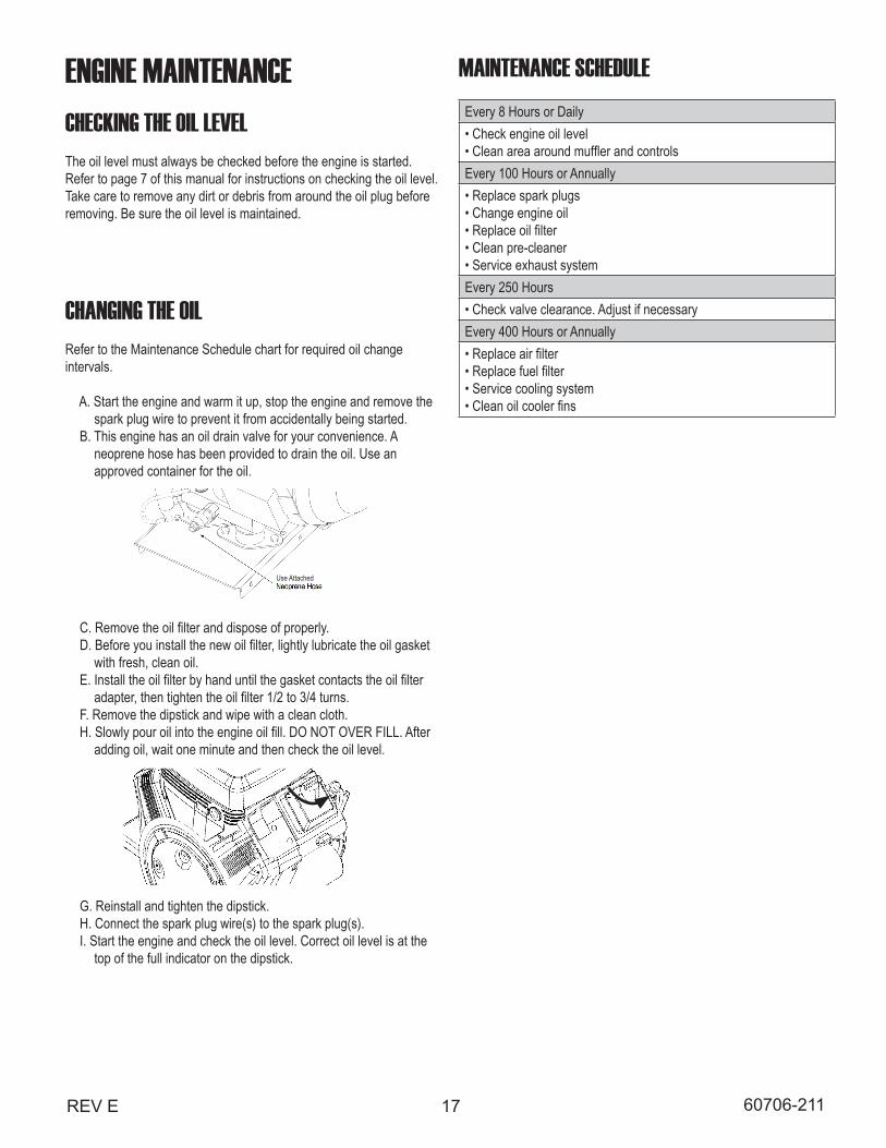
A. Start the engine and warm it up, stop the engine and remove the spark plug wire to prevent it from accidentally being started. B. This engine has an oil drain valve for your convenience. A neoprene hose has been provided to drain the oil. Use an approved container for the oil.
C. Remove the oil filter and dispose of properly. D. Before you install the new oil filter, lightly lubricate the oil gasket with fresh, clean oil. E. Install the oil filter by hand until the gasket contacts the oil filter adapter, then tighten the oil filter 1/2 to 3/4 turns. F. Remove the dipstick and wipe with a clean cloth. H. Slowly pour oil into the engine oil fill. DO NOT OVER FILL. After adding oil, wait one minute and then check the oil level.
G. Reinstall and tighten the dipstick. H. Connect the spark plug wire(s) to the spark plug(s). I. Start the engine and check the oil level. Correct oil level is at the top of the full indicator on the dipstick.
Use Attached
MAINTENANCE SCHEDULEEvery 8 Hours or Daily• Check engine oil level• Clean area around muffler and controlsEvery 100 Hours or Annually• Replace spark plugs• Change engine oil• Replace oil filter• Clean pre-cleaner• Service exhaust systemEvery 250 Hours• Check valve clearance. Adjust if necessaryEvery 400 Hours or Annually• Replace air filter• Replace fuel filter• Service cooling system• Clean oil cooler fins
18 REV E60706-211
TROUBLE SHOOTING TABLESWARNING:Never jump start these units. Jump starting these units with low or bad batteries will cause permanent damage to the engine control module.
UNIT WILL NOT CRANK WHEN THE POWER FAILS 1. Engine module not in the “Auto” mode. 2. Transfer switch control board not closing the contacts, 3. Low or dead battery, must hold 12 Volts during cranking. 4. Incorrect wiring between transfer switch and generator. 5. Loose or dirty battery terminals. 6. Defective engine control module (ECM). 7. Defective starter. 8. Defective start solenoid. 9. Defective start/stop control in the transfer switch. 10. ATS panel in fault from previous run cycle. 11. Blown 2 Amp fuse on generator control panel. 12. Blown 10 Amp fuse on generator control panel. 13. Defective starter/fuel solenoid relay(s).
ENGINE WILL NOT CRANK USING START BUTTON ON THE GENERATOR 1.Low or dead battery, must hold 12 Volts during cranking. 2. Blown 2 Amp fuse on generator control panel. 3. Blown 10 Amp fuse on generator control panel. 4. Loose or dirty battery terminals. 5. Defective engine control module (ECM). 6. Defective starter. 7. Defective start solenoid. 8. Locked up engine generator set. 9. Defective starter/fuel solenoid relays.
ENGINE CRANKS BUT WILL NOT START 1. Improper fuel pressure being delivered to unit. 2. Fuel supply shut-off. 3. Fuel supply empty. 4. Defective spark plug. 5. Defective engine ignition module. 6. Dirty air cleaner filter 7. Defective fuel solenoid valve. 8. Low Voltage from battery to fuel solenoid, must hold 12 Volts during cranking. 9. Oil in the bottom of the air cleaner from crankcase breather. 10. Defective starter/fuel solenoid relay(s).
ENGINE START AND THEN STOPS - Fault icon comes on 1. Engine is low on oil 2. No AC output from generator to engine stop crank circuit.
ENGINE WILL NOT COME UP TO SPEED AFTER IT STARTS 1. Insufficient fuel volume getting to the unit. a. Fuel line too small. b. Low fuel pressure. 2. AC short circuit. 3. Wiring to the ATS panel crossed and shorted. 4. Unit is overloaded. Check load amperage.
ATS PANEL WILL NOT TRANSFER TO EMERGENCY SUPPLY 1. No AC generator out put from generator. 2. See Automatic Transfer Switch Manual.
ATS PANEL WILL NOT PULL IN ON NORMAL POWER 1. See Automatic Transfer Switch Manual.
NO AC OUTPUT FROM GENERATOR 1. Defective diodes. 2, Defective voltage regulator. 3. Defective rotor. 4. Defective stator. 5. Defective exciter rotor. 6. Defective exciter stator. 7. AC short in the input leads. 8. Defective/Open breaker. 9. Wiring error.
19REV E 60706-211
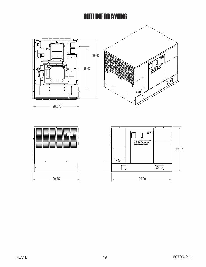
36.50
28.00
29.75 36.00
27.375
28.375
OUTLINE DRAWING
20 REV E60706-211
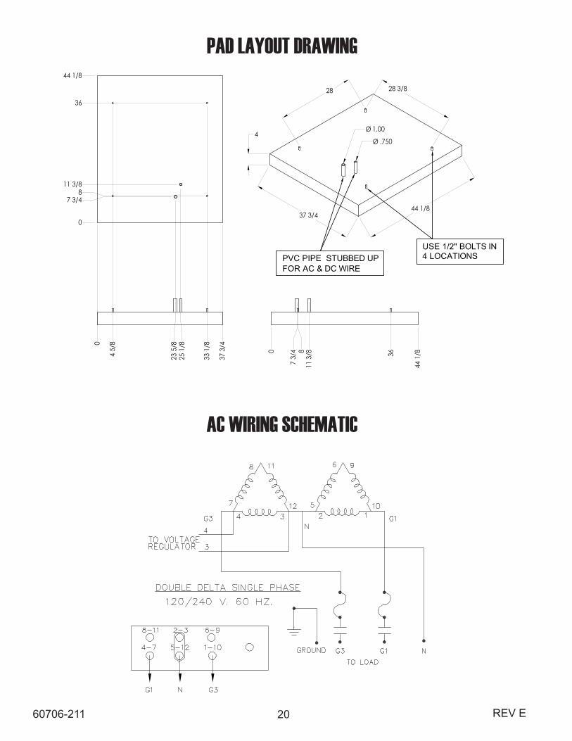
PAD LAYOUT DRAWING
11075-0020
60706-211
ENGINE GENERATOR SETPAD LAYOUT
AC WIRING SCHEMATIC
21REV E 60706-2112311075-01 60706-209
AC
AN
D D
C G
ENER
ATO
R S
CH
EMAT
IC
AL
ALA
RM L
AM
P (S
YSTE
M O
FF)
CB
CIR
CUI
T BR
EAKE
RC
R
C
ON
TRO
L RE
LAY
EC
ENG
INE
CO
ILFS
F
UEL
SOLE
NO
ID
OLS
OIL
LEV
EL S
WITC
H
RTM
RUN
NIN
G T
IME
MET
ERSC
ST
ART
CO
NTA
CTO
RSM
ST
ART
ER M
OTO
RTV
S
T
RAN
SIEN
T V
OLT
AG
E SU
PPRE
SSO
R
BC
BATT
ERY
FLO
AT
CHA
RGER
FSS
FUE
L SO
URC
E SE
LEC
T (L
P or
NG
)
LEGEND
POW
ERC
ON
NEC
TION
S
ASC
O 1
65 S
ERIE
STR
AN
SFER
SW
ITCH
9 8 7 6 5 4 3 2 1TB7
(L6)
NEU
TRA
L T/
B
43
21
(L2)
GRO
UND
T/B
9 PO
SITIO
NC
ON
NEC
TOR
G1NG3
GN
DNL1
GN
D
1524 23ES+
ES-
24
124
22
123
CO
NTR
OL
TOW
ER
ENG
INE
CO
NTR
OLL
ER
24
1
214
221
964
MLC
B
CR
1C
R 2
SC
13
49
85
2
EXC
ITATIO
N C
APA
CITO
R
GEN
ERA
TOR
BATT
ERY
FSS
FS
SM
SC
OLS
EC
+-BC
TORE
CEP
TAC
LEO
NC
ON
TRO
LTO
WER
123489
1514
10A
G1N
DEE
P SE
A31
10
2A
1312
OTS
OTS
OIL
TEM
PERA
TURE
SW
ITCH
37
76
NO
TE:
ENG
INE
CO
IL W
IRES
REM
OV
ED F
OR
2-W
IRE
APP
LIC
ATIO
N.
SEE
NO
TE
84
AC AND DC GENERATOR SCHEMATIC
22 REV E60706-211
EXTERNAL RECEPTICAL ASSEMBLY(IF EQUIPPED)
SOLAR CONTROL PANEL(IF EQUIPPED)
23REV E 60706-211
SOLAR PANEL ASSEMBLY(IF EQUIPPED)

24 REV E60706-211
12 MONTH LIMITED WARRANTYWINCO, Incorporated warrants to the original purchaser for 12 months or 1000 hours which ever occurs first, that goods manufactured or supplied by it will be free from defects in workmanship and material, provided such goods are installed, operated and maintained in accordance with WINCO written instructions.
WINCO’s sole liability, and Purchaser’s sole remedy for a failure under this warranty, shall be limited to the repair of the product. At WINCO’s option, material found to be defective in material or workmanship under normal use and service will be repaired or replaced. For warranty service, return the product within 12 months or 1000 hours which ever occurs first from the date of purchase, transportation charges prepaid, to your nearest WINCO Authorized Service Center or to WINCO, Inc. at Le Center Minnesota.
THERE IS NO OTHER EXPRESS WARRANTY.
To the extent permitted by law, any and all warranties, including those of merchantability and fitness for a particular purpose, are limited to 12 months or 1000 hours which ever occurs first, from date of purchase. In no event is WINCO liable for incidental or consequential damages.
Note: Some states do not allow limitation on the duration of implied warranty and some states do not allow the exclusion or limitation of incidental or consequential damages, so the above limitations may not apply in every instance. This warranty gives you specific legal rights which may vary from state to state.
WINCO reserves the right to change or improve its products without incurring any obligations to make such changes or improvement on products purchased previously.
EXCLUSIONS:
WINCO does not warrant Engines. Engines are covered exclusively by the warranties of their respective manufacturers, see enclosed warranties.
WINCO does not warrant Component Parts that are warranted by their respective manufacturers.
WINCO does not warrant modifications or alterations which were not made by WINCO, Inc.
WINCO does not warrant products which have been subjected to misuse and/or negligence or have been involved in an accident.
This warranty does not include travel time, mileage, or labor for removal or re-installation of WINCO product from its application.
WINCO INC. • 225 S. CORDOVA AVE. • LE CENTER, MN 56057 • 507-357-6821