Installation and Operational Instructions for ROBA ...
15
Installation and Operational Instructions for ROBA ® -twinstop ® Type 8012._ _ _ _ _ Sizes 150 to 350 (B.8012.GB) 05/07/2010 TK/HW/SU Chr. Mayr GmbH + Co. KG Tel.: 08341 / 804-0 Eichenstraße 1 Fax: 08341 / 804-421 D-87665 Mauerstetten http://www.mayr.de Page 1 of 15 Germany eMail: [email protected] Please read these Operational Instructions carefully and follow them accordingly! Ignoring these Instructions can lead to lethal accidents, malfunctions, brake failure and damage to other parts. Contents: Page 1: - Contents - Declaration of Conformity - Safety and Guideline Signs - TÜV (German Technical Inspectorate) Certification Page 2: - Safety Regulations Page 3: - Safety Regulations Page 4: - Brake Illustrations Page 5: - Parts List Page 6: - Table 1: Technical Data - Table 2: Technical Data Page 7: - Table 3: Technical Data - Table 4: Switching Times - Torque-Time Diagram Page 8: - Design - Function - State of Delivery - Application - Installation Conditions Page 9: - Installation of Type 8012._0_ _3 - Installation of Type 8012._1_ _3 Page 10: - Hand Release - Braking Torque Adjustment - Noise Damping Page 11: - Release Monitoring Page 12: - Wear Monitoring Page 13: - Electrical Connection (Operation with Nominal Voltage) Page 14: - Electrical Connection (Operation with Overexcitation) Page 15: - Brake Inspection (Customer-side after Installation) - Dual Circuit Brake Functional Inspection - Maintenance - Disposal - Malfunctions / Breakdowns Declaration of Conformity A conformity evaluation for the applicable EU directives has been carried out for this product. The conformity evaluation is set out in writing in a separate document and can be requested if required. It is forbidden to start use of the product until you have ensured that all applicable EU directives and directives for the machine or system into which the product has been installed have been fulfilled. Without a conformity evaluation, this product is not suitable for use in areas where there is a high danger of explosion. This statement is based on the ATEX directive. Safety and Guideline Signs Danger! Danger of injury to personnel and damage to machines. Please Observe! Guidelines on important points. TÜV (German Technical Inspectorate) Certification License number: ABV 845 Please Observe! According to German notation, decimal points in this document are represented with a comma (e.g. 0,5 instead of 0.5).
Transcript of Installation and Operational Instructions for ROBA ...
Installation and Operational Instructions for ROBA ®-twinstop ® Type 8012._ _ _ _ _ Sizes 150 to 350 (B.8012.GB)
05/07/2010 TK/HW/SU Chr. Mayr GmbH + Co. KG Tel.: 08341 / 804-0 Eichenstraße 1 Fax: 08341 / 804-421 D-87665 Mauerstetten http://www.mayr.de Page 1 of 15 Germany eMail: [email protected]
Please read these Operational Instructions carefull y and follow them accordingly! Ignoring these Instructions can lead to lethal acci dents, malfunctions, brake failure and damage to ot her parts.
Contents: Page 1: - Contents
- Declaration of Conformity
- Safety and Guideline Signs
- TÜV (German Technical Inspectorate) Certification
Page 2: - Safety Regulations
Page 3: - Safety Regulations
Page 4: - Brake Illustrations
Page 5: - Parts List
Page 6: - Table 1: Technical Data
- Table 2: Technical Data
Page 7: - Table 3: Technical Data
- Table 4: Switching Times
- Torque-Time Diagram
Page 8: - Design
- Function
- State of Delivery
- Application
- Installation Conditions
Page 9: - Installation of Type 8012._0_ _3
- Installation of Type 8012._1_ _3
Page 10: - Hand Release
- Braking Torque Adjustment
- Noise Damping
Page 11: - Release Monitoring
Page 12: - Wear Monitoring
Page 13: - Electrical Connection (Operation with Nominal Voltage)
Page 14: - Electrical Connection (Operation with Overexcitation)
Page 15: - Brake Inspection (Customer-side after Installation)
- Dual Circuit Brake Functional Inspection
- Maintenance
- Disposal
- Malfunctions / Breakdowns
Declaration of Conformity
A conformity evaluation for the applicable EU directives has been carried out for this product. The conformity evaluation is set out in writing in a separate document and can be requested if required. It is forbidden to start use of the product until you have ensured that all applicable EU directives and directives for the machine or system into which the product has been installed have been fulfilled. Without a conformity evaluation, this product is not suitable for use in areas where there is a high danger of explosion. This statement is based on the ATEX directive.
Safety and Guideline Signs
Danger! Danger of injury to personnel and damage to machines.
Please Observe! Guidelines on important points.
TÜV (German Technical Inspectorate) Certification
License number: ABV 845
Please Observe! According to German notation, decimal points in this document are represented with a comma (e.g. 0,5 instead of 0.5).
Installation and Operational Instructions for ROBA ®-twinstop ® Type 8012._ _ _ _ _ Sizes 150 to 350 (B.8012.GB)
05/07/2010 TK/HW/SU Chr. Mayr GmbH + Co. KG Tel.: 08341 / 804-0 Eichenstraße 1 Fax: 08341 / 804-421 D-87665 Mauerstetten http://www.mayr.de Page 2 of 15 Germany eMail: [email protected]
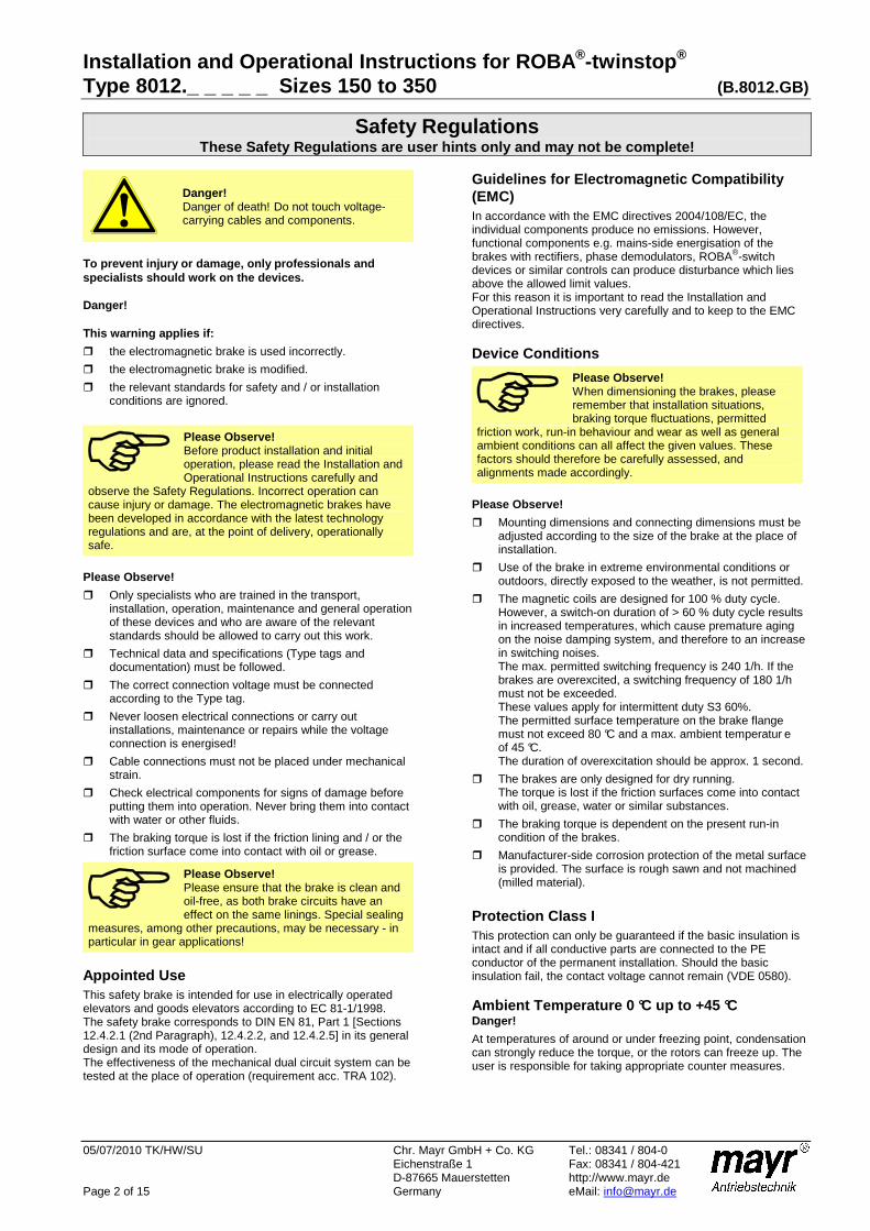
Safety Regulations These Safety Regulations are user hints only and ma y not be complete!
Danger! Danger of death! Do not touch voltage-carrying cables and components.
To prevent injury or damage, only professionals and specialists should work on the devices. Danger! This warning applies if:
the electromagnetic brake is used incorrectly.
the electromagnetic brake is modified.
the relevant standards for safety and / or installation conditions are ignored.
Please Observe! Before product installation and initial operation, please read the Installation and Operational Instructions carefully and
observe the Safety Regulations. Incorrect operation can cause injury or damage. The electromagnetic brakes have been developed in accordance with the latest technology regulations and are, at the point of delivery, operationally safe.
Please Observe!
Only specialists who are trained in the transport, installation, operation, maintenance and general operation of these devices and who are aware of the relevant standards should be allowed to carry out this work.
Technical data and specifications (Type tags and documentation) must be followed.
The correct connection voltage must be connected according to the Type tag.
Never loosen electrical connections or carry out installations, maintenance or repairs while the voltage connection is energised!
Cable connections must not be placed under mechanical strain.
Check electrical components for signs of damage before putting them into operation. Never bring them into contact with water or other fluids.
The braking torque is lost if the friction lining and / or the friction surface come into contact with oil or grease.
Please Observe! Please ensure that the brake is clean and oil-free, as both brake circuits have an effect on the same linings. Special sealing
measures, among other precautions, may be necessary - in particular in gear applications!
Appointed Use This safety brake is intended for use in electrically operated elevators and goods elevators according to EC 81-1/1998. The safety brake corresponds to DIN EN 81, Part 1 [Sections 12.4.2.1 (2nd Paragraph), 12.4.2.2, and 12.4.2.5] in its general design and its mode of operation. The effectiveness of the mechanical dual circuit system can be tested at the place of operation (requirement acc. TRA 102).
Guidelines for Electromagnetic Compatibility (EMC) In accordance with the EMC directives 2004/108/EC, the individual components produce no emissions. However, functional components e.g. mains-side energisation of the brakes with rectifiers, phase demodulators, ROBA®-switch devices or similar controls can produce disturbance which lies above the allowed limit values. For this reason it is important to read the Installation and Operational Instructions very carefully and to keep to the EMC directives. Device Conditions
Please Observe! When dimensioning the brakes, please remember that installation situations, braking torque fluctuations, permitted
friction work, run-in behaviour and wear as well as general ambient conditions can all affect the given values. These factors should therefore be carefully assessed, and alignments made accordingly.
Please Observe!
Mounting dimensions and connecting dimensions must be adjusted according to the size of the brake at the place of installation.
Use of the brake in extreme environmental conditions or outdoors, directly exposed to the weather, is not permitted.
The magnetic coils are designed for 100 % duty cycle. However, a switch-on duration of > 60 % duty cycle results in increased temperatures, which cause premature aging on the noise damping system, and therefore to an increase in switching noises. The max. permitted switching frequency is 240 1/h. If the brakes are overexcited, a switching frequency of 180 1/h must not be exceeded. These values apply for intermittent duty S3 60%. The permitted surface temperature on the brake flange must not exceed 80 °C and a max. ambient temperatur e of 45 °C. The duration of overexcitation should be approx. 1 second.
The brakes are only designed for dry running. The torque is lost if the friction surfaces come into contact with oil, grease, water or similar substances.
The braking torque is dependent on the present run-in condition of the brakes.
Manufacturer-side corrosion protection of the metal surface is provided. The surface is rough sawn and not machined (milled material).
Protection Class I This protection can only be guaranteed if the basic insulation is intact and if all conductive parts are connected to the PE conductor of the permanent installation. Should the basic insulation fail, the contact voltage cannot remain (VDE 0580). Ambient Temperature 0 °C up to +45 °C Danger!
At temperatures of around or under freezing point, condensation can strongly reduce the torque, or the rotors can freeze up. The user is responsible for taking appropriate counter measures.

Installation and Operational Instructions for ROBA ®-twinstop ® Type 8012._ _ _ _ _ Sizes 150 to 350 (B.8012.GB)
05/07/2010 TK/HW/SU Chr. Mayr GmbH + Co. KG Tel.: 08341 / 804-0 Eichenstraße 1 Fax: 08341 / 804-421 D-87665 Mauerstetten http://www.mayr.de Page 3 of 15 Germany eMail: [email protected]
Safety Regulations These Safety Regulations are user hints only and ma y not be complete!
Insulation Material Class F (+155 °C) The magnetic coil and the casting compound are suitable for use up to a maximum operating temperature of +155 °C. Brake Storage Store the brakes in a horizontal position, in dry rooms and
dust and vibration-free.
Relative air humidity < 60 %.
Temperature without major fluctuations within a range from – 20 ° up to +60° C.
Do not store in direct sunlight or UV light.
Do not store aggressive, corrosive substances (solvents / acids / lyes / salts etc.) near to the brakes.
For longer storage of more than 2 years, special measures are required (please contact the manufacturers). Handling Before installation, the brake must be inspected and found to be in proper condition. The brake function must be inspected both once installation has taken place as well as after longer system downtimes, in order to prevent the drive starting up against possibly seized linings. User-implemented Protective Measures: Please cover moving parts to protect against injury through
seizure.
Place a cover on the magnetic part to protect against injury through high temperatures.
Protect against electric shocks by installing a conductive connection between the magnetic component and the PE conductor on the permanent installation (Protection Class I) and by carrying out a standardised inspection of the continuous PE conductor connection to all contactable metal parts.
Protect against highly inductive switch-off peaks by installing varistors, spark quenching units or similar devices according to VDE 0580/2000-07, Paragraph 4.6, to prevent damage to the coil insulations or switch contact consumption in extreme conditions (this protection is contained in mayr® rectifiers).
Take precautions against freeze-up of the friction surfaces in high humidity and at low temperatures.
Regulations, Standards and Directives Used: DIN VDE 0580 Electromagnetic devices and components, general directives
2006/95/EC Low voltage directive
2004/108/EC EMC directive
95/16/EC Elevator directive
EN 81-1 Safety regulations for construction and installation of elevators and small goods elevators
BGV C1 (previously VGB 70) Safety regulations for theatre stage technical systems
Please Observe the Following Standards: DIN EN ISO 12100-1 and 2 Machine Safety
DIN EN 61000-6-4 Noise emission
EN12016 Interference resistance (for elevators, escalators and moving walkways)
EN 60204 Electrical machine equipment
Liability The information, guidelines and technical data in these
documents were up to date at the time of printing.
Demands on previously delivered brakes are not valid.
Liability for damage and operational malfunctions will not be taken if
- the Installation and Operational Instructions are ignored or neglected.
- the brakes are used inappropriately.
- the brakes are modified.
- the brakes are worked on unprofessionally.
- the brakes are handled or operated incorrectly.
Guarantee The guarantee conditions correspond with the
Chr. Mayr GmbH + Co. KG delivery conditions.
Mistakes or deficiencies are to be reported to mayr ® at once!
Conformity Markings The product confirms to the CE according to the low voltage directive 2006/95/EC. Identification mayr ® components are clearly marked and described on the Type tag:
Manufacturer
mayr ® Name/Type
Article number
Serial number

Installation and Operational Instructions for ROBA ®-twinstop ® Type 8012._ _ _ _ _ Sizes 150 to 350 (B.8012.GB)
05/07/2010 TK/HW/SU Chr. Mayr GmbH + Co. KG Tel.: 08341 / 804-0 Eichenstraße 1 Fax: 08341 / 804-421 D-87665 Mauerstetten http://www.mayr.de Page 4 of 15 Germany eMail: [email protected]
Fig. 1 Fig. 2 Fig. 3 Fig. 4
5
2
4 (4x)
1
1.1
6
12
1.1
6.6
5/9 (4x)
14 (8x)
1
13 Brake 1
Brake 2
1
2
3
2
8
Customer-side splined shaft
Air gap "b"
Air gap "b"
+0,2-0,05
+0,2-0,05
Air gap "a" 0,45
Air gap "a" 0,45
1
3
2
11
2
10
Air gap "b"
Air gap "b"
+0,2-0,05
+0,2-0,05
Air gap "a" 0,45
Air gap "a" 0,45

Installation and Operational Instructions for ROBA ®-twinstop ® Type 8012._ _ _ _ _ Sizes 150 to 350 (B.8012.GB)
05/07/2010 TK/HW/SU Chr. Mayr GmbH + Co. KG Tel.: 08341 / 804-0 Eichenstraße 1 Fax: 08341 / 804-421 D-87665 Mauerstetten http://www.mayr.de Page 5 of 15 Germany eMail: [email protected]
Parts List (Only use mayr original parts)
Item Name
1 Coil carrier assembly (incl. magnetic coils)
1.1 Coil cable 2 x AWG18 blue / brown
2 Armature disk
3 Rotor
4 Distance bolts
5
Hexagon head screw acc. DIN EN ISO 4014:
For Sizes 150 and 200: M8 x 110 / 8.8
For Size 250: M8 x 120 / 10.9
For Size 350: M10 x 120 / 8.8
6 Release monitoring assembly
6.1 Microswitch incl. adapter plate (Fig. 9; page 11)
6.2 Cap screw (Fig. 9; page 11)
6.3 Hexagon nut (Fig. 9; page 11)
6.4 Hexagon head screw (Fig. 9; page 11)
6.5 Spring washer (Fig. 9; page 11)
6.6 Microswitch cable 3 x AWG20 black / blue / brown
7 Hand release assembly (page 10)
7.1 Hand release lever (page 10)
7.2 Steel ball (page 10)
7.3 Thrust spring (page 10)
7.4 Cap screw (page 10)
7.5 Hexagon nut (page 10)
7.6 Washer (page 10)
8
O-ring NBR 70 (not included in delivery):
For Sizes 150 and 200: D48 x 3
For Size 250: D52 x 3
For Size 350 (braking torque up to 410 Nm): D52 x 3
For Size 350 (braking torque > 410 Nm): D60 x 3
9 Washer
10 Hub
11 O-ring
12 Cable clamp
13 Type tag
14 Noise damping
15 Wear monitoring assembly (page 12)
15.1 Microswitch incl. adapter plate (Fig. 10; page 12)
15.2 Cap screw (Fig. 10; page 12)
15.3 Hexagon nut (Fig. 10; page 12)
15.4 Hexagon head screw (Fig. 10; page 12)
15.5 Spring washer (Fig. 10; page 12)
Installation and Operational Instructions for ROBA ®-twinstop ® Type 8012._ _ _ _ _ Sizes 150 to 350 (B.8012.GB)
05/07/2010 TK/HW/SU Chr. Mayr GmbH + Co. KG Tel.: 08341 / 804-0 Eichenstraße 1 Fax: 08341 / 804-421 D-87665 Mauerstetten http://www.mayr.de Page 6 of 15 Germany eMail: [email protected]
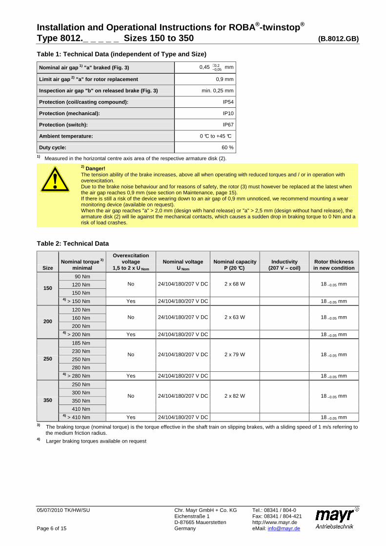
Table 1: Technical Data (independent of Type and Si ze)
Nominal air gap 1) "a" braked (Fig. 3) 0,45 2,005,0
+− mm
Limit air gap 2) "a" for rotor replacement 0,9 mm
Inspection air gap "b" on released brake (Fig. 3) min. 0,25 mm
Protection (coil/casting compound): IP54
Protection (mechanical): IP10
Protection (switch): IP67
Ambient temperature: 0 °C to +45 °C
Duty cycle: 60 %
1) Measured in the horizontal centre axis area of the respective armature disk (2).
2) Danger! The tension ability of the brake increases, above all when operating with reduced torques and / or in operation with overexcitation. Due to the brake noise behaviour and for reasons of safety, the rotor (3) must however be replaced at the latest when the air gap reaches 0,9 mm (see section on Maintenance, page 15). If there is still a risk of the device wearing down to an air gap of 0,9 mm unnoticed, we recommend mounting a wear monitoring device (available on request). When the air gap reaches "a" > 2,0 mm (design with hand release) or "a" > 2,5 mm (design without hand release), the armature disk (2) will lie against the mechanical contacts, which causes a sudden drop in braking torque to 0 Nm and a risk of load crashes.
Table 2: Technical Data
Size Nominal torque 3)
minimal
Overexcitation voltage
1,5 to 2 x U Nom Nominal voltage
U Nom Nominal capacity
P (20 °C) Inductivity
(207 V – coil) Rotor thickness in new condition
90 Nm
120 Nm
150 Nm
No 24/104/180/207 V DC 2 x 68 W 18 –0.05 mm 150
4) > 150 Nm Yes 24/104/180/207 V DC 18 –0.05 mm
120 Nm
160 Nm
200 Nm
No 24/104/180/207 V DC 2 x 63 W 18 –0.05 mm 200
4) > 200 Nm Yes 24/104/180/207 V DC 18 –0.05 mm
185 Nm
230 Nm
250 Nm
280 Nm
No 24/104/180/207 V DC 2 x 79 W 18 –0.05 mm 250
4) > 280 Nm Yes 24/104/180/207 V DC 18 –0.05 mm
250 Nm
300 Nm
350 Nm
410 Nm
No 24/104/180/207 V DC 2 x 82 W 18 –0.05 mm 350
4) > 410 Nm Yes 24/104/180/207 V DC 18 –0.05 mm 3) The braking torque (nominal torque) is the torque effective in the shaft train on slipping brakes, with a sliding speed of 1 m/s referring to the medium friction radius. 4) Larger braking torques available on request

Installation and Operational Instructions for ROBA ®-twinstop ® Type 8012._ _ _ _ _ Sizes 150 to 350 (B.8012.GB)
05/07/2010 TK/HW/SU Chr. Mayr GmbH + Co. KG Tel.: 08341 / 804-0 Eichenstraße 1 Fax: 08341 / 804-421 D-87665 Mauerstetten http://www.mayr.de Page 7 of 15 Germany eMail: [email protected]
Table 3: Technical Data
Size Max. permitted friction work
per single circuit 5)
Inspected max. speed in the elevator area as
prototype-inspected brake
Tightening torque on fixing screw
Item 5 Weight
150 17500 J 1000 rpm 24 Nm 19,6 kg
200 16500 J 1000 rpm 24 Nm 23,7 kg
250 25500 J 1000 rpm 36 Nm 27,0 kg
350 23500 J 1000 rpm 48 Nm 34,9 kg 5) Values apply for a speed of 400 rpm and nominal torque. The value can be doubled for both brake circuits. The value increases at lower speeds and decreases at higher speeds (please contact mayr ®). Table 4: Switching Times
Size Nominal torque
minimal Tightening t 2
Tightening t 2 on overexcitation
Drop-out t 11 AC
Drop-out t 1 AC
Drop-out t 11 DC
Drop-out t1 DC
90 Nm 145 250 570 35 140
120 Nm 170 200 510 27 125
150 Nm 200 150 450 20 110 150
> 150 Nm Approx. 120
120 Nm 170 420 980 75 230
160 Nm 225 310 790 53 195
200 Nm 280 190 620 30 160 200
> 200 Nm Approx. 170
185 Nm 210 300 720 50 180
230 Nm 260 240 640 40 165
250 Nm 285 215 590 37 155
280 Nm 310 180 540 25 140
250
> 280 Nm Approx. 190
250 Nm 290 370 700 45 150
300 Nm 330 320 640 40 140
350 Nm 370 270 580 37 130
410 Nm 400 200 510 30 110
350
> 410 Nm Approx. 240
Please Observe:
The use of varistors for spark quenching increases the DC-side switching times.
At temperatures of around or under freezing point, condensation can strongly reduce the braking torque. The user is responsible for taking appropriate counter measures. The customer is responsible for providing a protective cover against contamination caused by construction sites.
Torque-Time Diagram
Key:
M1 = Switching torque M2 = Nominal torque (characteristic torque) M4 = Transmittable torque M6 = Load torque t1 = Connection time t11 = Response delay on connection t2 = Separation time t21 = Response delay on separation t4 = Slipping time + t11
M
M2
M6
t11 t21
t2
t
t
P
t4
t1
M1
M4
0,1 M2
ON
OFF

Installation and Operational Instructions for ROBA ®-twinstop ® Type 8012._ _ _ _ _ Sizes 150 to 350 (B.8012.GB)
05/07/2010 TK/HW/SU Chr. Mayr GmbH + Co. KG Tel.: 08341 / 804-0 Eichenstraße 1 Fax: 08341 / 804-421 D-87665 Mauerstetten http://www.mayr.de Page 8 of 15 Germany eMail: [email protected]
Design
The ROBA®-twinstop® is a spring applied, electromagnetically releasing dual circuit brake. It is used for installation in a gearless elevator and serves as a brake assembly on the drive sheave shaft and as part of the protective assembly against excessive upward-moving cage speeds. Function
ROBA®-twinstop® brakes are spring applied, electromagnetic safety brakes.
Spring applied function: In de-energised condition, thrust springs press against the armature disks (2). The rotor (3) with the friction linings is therefore held between the armature disks (2) and the machine screw-on surface. The motor shaft is braked by the rotor (3).
Electromagnetic: Due to the magnetic force of the coils in the coil carriers (1), the armature disk (2) is attracted against the spring force to the coil carrier (1). The brake is released and the shaft can rotate freely.
Safety brake function: The ROBA®-twinstop® brakes reliably and safely in the event of a power switch-off, a power failure or an emergency STOP. State of Delivery
The brake body is partly assembled with armature disks (2), distance bolts (4), adjusted microswitches (option, dependent on Type) and hand release (Item 7 / option, dependent on Type). The rotor (3), hexagon head screws (5), washers (9) and the hub (10) with O-ring (11) are included loose in delivery. Please check state of delivery! Application
ROBA®-twinstop ® for use as holding brakes with occasional emergency STOP braking actions.
The max. permitted speeds and friction work, see Table 3, must be observed.
Fig. 5
Installation Conditions
The eccentricity of the shaft end in relation to the fixing holes must not exceed 0,3 mm.
The position tolerance of the threaded holes for the hexagon head screws (5) must not exceed 0,3 mm.
The axial run out deviation of the screw-on surface to the shaft must not exceed the permitted axial run out tolerance of 0,063 mm in the area of the friction surface. Measuring procedure acc. DIN 42955. Larger deviations can lead to a drop in torque, to continuous slipping on the rotor (3) and to overheating.
The toothed motor shaft (Type 8012._0_ _3) should be designed according to the information given in the applicable assembly drawing. The O-ring groove must be inserted before the shaft is splined. The O-ring groove must be free of burrs.
Please Observe! The dimensions on the assembly drawings are manufacturer-side recommendations.
On hub designs (Type 8012._1_ _3), the hub bore (10) tolerances and the shaft must be selected so that the hub toothing (10) is not widened. Widening of the toothing leads to the rotor (3) jamming on the hub (10) and therefore to brake malfunctions. Recommended hub - shaft tolerance H7/k6. If the hub (10) is heated for better joining, the O-ring (11) must be removed beforehand and re-mounted after hub installation. The max. permitted joining temperature of 200 °C mu st not be exceeded.
Dimensioning of the key connection according to the requirements shaft diameter, transmittable torque and operating conditions must be carried out. For this, the corresponding user data must be known or the customer must carry out the dimensioning according to the valid calculation basis DIN 6892. For the calculation, a hub quality of Re = 300 N/mm2 should be used. The length of the key should lie over the entire hub (10).
For the dimensioning of the key connections, the permitted tensions common in machine construction must be considered.
The mounting dimensions and the screw-on surface s with depth K + 2 mm (K = screw projection) acc. Catalogue or applicable assembly drawing must be given (Fig. 5).
The rotor and brake surfaces must be oil and grease-free. A suitable counter friction surface (steel or cast iron) must be used. Sharp-edged interruptions on the friction surfaces must be avoided. Recommended surface quality in the area of the friction surface Ra = 1,6 µm. In particular customer-side mounting surfaces made of grey cast iron are to be rubbed down additionally w ith fine sandpaper (grain ≈≈≈≈ 200 – 400), or ideally with a sander.
Please abstain from using cleaning agents containing solvents, as they could affect the friction material.
During longer downtimes, we recommend the use of suitable corrosion protection measures for the mounting surface (e.g. zinc-phosphate coating) until initial operation.
0,063 A
A
Ra
1,6
Ks s
Ø 0,3
Mountingsurface
Motor shaft centre axis

Installation and Operational Instructions for ROBA ®-twinstop ® Type 8012._ _ _ _ _ Sizes 150 to 350 (B.8012.GB)
05/07/2010 TK/HW/SU Chr. Mayr GmbH + Co. KG Tel.: 08341 / 804-0 Eichenstraße 1 Fax: 08341 / 804-421 D-87665 Mauerstetten http://www.mayr.de Page 9 of 15 Germany eMail: [email protected]
Installation of Type 8012._0_ _3 (Figs. 1 - 3) (Design with toothed motor shaft)
1. Insert the O-ring (8), slightly greased, acc. Parts List with NBR 70 material (provided by customer) into the motor shaft groove. Please use NLGI Class 2 grease with a basic oil viscosity of 220 mm2/s at 40 °C, e.g. Mobilgrease HP222.
2. Push the rotor (3) onto the motor shaft by hand using light pressure. Please observe that the longer rotor collar faces away from the machine wall on Sizes 150 und 200, the installation direction is unimportant on Size 250, because the rotor (3) is symmetrical, the graduated rotor collar faces away from the machine wall on Size 350. Check that the toothing moves easily. Do not damage the O-ring.
3. Secure the brake bodies using 4 hexagon head screws (5) and washers (9) all-round step-wise evenly (we recommend that you secure the screws using Loctite 243). Tighten the hexagon head screws using a torque wrench and observe the tightening torque acc. Table 3.
4. Check air gap "a" = 0,45 2,005,0
+− mm (Fig. 3).
The nominal air gap must be in the horizontal centre axis area on both armature disks (2) (Fig. 1).
5. Check air gap "b" > 0,25 mm in energised state on t he rotor (3) (Fig. 3). The inspection air gap must be given.
Installation of Type 8012._1_ _3 (Figs. 1, 2 and 4) (Hub Design)
1. Mount the hub (10) with the O-ring inserted (Item 11 / O-ring must be lightly greased ) onto the shaft and bring it into the correct position (the length of the key should cover the entire hub) and secure it axially e.g. using a locking ring).
2. Push the rotor (3) over the O-ring (11) onto the hub (10) by hand using light pressure. Please observe the the rotor collar (on Size 150, the longer rotor collar) is facing the machine wall. Ensure that the toothing moves easily. Do not damage the O-ring.
3. Secure the brake bodies using 4 hexagon head screws (5) and washers (9) all round step-wise evenly (we recommend that you secure the screws using Loctite 243). Tighten the hexagon head screws using a torque wrench and observe the tightening torque acc. Table 3.
4. Check air gap "a" = 0,45 2,005,0
+− mm (Fig. 4).
The nominal air gap must be given in the horizontal centre axis area on both armature disks (2) (Fig. 1).
5. Check air gap "b" > 0,25 mm in energised state on t he rotor (3) (Fig. 4). The inspection air gap must be given.

Installation and Operational Instructions for ROBA ®-twinstop ® Type 8012._ _ _ _ _ Sizes 150 to 350 (B.8012.GB)
05/07/2010 TK/HW/SU Chr. Mayr GmbH + Co. KG Tel.: 08341 / 804-0 Eichenstraße 1 Fax: 08341 / 804-421 D-87665 Mauerstetten http://www.mayr.de Page 10 of 15 Germany eMail: [email protected]
Hand Release (7) (Option dependent on Type for mechanical release of both brake circuits individually using a Bowden cable or by hand)
Danger! Operate the hand release carefully. Existing loads are put into motion when the hand release is activated.
The hand release is completely assembled manufactur er-side. The brake is released when both hand release levers are moved simultaneously (7.1), see Figs. 7 and 8. By lifting the hand release levers (7.1) up from the steel balls (7.2), both cap screws (7.4) incl. washers (7.6) together with the armature disk (2) are pulled against the coil carrier (1) (Fig. 6). The rotor (3) is then free, thus releasing the brake. Table 5: Technical Data
Release force per braking circuit with
Size Braking torque Bowden cable
Hand release lever
150 150 Nm Approx. 160 N Approx. 95 N
200 200 Nm Approx. 200 N Approx. 120 N
250 280 Nm Approx. 280 N Approx. 165 N
350 410 Nm Approx. 370 N Approx. 215 N
Fig. 6
Fig. 7 (Hand release for Bowden cable) Fig. 8 (Hand release with hand release lever) Braking Torque Adjustment
ROBA®-twinstop ® brakes are delivered adjusted to the braking torque required on order.
Noise Damping (Item 14 / Fig. 2)
The noise damping used here was set and adjusted manufacturer-side. However, this component is subje ct to aging dependent on the application or operational conditions (torque adjustment, switching frequency, ambient conditions, system vibrations etc.)
Please Observe! Replacing the damping element is only permitted at the mayr ® site of manufacture.
7.6
3
2
7.3 7.4 1 7.2
7.1
7.5Adjustment dimension
2,0 +0,3 mm

Installation and Operational Instructions for ROBA ®-twinstop ® Type 8012._ _ _ _ _ Sizes 150 to 350 (B.8012.GB)
05/07/2010 TK/HW/SU Chr. Mayr GmbH + Co. KG Tel.: 08341 / 804-0 Eichenstraße 1 Fax: 08341 / 804-421 D-87665 Mauerstetten http://www.mayr.de Page 11 of 15 Germany eMail: [email protected]
Release Monitoring (6) Fig. 9 (Option, dependent on Type)
ROBA®-twinstop ® brakes are delivered with one release monitoring (6) per brake circuit. The microswitches (6.1) emit a signal for every brake condition change "signal brake opened or brake closed“
On initial operation: Connection as NO contact (black and blue strands).
The customer is responsible for a signal evaluation of both conditions.
From the point at which the brake is energised, a time span of three times the separation time must pass before the microswitch signal on the release monitoring is evaluated.
Wiring Diagram:
Re-adjustment is possible via the hexagon head screws (6.4) and the hexagon nuts (6.3). If this proves necessary, please contact the manufacturers. Function
When the magnetic coils are energised in the coil carriers (1), the armature disks (2) are attracted to the coil carrier (1), the microswitches (6.1) emit a signal and the brake is released.
Fig. 9
Manufacturer-side Adjustment and Functional Inspection of the Microswitch (6.1), see Fig. 9
Danger! The brake is mounted, secured to the tightening torque (see Table 3) and the coil is de-energised.
1. Turn the hexagon head screw (6.4) in the direction of the microswitch (6.1) up to the microswitch tappet.
2. Tighten the hexagon nut (6.3), so that the hexagon head screw (6.4) is placed under pre-tension by the spring washer (6.5).
3. Put a feeler gauge 0,12 mm (loose sensor plate) between the switch tappet and the hexagon head screw (6.4).
4. Connect the inspection or measurement device (diode inspection) to the NO contact black/blue.
5. Turn the hexagon head screw (6.4) in the direction of the switch (6.1) up to signal "ON", turn it back to the signal "OFF" and counter the hexagon head screw (6.4) with the hexagon nut (6.3).
6. Energise brake Signal "ON" , De-energise brake Signal "OFF" , Re-adjust if necessary and repeat the inspection.
7. Inspection with feeler gauge 0,16 mm energised Signal "ON" de-energised Signal "ON"
8. Inspection with feeler gauge 0,12 mm energised Signal "ON" de-energised Signal "OFF"
9. Put the feeler gauge 0,20 mm between the armature disk (2) and the coil carrier (1) in the microswitch (6.1) area and then energise the brake. The signal must be "ON".
10. Paint items 6.2, 6.3 and 6.4 with sealing lacquer. Customer-side Inspection after Mounting onto the Elevator Machine
The customer-side contact is an NO contact. Please inspect the release monitoring of both circuits: Brake de-energised Signal "OFF", Brake energised Signal "ON"
Table 6: Microswitch Specifications (6.1)
Characteristic values for measurement:
250 V~ / 3 A
Minimum switching capacity: 12 V, 10 mA DC-12
Recommended switching capacity: for maximum lifetime and reliability
24 V, 10...50 mA DC-12 DC-13 with free-wheeling diode!
Usage category acc. IEC 60947-5-1: DC-12 (resistance load), DC-13 (inductive load)
6.3 6.1 6.26.5 6.4 12
14
2
NC ContactGrey onnection Connection whenbrake closed
c
NO Contactblue connection Connection whenbrake released
COM Contactlack cB onnection

Installation and Operational Instructions for ROBA ®-twinstop ® Type 8012._ _ _ _ _ Sizes 150 to 350 (B.8012.GB)
05/07/2010 TK/HW/SU Chr. Mayr GmbH + Co. KG Tel.: 08341 / 804-0 Eichenstraße 1 Fax: 08341 / 804-421 D-87665 Mauerstetten http://www.mayr.de Page 12 of 15 Germany eMail: [email protected]
Wear Monitoring (15) Fig. 10 (Option, dependent on Type)
Only one microswitch for wear monitoring (15) is required per ROBA®-twinstop ®, which is mounted onto the brake as shown in Fig. 10. The ROBA®-twinstop ® brake is delivered with manufacturer-side adjusted wear monitoring (15). Function
Due to wear on the rotor, (3) the air gap "a" between the coil carrier (1) and the armature disk increases (2). Once the maximum air gap (limit air gap) of 0,9 mm has been reached (Table 1), the microswitch contact (15.1) switches over and emits a signal. The rotor (3) must be replaced.
The customer is responsible for signal evaluation.
Wiring Diagram: Before replacing the rotor (3)
• Clean the brake and remove abraded particles using compressed air.
• Do not inhale brake dust.
• Measure the rotor thickness "new" (see Table 2).
Replacing the rotor (3) Replace the rotor by following the Brake Installati on instructions backwards.
Danger! The drive brake must be load-free on hoist drives. Otherwise there is a danger of load crashes!
Table 7: Microswitch Specifications (15.1)
Characteristic values for measurement:
250 V~ / 3 A
Minimum switching capacity: 12 V, 10 mA DC-12
Recommended switching capacity: for maximum lifetime and reliability
24 V, 10...50 mA DC-12 DC-13 with free-wheeling diode!
Usage category acc. IEC 60947-5-1: DC-12 (resistance load), DC-13 (inductive load)
Manufacturer-side Adjustment and Functional Inspection of the Microswitch (15.1), see Fig. 10
Danger! The brake is mounted, secured to the tightening torque (see Table 3) and the coil is de-energised.
1. Connect the inspection or measurement device (diode inspection) to the NC contact black/grey.
2. Turn the hexagon head screw (15.4) in the direction of the microswitch (15.1) until it switches, and apply pre-tension via the spring washer (15.5) using the hexagon nut (15.3).
3. Hold the hexagon nut (15.3) and turn the hexagon head screw (15.4) back until the microswitch contact (15.1) switches over again.
4. Mark the position of the hexagon head screw (15.4) (marker pen).
5. Hold the hexagon head screw (15.3) and turn the hexagon head screw (15.4) approx. 0,6 – 0,7 turns back in the direction of the microswitch (15.1).
6. Counter the hexagon head screw (15.4) with the hexagon nut (15.3) and mark the position using red securing lacquer.
7. Mount the Wear Monitoring guideline sign. Fig. 10
1 6 15.2 15.1
15.4
15.3
15.5
2
14
2
NC ContactGrey onnection cConnection when wear limit is reached
NO Contactblue connection Connection when wear limit is not yet reached
COM Contactlack cB onnection
Installation and Operational Instructions for ROBA ®-twinstop ® Type 8012._ _ _ _ _ Sizes 150 to 350 (B.8012.GB)
05/07/2010 TK/HW/SU Chr. Mayr GmbH + Co. KG Tel.: 08341 / 804-0 Eichenstraße 1 Fax: 08341 / 804-421 D-87665 Mauerstetten http://www.mayr.de Page 13 of 15 Germany eMail: [email protected]
Electrical Connection for Operation with Nominal Voltage (Without Overexcitation)
DC current is necessary for operation of the brake. The coil voltage is indicated on the Type tag (14) as well as on the brake body and is designed according to the DIN IEC 60038 (± 10 % tolerance). Operation must take place via DC voltage with a low ripple content, e.g. via a bridge rectifier or with another suitable DC supply. Dependent on the brake equipment, the connection possibilities can vary. Please follow the exact connections according to the Wiring Diagram. The manufacturer and the user must observe the applicable directives and standards (e.g. DIN EN 60204-1 and DIN VDE 0580). Their observance must be guaranteed and double-checked! Earthing Connection
The brake is designed for Protection Class I. This protection covers not only the basic insulation, but also the connection of all conductive parts to the PE conductor on the fixed installation. If the basic insulation fails, no contact voltage will remain. Please carry out a standardized inspection of the PE conductor connections to all contactable metal parts! Supply Voltage Requirements
In order to minimise noise development of the released brake, it must only be operated via DC current with low ripple content. AC current operation can take place using a bridge rectifier or another suitable DC power supply. Supplies whose output voltages have a high ripple content (e.g. a half-wave rectifier, a switch-mode mains adaptor, ...) are not suitable for operation of the brake. Device Fuses
To protect against damage from short circuits, please add suitable device fuses to the mains cable. Switching Behaviour
The operational behaviour of a brake is to a large extent dependent on the switching mode used. Furthermore, the switching times are influenced by the temperature and the air gap between the armature disk (2) and the coil carrier (1) (dependent on the wear condition of the linings). Magnetic Field Build-up
When the voltage is switched on, a magnetic field is built up in the brake coil, which attracts the armature disk (2) to the coil carrier (1) and releases the brake.
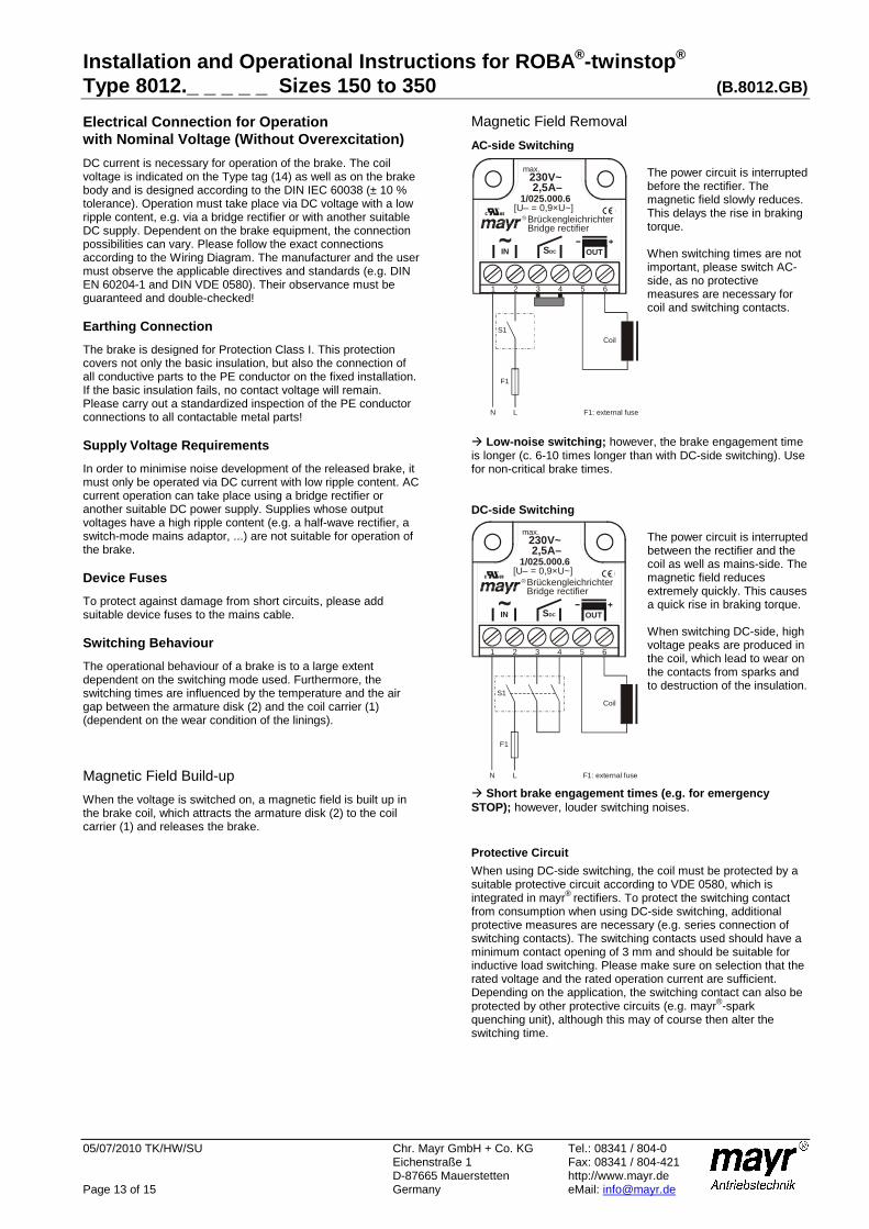
Magnetic Field Removal
AC-side Switching The power circuit is interrupted before the rectifier. The magnetic field slowly reduces. This delays the rise in braking torque. When switching times are not important, please switch AC-side, as no protective measures are necessary for coil and switching contacts.
Low-noise switching; however, the brake engagement time is longer (c. 6-10 times longer than with DC-side switching). Use for non-critical brake times. DC-side Switching
The power circuit is interrupted between the rectifier and the coil as well as mains-side. The magnetic field reduces extremely quickly. This causes a quick rise in braking torque. When switching DC-side, high voltage peaks are produced in the coil, which lead to wear on the contacts from sparks and to destruction of the insulation.
Short brake engagement times (e.g. for emergency STOP); however, louder switching noises.
Protective Circuit
When using DC-side switching, the coil must be protected by a suitable protective circuit according to VDE 0580, which is integrated in mayr® rectifiers. To protect the switching contact from consumption when using DC-side switching, additional protective measures are necessary (e.g. series connection of switching contacts). The switching contacts used should have a minimum contact opening of 3 mm and should be suitable for inductive load switching. Please make sure on selection that the rated voltage and the rated operation current are sufficient. Depending on the application, the switching contact can also be protected by other protective circuits (e.g. mayr®-spark quenching unit), although this may of course then alter the switching time.
1 2 3 4 5 6
230V~max.
2,5A–1/025.000.6
BrückengleichrichterBridge rectifier
IN SDC OUT
[U– = 0,9×U~]
S1
F1
LN F1: external fuse
Coil
1 2 3 4 5 6
230V~max.
2,5A–1/025.000.6
BrückengleichrichterBridge rectifier
IN SDC OUT
[U– = 0,9×U~]
S1
F1
LN F1: external fuse
Coil

Installation and Operational Instructions for ROBA ®-twinstop ® Type 8012._ _ _ _ _ Sizes 150 to 350 (B.8012.GB)
05/07/2010 TK/HW/SU Chr. Mayr GmbH + Co. KG Tel.: 08341 / 804-0 Eichenstraße 1 Fax: 08341 / 804-421 D-87665 Mauerstetten http://www.mayr.de Page 14 of 15 Germany eMail: [email protected]
Electrical Connection for Operation with Overexcitation
DC current is necessary for operation of the brake. The coil voltage is indicated on the Type tag (14) as well as on the brake body and is designed according to the DIN IEC 60038 (± 10 % tolerance). The brake may only be operated with overexcitation (e.g. with a ROBA®-switch fast acting rectifier or phase demodulator). Dependent on the brake equipment, the connection possibilities can vary. Please follow the exact connections according to the Wiring Diagram. The manufacturer and the user must observe the applicable directives and standards (e.g. DIN EN 60204-1 and DIN VDE 0580). Their observance must be guaranteed and double-checked! Earthing Connection
The brake is designed for Protection Class I. This protection covers not only the basic insulation, but also the connection of all conductive parts to the PE conductor on the fixed installation. If the basic insulation fails, no contact voltage will remain. Please carry out a standardized inspection of the PE conductor connections to all contactable metal parts! Device Fuses
To protect against damage from short circuits, please add suitable device fuses to the mains cable. Switching Behaviour
The operational behaviour of a brake is to a large extent dependent on the switching mode used. Furthermore, the switching times are influenced by the temperature and the air gap between the armature disk (2) and the coil carrier (1) (dependent on the wear condition of the linings). Magnetic Field Build-up
When the voltage is switched on, a magnetic field is built up in the brake coil, which attracts the armature disk (2) to the coil carrier (1) and releases the brake. Field Build-up with Normal Excitation
If we energise the magnetic coil with nominal voltage, the coil voltage does not immediately reach its nominal value. The coil inductivity causes the current to increase slowly as an exponential function. Accordingly, the build-up of the magnetic field takes place more slowly and the braking torque drop (curve 1) is also delayed. Field Build-up with Overexcitation
A quicker and safer drop in braking torque is achieved if the coil is temporarily placed under a higher voltage than the nominal voltage, as the current then increases more quickly. Once the brake is released, it is possible to switch over to the nominal voltage (curve 2). The effective capacity may however not be larger than the nominal capacity of the coil. The ROBA®-switch fast acting rectifier works on this principle, which is obligatory for safe operation of this brake.
Magnetic Field Removal
AC-side Switching
The power circuit is interrupted before the rectifier. The magnetic field slowly reduces. This delays the rise in braking torque. When switching times are not important, please switch AC-side, as no protective measures are necessary for coil and switching contacts.
⇒⇒⇒⇒ Low-noise switching; however, the brake engagement time is longer (c. 6-10 times longer than with DC-side switching). Use for non-critical brake times. DC-side Switching
The power circuit is interrupted between the rectifier and the coil as well as mains-side. The magnetic field reduces extremely quickly. This causes a quick rise in braking torque. When switching DC-side, high voltage peaks are produced in the coil, which lead to wear on the contacts from sparks and to destruction of the insulation.
⇒⇒⇒⇒ Short brake engagement times (e.g. for emergency STOP); however, louder switching noises.
Protective Circuit
When using DC-side switching, the coil must be protected by a suitable protective circuit according to VDE 0580, which is integrated in mayr® rectifiers. To protect the switching contact from consumption when using DC-side switching, additional protective measures are necessary (e.g. series connection of switching contacts). The switching contacts used should have a minimum contact opening of 3 mm and should be suitable for inductive load switching. Please make sure on selection that the rated voltage and the rated operation current are sufficient. Depending on the application, the switching contact can also be protected by other protective circuits (e.g. mayr®-spark quenching unit), although this may of course then alter the switching times.
F1: External fuse
CoilS1
F1
LN
1 2 3 4 5 6 7 8
1 2 3 4 5 6 7 8
20/017.000.2
200 - 500V~
200 - 300V~ :R
IN OUT
U– = 0,45×U~
+–SDC
ROBA -switch
I = 1,8Amax –
0,05-2sec
0 -10MΩ Ω
t:
R R
F1: External fuse
CoilS1
F1
LN
1 2 3 4 5 6 7 8
1 2 3 4 5 6 7 8
20/017.000.2
200 - 500V~
200 - 300V~ :R
IN OUT
U– = 0,45×U~
+–S DC
ROBA -switch
I = 1,8Amax –
0,05-2sec
0 -10MΩ Ω
t:
R R
1
t
1
t
2
2I MBraking torque path
Mnom
Inom
Current path
Installation and Operational Instructions for ROBA ®-twinstop ® Type 8012._ _ _ _ _ Sizes 150 to 350 (B.8012.GB)
05/07/2010 TK/HW/SU Chr. Mayr GmbH + Co. KG Tel.: 08341 / 804-0 Eichenstraße 1 Fax: 08341 / 804-421 D-87665 Mauerstetten http://www.mayr.de Page 15 of 15 Germany eMail: [email protected]
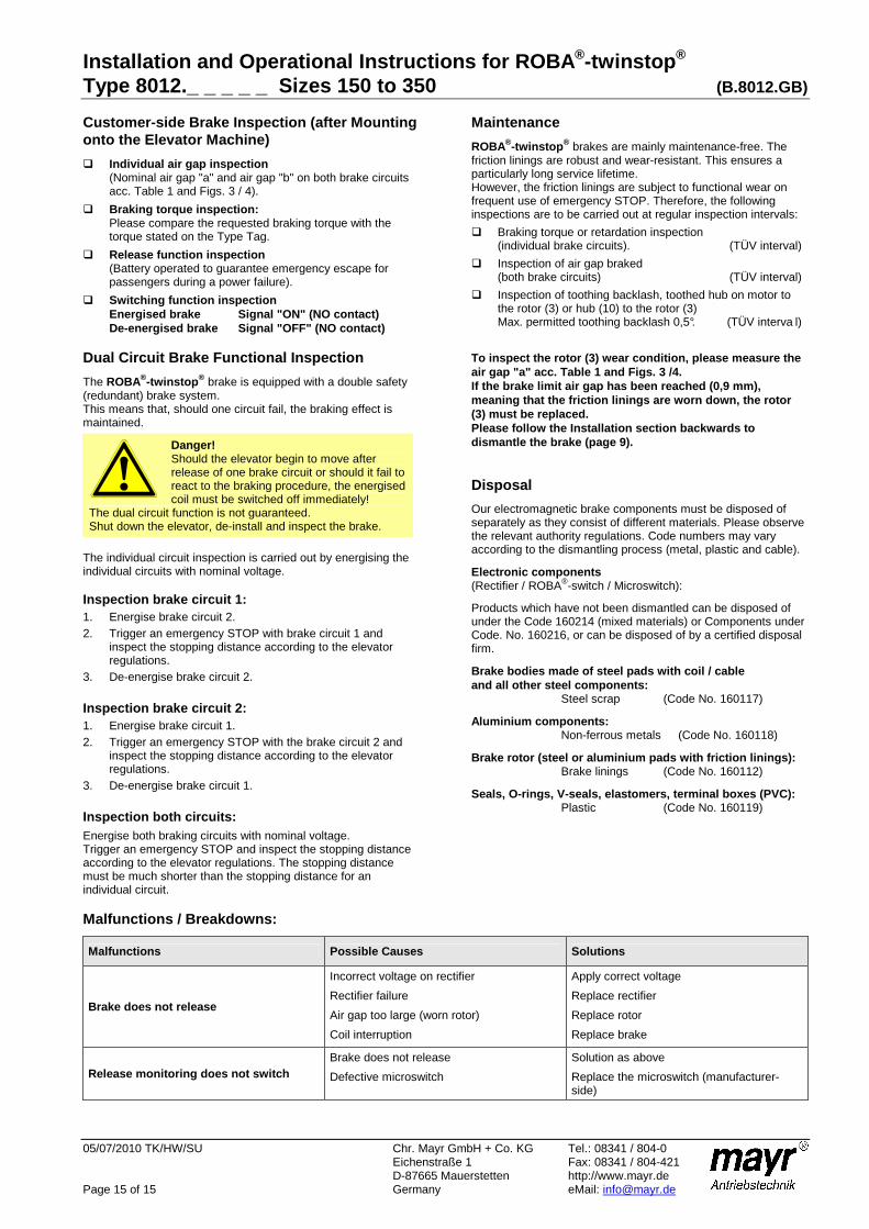
Customer-side Brake Inspection (after Mounting onto the Elevator Machine)
Individual air gap inspection (Nominal air gap "a" and air gap "b" on both brake circuits acc. Table 1 and Figs. 3 / 4).
Braking torque inspection: Please compare the requested braking torque with the torque stated on the Type Tag.
Release function inspection (Battery operated to guarantee emergency escape for passengers during a power failure).
Switching function inspection Energised brake Signal "ON" (NO contact) De-energised brake Signal "OFF" (NO contact)
Dual Circuit Brake Functional Inspection
The ROBA®-twinstop ® brake is equipped with a double safety (redundant) brake system. This means that, should one circuit fail, the braking effect is maintained.
Danger! Should the elevator begin to move after release of one brake circuit or should it fail to react to the braking procedure, the energised coil must be switched off immediately!
The dual circuit function is not guaranteed. Shut down the elevator, de-install and inspect the brake.
The individual circuit inspection is carried out by energising the individual circuits with nominal voltage. Inspection brake circuit 1: 1. Energise brake circuit 2. 2. Trigger an emergency STOP with brake circuit 1 and
inspect the stopping distance according to the elevator regulations.
3. De-energise brake circuit 2. Inspection brake circuit 2: 1. Energise brake circuit 1. 2. Trigger an emergency STOP with the brake circuit 2 and
inspect the stopping distance according to the elevator regulations.
3. De-energise brake circuit 1. Inspection both circuits: Energise both braking circuits with nominal voltage. Trigger an emergency STOP and inspect the stopping distance according to the elevator regulations. The stopping distance must be much shorter than the stopping distance for an individual circuit.
Maintenance
ROBA®-twinstop ® brakes are mainly maintenance-free. The friction linings are robust and wear-resistant. This ensures a particularly long service lifetime. However, the friction linings are subject to functional wear on frequent use of emergency STOP. Therefore, the following inspections are to be carried out at regular inspection intervals:
Braking torque or retardation inspection (individual brake circuits). (TÜV interval)
Inspection of air gap braked (both brake circuits) (TÜV interval)
Inspection of toothing backlash, toothed hub on motor to the rotor (3) or hub (10) to the rotor (3) Max. permitted toothing backlash 0,5°. (TÜV interva l)
To inspect the rotor (3) wear condition, please mea sure the air gap "a" acc. Table 1 and Figs. 3 /4. If the brake limit air gap has been reached (0,9 mm ), meaning that the friction linings are worn down, th e rotor (3) must be replaced. Please follow the Installation section backwards to dismantle the brake (page 9). Disposal
Our electromagnetic brake components must be disposed of separately as they consist of different materials. Please observe the relevant authority regulations. Code numbers may vary according to the dismantling process (metal, plastic and cable).
Electronic components (Rectifier / ROBA®-switch / Microswitch):
Products which have not been dismantled can be disposed of under the Code 160214 (mixed materials) or Components under Code. No. 160216, or can be disposed of by a certified disposal firm.
Brake bodies made of steel pads with coil / cable and all other steel components: Steel scrap (Code No. 160117)
Aluminium components: Non-ferrous metals (Code No. 160118)
Brake rotor (steel or aluminium pads with friction linings): Brake linings (Code No. 160112)
Seals, O-rings, V-seals, elastomers, terminal boxes (PVC): Plastic (Code No. 160119)
Malfunctions / Breakdowns:
Malfunctions Possible Causes Solutions
Brake does not release
Incorrect voltage on rectifier
Rectifier failure
Air gap too large (worn rotor)
Coil interruption
Apply correct voltage
Replace rectifier
Replace rotor
Replace brake
Release monitoring does not switch Brake does not release
Defective microswitch
Solution as above
Replace the microswitch (manufacturer-side)