Installation And Operation Manual - navalex.comnavalex.com/downloads/Tranter_Supermax_IOM.pdf ·...
20
Installation And Operation Manual SUPERMAX ® SHELL & PLATE HEAT EXCHANGER www.tranter.com
Transcript of Installation And Operation Manual - navalex.comnavalex.com/downloads/Tranter_Supermax_IOM.pdf ·...
Installation And Operation Manual
SUPERMAX®
SHELL & PLATE HEAT EXCHANGER
www.tranter.com
2
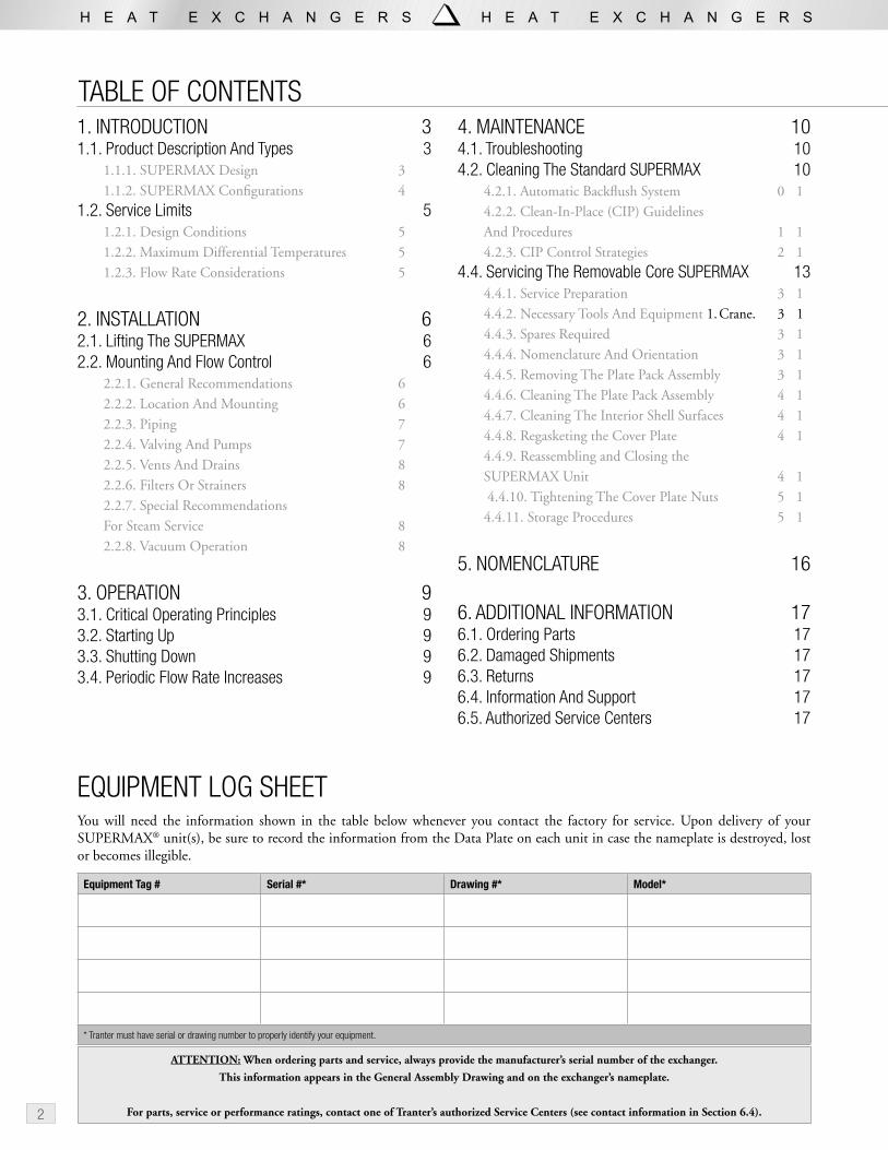
EQUIPMENT LOG SHEETYou will need the information shown in the table below whenever you contact the factory for service. Upon delivery of your SUPERMAX® unit(s), be sure to record the information from the Data Plate on each unit in case the nameplate is destroyed, lost or becomes illegible.
Equipment Tag # Serial #* Drawing #* Model*
* Tranter must have serial or drawing number to properly identify your equipment.
ATTENTION: When ordering parts and service, always provide the manufacturer’s serial number of the exchanger.
This information appears in the General Assembly Drawing and on the exchanger’s nameplate.
For parts, service or performance ratings, contact one of Tranter’s authorized Service Centers (see contact information in Section 6.4).
TABLE OF CONTENTS1. INTRODUCTION 31.1. Product Description And Types 3
1.1.1. SUPERMAX Design 31.1.2. SUPERMAX Configurations 4
1.2. Service Limits 51.2.1. Design Conditions 51.2.2. Maximum Differential Temperatures 51.2.3. Flow Rate Considerations 5
2. INSTALLATION 62.1. Lifting The SUPERMAX 62.2. Mounting And Flow Control 6
2.2.1. General Recommendations 62.2.2. Location And Mounting 62.2.3. Piping 72.2.4. Valving And Pumps 72.2.5. Vents And Drains 82.2.6. Filters Or Strainers 82.2.7. Special Recommendations For Steam Service 82.2.8. Vacuum Operation 8
3. OPERATION 93.1. Critical Operating Principles 93.2. Starting Up 93.3. Shutting Down 93.4. Periodic Flow Rate Increases 9
4. MAINTENANCE 104.1. Troubleshooting 104.2. Cleaning The Standard SUPERMAX 10
4.2.1. Automatic Backflush System 104.2.2. Clean-In-Place (CIP) Guidelines And Procedures 114.2.3. CIP Control Strategies 12
4.4. Servicing The Removable Core SUPERMAX 134.4.1. Service Preparation 134.4.2. Necessary Tools And Equipment 1. Crane. 134.4.3. Spares Required 134.4.4. Nomenclature And Orientation 134.4.5. Removing The Plate Pack Assembly 134.4.6. Cleaning The Plate Pack Assembly 144.4.7. Cleaning The Interior Shell Surfaces 144.4.8. Regasketing the Cover Plate 144.4.9. Reassembling and Closing the SUPERMAX Unit 14 4.4.10. Tightening The Cover Plate Nuts 154.4.11. Storage Procedures 15
5. NOMENCLATURE 16
6. ADDITIONAL INFORMATION 176.1. Ordering Parts 176.2. Damaged Shipments 176.3. Returns 176.4. Information And Support 176.5. Authorized Service Centers 17
3
1.1. Product Description And Types
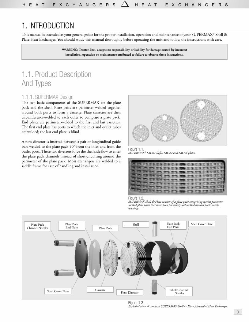
1.1.1. SUPERMAX DesignThe two basic components of the SUPERMAX are the plate pack and the shell. Plate pairs are perimeter-welded together around both ports to form a cassette. Plate cassettes are then circumference-welded to each other to comprise a plate pack. End plates are perimeter-welded to the first and last cassettes. The first end plate has ports to which the inlet and outlet tubes are welded; the last end plate is blind.
A flow director is inserted between a pair of longitudinal guide bars welded to the plate pack 90° from the inlet and from the outlet ports. These two diverters force the shell side flow to enter the plate pack channels instead of short-circuiting around the perimeter of the plate pack. Most exchangers are welded to a saddle frame for ease of handling and installation.
Figure 1.1.SUPERMAX® SM-07 (left), SM-22 and SM-54 plates.
1. INTRODUCTIONThis manual is intended as your general guide for the proper installation, operation and maintenance of your SUPERMAX® Shell & Plate Heat Exchanger. You should study this manual thoroughly before operating the unit and follow the instructions with care.
WARNING: Tranter, Inc., accepts no responsibility or liability for damage caused by incorrect
installation, operation or maintenance attributed to failure to observe these instructions.
Figure 1.2.SUPERMAX Shell & Plate consists of a plate pack comprising special perimeter welded plate pairs that have been previously seal welded around plate nozzle openings.
Figure 1.3.Exploded view of standard SUPERMAX Shell & Plate All-welded Heat Exchanger.
Shell Cover Plate
Plate Pack End Plate
Shell Channel Nozzles
Cassette
Plate PackPlate PackEnd Plate
Plate Pack Channel Nozzles
Shell Cover PlateShell
Flow Director

4
1.1.2. SUPERMAX ConfigurationsThe SUPERMAX is available in SM-07, SM-22 and SM-54 models. The SM-07 has a maximum plate side nozzle size of DN 50 (2 in.); the SM-22 DN 100 (4 in.) and the SM-54 DN 150 (6 in.).
The Standard SUPERMAX constitutes a welded pressure vessel of high integrity. The standard unit is not designed for access or cleaning by mechanical means.
The Removable Core SUPERMAX exchanger (available as an option in all sizes) is fully accessible for inspection and/or mechanical cleaning by removing the cover plate assembly. A full-face, flat-flange gasket is installed between the plate pack assembly cover and the shell assembly flange.
Figure 1.5.The SUPERMAX is available in SM-22, SM-07 and SM-54 models. The exchangers are shown in their standard configurations.
Figure 1.4.Exploded view of Removable Core SUPERMAX Shell & Plate All-Welded Heat Exchanger.
The Two-In-One SUPERMAX has two separate plate packs that share one shell. These cores can handle different or identical fluids. For flows that require a high flow rate and a short residence time (low hold-up volume), dual inlets and outlets can be piped together by means of special manifold options.
Figure 1.7.Two independent plate packs share a common shell in the Two-In-One SUPERMAX.
Figure 1.6.A SUPERMAX can be configured to handle higher flow rates by adding dual inlets/outlets and an engineered half-pipe manifold.
1. INTRODUCTION (continued)

5
The Multipass SUPERMAX offers multiple passes through separate plate pack zones on both the plate and shell sides, with countercurrent fl ow through both passes. The unit has two plate pack units separated by a special one-port divider plate that directs the fl ow from the fi rst pack into the second and changes its direction by 180°. Inlet and outlet ports are at opposite ends of the unit. The shell includes a special fl ow director that directs the shell-side fl ow through one plate pack and then the other.
1.2. Service Limits
1.2.1. Design ConditionsDesign operating conditions for each SUPERMAX heat exchanger appear stamped on the exchanger’s nameplate (see Figure 1.9.) and are shown on the general arrangement drawing furnished with the unit. The SUPERMAX exchanger should never be operated under conditions that exceed those stamped on the nameplate.
1.2.2. Maximum Differential TemperaturesSUPERMAX Shell & Plate Heat Exchanger is limited to a maximum differential temperature (hot fl uid inlet temperature minus cold fl uid inlet temperature) of 230°C (450°F). Exceeding this limitation may result in thermal fatigue damage to the equipment.
1.2.3. Flow Rate ConsiderationsOperating fl ow rates should be maintained as close as possible to the design fl ow rates. Flow rates lower than the original design may result in premature fouling.
Figure 1.8.The Multipass SUPERMAX has a divided plate pack channel to comprise two countercurrent zones.
���������������������������������������������������������������������������������������
�
������
�����
����������
��� ���
������
������
����
�������������
�������������
�
�
�
�����������������������
���������������������������������
�������������
�
���
���
���
���
��
��
��
��
Figure 1.9.Do not operate the SUPERMAX under conditions that exceed those stamped on the nameplate.

6
2. INSTALLATION
2.1. Lifting The SUPERMAXTo lift SUPERMAX Shell & Plate units, use the lifting lugs provided for that purpose on the top of the front and rear cover plates. Do not use the pulling lug on the removable cover plate (if installed) to lift the entire unit.
WARNING: Never lift the exchanger by the nozzles or apply any forces to the connections
while lifting.
Figure 2.1.Lifting the SUPERMAX exchanger using the lifting lugs. Do not lift the SUPERMAX by the inlet or outlet nozzles.
2.2. Mounting And Flow Control
2.2.1. General RecommendationsAlways follow generally accepted piping and equipment control practices. Observing the following recommendations will help ensure long operating life and trouble-free maintenance.
Mounting recommendations are intended for a horizontal mounting configuration. Vertical mounting is only recommended on a case-by-base basis. Contact the factory for assistance in case vertical mounting is desired.
2.2.2. Location And Mounting1. Locate the exchanger in an area free of congestion with
piping or other equipment.
2. Provide approximately 600 mm (2 ft) of clearance along each side of the unit to allow access to the connections.
3. For removable core models, be sure to leave sufficient clearance at the plate pack nozzle end (at least equal to the overall length of the unit) to enable interference-free removal of the core.
4. Use shims as necessary to level the heat exchanger.
5. Mount the unit securely to the foundation using anchor bolts.
Figure 2.2.Mount the SUPERMAX securely using leveling shims as necessary and anchor bolts. Provide approximately 600 mm (2 ft) of service clearance on either side.
Shims As Necessary
Anchor Bolts
Clearance600 mm (2 ft)

7
Figure 2.3.Follow piping recommendations to prevent stress on connections and enable efficient servicing.
No More Than 2 m (78 in.) From
Connections
Removable For Servicing Plate Pack
Assembly
2.2.3. Piping 1. Consult Table 2.1. to avoid overloading nozzles during
installation and in the completed configuration
2. Avoid long, straight piping runs in the inlet and outlet approaches.
3. Employ elbows and expansion couplings to accommodate thermal expansion, pulsation and hydrodynamic shock that could damage the exchanger or its nozzles.
4. Position pipe supports no more than 2 m (78 in.) from the connections to prevent stress on the connection nozzles.
5. For removable core models, plan for removal of the approach piping downstream of the shut-off valves to enable pulling of the plate pack assembly without interference.
2.2.4. Valving And Pumps1. To prevent water hammer, two-stage valves or slow-acting,
throttling-capable valves should be used.
2. Globe or butterfly valves are recommended; these should be maintained in good working order.
3. Control sequences should be planned to prevent thermal or mechanical stresses from occurring during start-up and transition operating phases.
4. Pumps serving the heat exchanger should be equipped with throttling valves.
5. When the maximum pump discharge pressure exceeds the maximum design pressure of the exchanger, a pressure reducing valve should be installed at the exchanger inlets.
6. Positive displacement pumps (especially reciprocating pumps) should be equipped with vibration dampers to minimize harmonics and pulsation.
7. Positive displacement pumps should be equipped with a pressure relief valve on the pump discharge side.
Force
Nozzle, DN (ANSI RF)
Direct comp-ression, N (lb)
Radial force, N (lb)
Torsion moment, Nm (ft lb)
Bending moment, Nm (ft lb)
25 (1) 90 (20) 90 (20) 0 (0) 0 (0)
38 (1.5) 159 (36) 159 (36) 37 (27) 37 (27)
50 (2) 208 (47) 208 (47) 76 (56) 76 (56)
65 (2.5) 287 (65) 287 (65) 153 (112) 153 (112)
80 (3) 365 (82) 365 (82) 230 (169) 230 (169)
100 (4) 477 (107) 477 (107) 358 (264) 358 (264)
150 (6) 776 (175) 776 (175) 750 (553) 750 (553)
200 (8) 1096 (246) 1096 (246) 1236 (911) 1236 (911)
250 (10) 1433 (322) 1433 (322) 1809 (1335) 1809 (1335)
300 (12) 1784 (401) 1784 (401) 2471 (1822) 2471 (1822)
Table 2.1. Maximum Nozzle Loading
Source: API 662, Standard Service.

8
2.2.5. Vents And DrainsVents and drains are standard on multi-pass units and all units where the application involves gases, noncondensable gases, refrigerants or two-phase flow. In these applications, always connect the vent and drain couplings to the draining and venting circuits through valves. The vent valve should always be open, allowing continuous self-venting.
2.2.6. Filters Or StrainersThe plate pack channel is designed for use with clear fluids; thus, fibers or particulate matter can plug this channel. External filters or strainers should be used when solids are present. Contact your factory representative to determine proper filtration procedures/devices.
2.2.7. Special Recommendations For Steam Service1. Install moisture separators, pressure relief valves and float
& thermostatic (F&T) steam traps to prevent condensate accumulation in the plate pack channels. This will protect the exchanger from possible water hammer damage.
2. When the unit is operating with vacuum or partial-vacuum steam, condensate pumps should be used to prevent backflow of condensate into the exchanger and system-induced “stall” conditions.
3. Vacuum breakers should be installed at the plate pack channel inlet to prevent condensate backflow into the plate due to the vacuum produced by condensation of steam during shut-down.
4. If the SUPERMAX is used as a steam condenser, control the process on the steam side. If it must be controlled on the condensate side, the condensate control valve should operate within 80–110% of its range to avoid “on/off ” cycling.
2.2.8. Vacuum OperationIf the SUPERMAX exchanger will operate under either constant or intermittent vacuum (e.g., under upset conditions), make sure that the circuit of concern is rated for full vacuum as indicated on the Application Data Sheet and drawing. Install a vacuum break at the outlets to prevent liquid backflow and water hammer problems.
Figure 2.4.Vents, or vapor break fittings, are provided for two-phase flow and noncondensable gas applications. Be sure to install vacuum breakers during installation.
������������
PLC
T
���������
������������������������������
������������������
����������������
��������
����������
�������
����������
�������������������������������
���������
Figure 2.5.Correctly engineered condensate handling will prevent system-induced “stall” conditions, protect equipment from damage, improve thermal control and save energy.
2. INSTALLATION (continued)
Vapor Break Connections
WARNING: Your SUPERMAX guarantee may become void if vents
are not employed with channels involving fluids that can generate
gases, e.g., in most feed/bottom heat recovery where the cold stream
generally releases trapped and/or dissolved gas.

9
3.1. Critical Operating PrinciplesAll operators should familiarize themselves with the following operating principles, which are critical in preventing damage.
1. Water hammer, if suspected, must be diagnosed and eliminated, or damage may result to the SUPERMAX.
2. Pumps should always be started against closed valves.
3. Valves must be set to open gradually. Sudden opening and closing of the valves will subject the exchanger to mechanical and thermal shock and may cause material fatigue.
4. Starting up and shutting down should be managed to minimize differential expansion between the plate pack and shell assemblies. Always follow the stated steps in order.
5. The maximum temperature rise measured at the hot channel outlet should be no more than approximately 30°C (55°F) per min. The temperature rise should be as slow as possible.
3.2. Starting Up1. Inspect the unit carefully. For removable core units, ensure
that the cover plate nuts are properly torqued (see Section 4.4.10.)
2. After extended storage or time off-line, ensure that the approach piping to the plate pack channel is free of scale or contamination that may clog the fluid passages
3. Make sure that all inlet and outlet connections are tight.
4. Always establish the cold side flow first, then the hot side flow.
5. Make sure the cold side inlet valve between the pump and SUPERMAX unit is closed.
6. Fully open the shut-off valve at the outlet (if one was installed).
7. Open the vent valve to evacuate air, then start the pump.
8. Slowly open the feed valve. Close the vent valve when all air has been removed.
9. Wait several minutes, then repeat Steps 5–8 for the hot side, taking approximately 5 min. to fully open the inlet valve. The maximum temperature rise measured at the hot channel outlet should be no more than approximately 30°C (55°F) per min. The temperature rise should be as slow as possible.
Figure 3.1.Always start the cold side first, then the hot side.
3. OPERATION
3.3. Shutting DownFollow Steps 1–4 for the hot side first, then repeat the procedure for the cold side. Always decrease the flow to the hot side until closed. Then shut down the cold side flow.
1. Slowly close the hot side inlet valves.
2. Switch off the pump.
3. Close the outlet valves.
4. Drain and vent the unit.
5. Repeat Steps 1–4 for the cold side.
3.4. Periodic Flow Rate IncreasesThe rate of heat transfer surface fouling is affected by fluid velocity. Tranter recommends that the flow rate be increased if possible at regular intervals. The increased turbulence within the channel will retard the rate of fouling. The frequency and duration of this preventive cleaning practice will vary depending on operating fluid velocities and fouling tendencies of the medium.
CAUTION: In steam applications, never leave the steam on with the
liquid side turned off. Turn the steam off first and on last.
1. Establish Cold Channel Flow
2. Establish Steam Flow
Figure 3.2.Always shut down the hot side first, then the cold side.
2. Shut Off Cold Channel Flow
1. Shut Off Steam Flow
10
4. MAINTENANCE
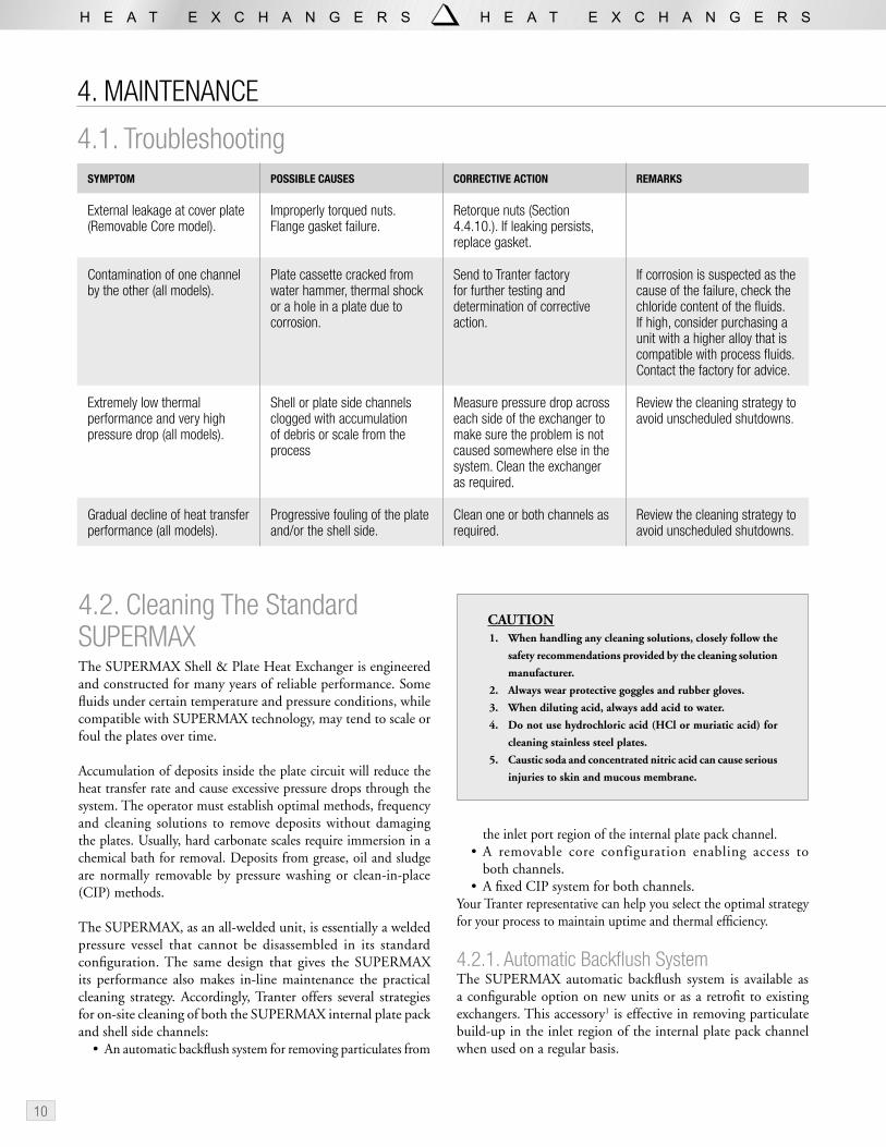
4.1. TroubleshootingSYMPTOM POSSIBLE CAUSES CORRECTIVE ACTION REMARKS
External leakage at cover plate (Removable Core model).
Improperly torqued nuts. Flange gasket failure.
Retorque nuts (Section 4.4.10.). If leaking persists, replace gasket.
Contamination of one channel by the other (all models).
Plate cassette cracked from water hammer, thermal shock or a hole in a plate due to corrosion.
Send to Tranter factory for further testing and determination of corrective action.
If corrosion is suspected as the cause of the failure, check the chloride content of the fluids. If high, consider purchasing a unit with a higher alloy that is compatible with process fluids.Contact the factory for advice.
Extremely low thermal performance and very high pressure drop (all models).
Shell or plate side channels clogged with accumulation of debris or scale from the process
Measure pressure drop across each side of the exchanger to make sure the problem is not caused somewhere else in the system. Clean the exchanger as required.
Review the cleaning strategy to avoid unscheduled shutdowns.
Gradual decline of heat transfer performance (all models).
Progressive fouling of the plate and/or the shell side.
Clean one or both channels as required.
Review the cleaning strategy to avoid unscheduled shutdowns.
4.2. Cleaning The Standard SUPERMAXThe SUPERMAX Shell & Plate Heat Exchanger is engineered and constructed for many years of reliable performance. Some fluids under certain temperature and pressure conditions, while compatible with SUPERMAX technology, may tend to scale or foul the plates over time.
Accumulation of deposits inside the plate circuit will reduce the heat transfer rate and cause excessive pressure drops through the system. The operator must establish optimal methods, frequency and cleaning solutions to remove deposits without damaging the plates. Usually, hard carbonate scales require immersion in a chemical bath for removal. Deposits from grease, oil and sludge are normally removable by pressure washing or clean-in-place (CIP) methods.
The SUPERMAX, as an all-welded unit, is essentially a welded pressure vessel that cannot be disassembled in its standard configuration. The same design that gives the SUPERMAX its performance also makes in-line maintenance the practical cleaning strategy. Accordingly, Tranter offers several strategies for on-site cleaning of both the SUPERMAX internal plate pack and shell side channels:
• An automatic backflush system for removing particulates from
the inlet port region of the internal plate pack channel.• A removable core configuration enabling access to
both channels.• A fixed CIP system for both channels.
Your Tranter representative can help you select the optimal strategy for your process to maintain uptime and thermal efficiency.
4.2.1. Automatic Backflush SystemThe SUPERMAX automatic backflush system is available as a configurable option on new units or as a retrofit to existing exchangers. This accessory1 is effective in removing particulate build-up in the inlet region of the internal plate pack channel when used on a regular basis.
CAUTION1. When handling any cleaning solutions, closely follow the
safety recommendations provided by the cleaning solution
manufacturer.
2. Always wear protective goggles and rubber gloves.
3. When diluting acid, always add acid to water.
4. Do not use hydrochloric acid (HCl or muriatic acid) for
cleaning stainless steel plates.
5. Caustic soda and concentrated nitric acid can cause serious
injuries to skin and mucous membrane.

11
If the backflushing flow rate can be increased above the operational flow rate, some particulate can be flushed from the plate pack internal channels. It is not recommended as a strategy for dealing with biofouling. Exchangers handling flows containing particulates larger than 1 mm (0.039 in.) should be equipped with porthole strainers or an upstream filtration system capable of removing this material.
The backflush valve itself bolts directly to the inlet/outlet flanges of the SUPERMAX. A double-acting pneumatic actuator shifts the rotary four-way valve. During normal operation, the internal plate pack channel fluid passes straight through. In the backflushing cycle, the pneumatic actuator rotates the valve plug to reverse flow through the internal plate pack channel. Tranter recommends inclusion of an automatic dump valve (not included) synchronized with the backflush valve to remove the washings from the process lines.
The automatic backflush system is durable and easy to maintain. A removable cover allows access to valve internals without removing the valve from process piping. Stainless steel internals and a neoprene rubber seal are designed to provide long service cycles and trouble-free operation.
Figure 4.1.SUPERMAX Shell & Plate Heat Exchanger with backflush valve installed.
1Available from Water Technology of Pensacola. Inc., 3000 West Nine Mile Rd., Pensacola, Florida 32534-9439; tel. (800) 282-7978, Email [email protected], Web http://www.atbsystems.com/.
Inlet
Outlet
Washings
To EffluentTreatment
Shell SideInlet
Shell SideOutlet
AutomaticBackflush
Valve
NormalOperation
FromProcess
ToProcess
PLC
Figure 4.2.SUPERMAX Shell & Plate Heat Exchanger with backflush valve during normal process operation.
Inlet
Outlet
Washings
To EffluentTreatment
Shell SideInlet
Shell SideOutlet
AutomaticBackflush
Valve
BackflushingCycle
FromProcess
ToProcess
PLC
Figure 4.3.SUPERMAX Shell & Plate Heat Exchanger with backflush valve during backflushing cycle.
4.2.2. Clean-In-Place (CIP) Guidelines And Procedures1. Drain both channels and flush the process circuit with cold, fresh
water. If the cooling circuit uses seawater, flush this channel also.
2. Flush both channels with warm water, 40–50°C (100–120°F), until the effluent water is clear.
3. When mixing the cleaning solution, use chloride-free or low chloride water with a low hardness value.

12
4. MAINTENANCE (continued)
TYPE OF FOULING SUGGESTED CLEANERS
Calcium sulphate, silicates Citric, nitric, phosphoric or sulfamic acid
Calcium carbonate 10% nitric acid (1 volume concentrated nitric acid with specific gravity 1.41 to 9 volumes of water), Oakite 131
Alumina, metal oxides, silt Citric, nitric, phosphoric, or sulfamic acid (To improve cleaning add detergent to acid.)
Barnacles, mussels, seaweed, wood chips Back flush per cleaning-in-place procedure below
Biological growth Sodium carbonate or sodium hydroxide
Table 4.1 CIP Cleaning Solutions
4. If possible, pump the cleaning solution opposite the normal flow direction for back-flushing action.
5. Pump the cleaning solution at flow rates up to 1.5 times the normal working flow rate, where possible, without exceeding the maximum nozzle velocity of 8.5 m/sec (28 ft/sec).
If high CIP flow rates cannot be attained, use a solution capable of dissolving deposits at lower flow rates and/or lengthen the CIP cleaning cycle.
Figure 4.4.Basic CIP configuration for one SUPERMAX channel, showing isolation valves and countercurrent cleaning.
Figure 4.5.The elements of a CIP system under pH control.
pH
Process Out
Process In
CIP Cleaning Solution Tank
Monitoring Probe
Self-Priming Pump
Process Out
Cleaning Solution In
Cleaning Solution Out
Process In
6. Hydraulic shock must be avoided; use centrifugal CIP pumps that can attain the CIP flow rate and operating pressure gradually.
7. After completing the cleaning cycle, flush the exchanger and approach piping with clean water.
4.2.3. CIP Control StrategiesProgrammable Logic Controllers (PLCs) may be used to manage either the CIP process using a choice of several strategies, including:
• Timed backflushing events (hourly, daily, etc.)
• Differential pressure across plate pack
• Differential temperature across plate pack
The differential methods require optional transducers and establishment of a differential setpoint that, when exceeded, initiates a single or multiple cleaning cycles that loop until the differential widens to clean or near-clean conditions.
CAUTION: Always add cleaning solution concentrates to the
dilution water and mix well before circulation begins.
13
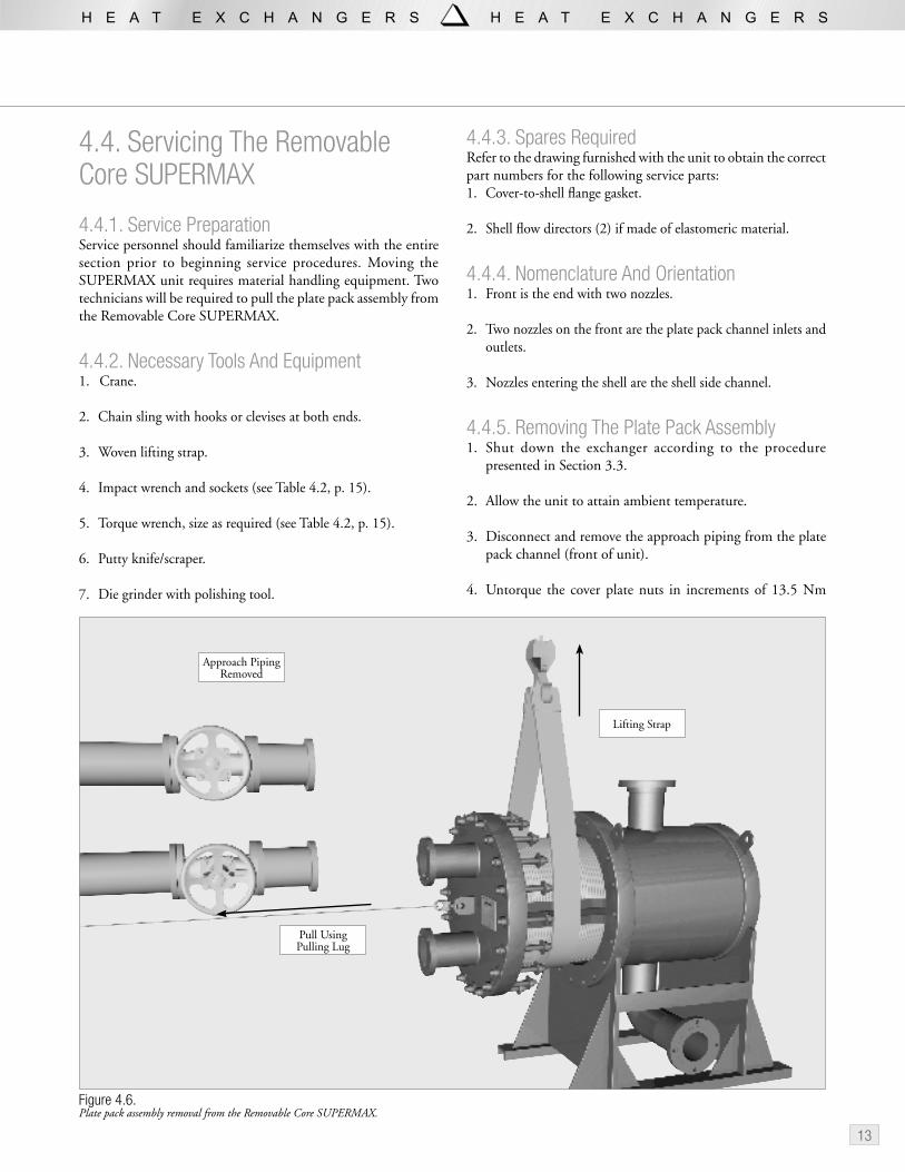
4.4. Servicing The Removable Core SUPERMAX
4.4.1. Service PreparationService personnel should familiarize themselves with the entire section prior to beginning service procedures. Moving the SUPERMAX unit requires material handling equipment. Two technicians will be required to pull the plate pack assembly from the Removable Core SUPERMAX.
4.4.2. Necessary Tools And Equipment 1. Crane.
2. Chain sling with hooks or clevises at both ends.
3. Woven lifting strap.
4. Impact wrench and sockets (see Table 4.2, p. 15).
5. Torque wrench, size as required (see Table 4.2, p. 15).
6. Putty knife/scraper.
7. Die grinder with polishing tool.
4.4.3. Spares Required Refer to the drawing furnished with the unit to obtain the correct part numbers for the following service parts:1. Cover-to-shell flange gasket.
2. Shell flow directors (2) if made of elastomeric material.
4.4.4. Nomenclature And Orientation1. Front is the end with two nozzles.
2. Two nozzles on the front are the plate pack channel inlets and outlets.
3. Nozzles entering the shell are the shell side channel.
4.4.5. Removing The Plate Pack Assembly1. Shut down the exchanger according to the procedure
presented in Section 3.3.
2. Allow the unit to attain ambient temperature.
3. Disconnect and remove the approach piping from the plate pack channel (front of unit).
4. Untorque the cover plate nuts in increments of 13.5 Nm
Figure 4.6.Plate pack assembly removal from the Removable Core SUPERMAX.
Approach Piping Removed
Lifting Strap
Pull Using Pulling Lug
14
4.4.6. Cleaning The Plate Pack AssemblyClean the internal plate pack and shell side channel passages by one of several methods, including:
• Pressure washing (sediments, grease, sludge)• Solvent bath (hard scale)• Ultrasonic bath
For pressure washing, apply a nozzle pressure of no greater than 240 bar (3500 psi). Direct the wash stream down the shell side channels, both inlet and outlet. A steam-heated washdown station can also be effective in removing some types of deposits.
The ultrasonic bath can be particularly effective, since the impact force of the solution reaches all internal surfaces.
Solvent baths usually involve use of dilute mineral acid or alkali, or both, usually heated, with each immersion followed by a water rinse.
4.4.7. Cleaning The Interior Shell SurfacesThe SUPERMAX shell should be cleaned with fi ber brushes. Do not use wire brushes to clean any internal surfaces.
4.4.8. Regasketing the Cover PlateRefer to the SUPERMAX drawing furnished with the unit to secure the appropriate blind fl ange gasket material.
1. Clean the cover plate and shell fl ange gasket lands thoroughly. Remove any gasket fragments and residue.
2. Inspect the surface of the gasket lands for scratches, impact marks or foreign material on it. Polish any imperfections.
3. With the lands clean and dry, position the gasket in the shell fl ange land.
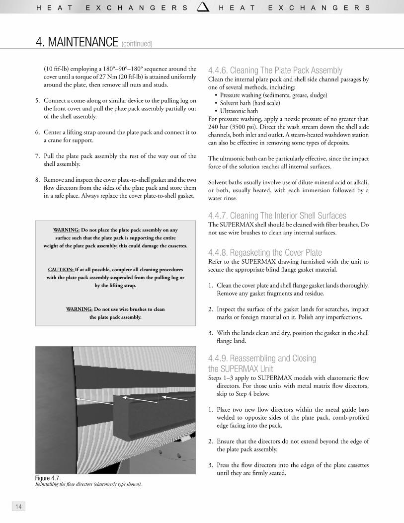
4.4.9. Reassembling and Closing the SUPERMAX UnitSteps 1–3 apply to SUPERMAX models with elastomeric fl ow
directors. For those units with metal matrix fl ow directors, skip to Step 4 below.
1. Place two new fl ow directors within the metal guide bars welded to opposite sides of the plate pack, comb-profi led edge facing into the pack.
2. Ensure that the directors do not extend beyond the edge of the plate pack assembly.
3. Press the fl ow directors into the edges of the plate cassettes until they are fi rmly seated.
WARNING: Do not place the plate pack assembly on any
surface such that the plate pack is supporting the entire
weight of the plate pack assembly; this could damage the cassettes.
CAUTION: If at all possible, complete all cleaning procedures
with the plate pack assembly suspended from the pulling lug or
by the lifting strap.
WARNING: Do not use wire brushes to clean
the plate pack assembly.
Figure 4.7.Reinstalling the fl ow directors (elastomeric type shown).
4. MAINTENANCE (continued)
(10 ftf-lb) employing a 180°–90°–180° sequence around the cover until a torque of 27 Nm (20 ftf-lb) is attained uniformly around the plate, then remove all nuts and studs.
5. Connect a come-along or similar device to the pulling lug on the front cover and pull the plate pack assembly partially out of the shell assembly.
6. Center a lifting strap around the plate pack and connect it to a crane for support.
7. Pull the plate pack assembly the rest of the way out of the shell assembly.
8. Remove and inspect the cover plate-to-shell gasket and the two fl ow directors from the sides of the plate pack and store them in a safe place. Always replace the cover plate-to-shell gasket.

15
4. Raise the plate pack assembly horizontally using the lifting strap around the plate pack assembly.
5. Position the plate pack assembly so that it begins to enter the bore of the shell assembly and the dogs on the rear end plate are helping to support the unit.
6. Remove the lifting strap, while supporting the unit by the cover plate. Slide the assembly into the shell.
7. Rotate the plate pack assembly within the shell assembly as necessary so that the registration marks on the cover plate edge and shell flange edge align.
4.4.10. Tightening The Cover Plate Nuts1. Insert the cover studs through the cover plate and shell flange
holes. Install the nuts on both ends.
2. Torque the cover plate nuts in increments of 28 Nm (20 ftf-lb) employing a 180°–90°–180° sequence around the cover until the specified torque (Table 4.2) is attained uniformly around the plate.
Removable Core SUPERMAX Torque ChartMODEL PRESSURE
CLASSBOLT SIZE, SAE in. (mm)
TORQUE, Nm (ftf-lb)
SM-07 H 1 (25) 335 (245)
U 1-1/8 (29) 480 (355)
S 1-1/4 (32) 675 (500)
SM-22 H 1-1/4 (32) 675 (500)
U 1-1/2 (38) 1090 (800)
S 1-7/8 (48) 2715 (2000)
SM-54 H 1-1/2 (38) 1090 (800)
U 2 (51) 2980 (2200)
S 2 (51) 2980 (2200)
Note: Torque values are approximate using CF of 0.20 and using nominal clamping forces based on sheet-type gaskets.
Table 4.2
4.4.11. Storage ProceduresWhen storing the SUPERMAX exchanger for an extended period, the following procedure is recommended:
1. Follow the shut-down instructions provided in Section 3.3.
2. Rinse the unit thoroughly and allow it to dry completely.
3. Apply a coat of rust inhibitor to all machined and unpainted carbon steel surfaces (stud heads and nuts, unlined flange faces, etc.).
4. Cover the ports with wooden, metal or plastic covers. When using bolt-on covers, use rubber gaskets and secure using a minimum number of bolts.
5. If there is any doubt that the SUPERMAX exchanger is completely drained, and the unit may experience sub-freezing temperatures, employ either of two procedures to prevent damage from freezing:
a. Fill the circuit with a 50:50 glycol:water mixture.
b. Ventilate the unit with hot, dry air for a minimum of 4–6 hr to evaporate as much water as posssible.
16
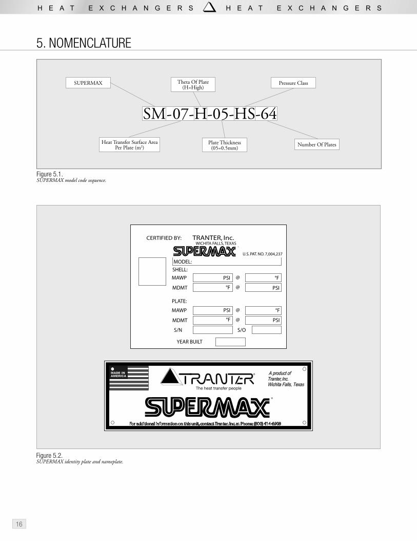
5. NOMENCLATURE
SUPERMAX
Heat Transfer Surface Area Per Plate (m2)
Theta Of Plate(H=High)
Plate Thickness(05=0.5mm)
Pressure Class
Number Of Plates
SM-07-H-05-HS-64
Figure 5.1.SUPERMAX model code sequence.
Figure 5.2.SUPERMAX identity plate and nameplate.
���������������������������������������������������������������������������������������
�
������
�����
����������
��� ���
������
������
����
�������������
�������������
�
�
�
�����������������������
���������������������������������
�������������
�
���
���
���
���
��
��
��
��

17
6. ADDITIONAL INFORMATION
6.1. Ordering PartsWhen ordering parts or requesting information, always give the Model and Serial Number of the unit.
6.2. Damaged ShipmentsOur equipment is carefully packaged and shipped in good condition. Shipments are made at the consignee’s risk. Upon receipt of shipments, carefully inspect the packaging and equipment for damage. In the event of loss or damage all claims should be made to the carrier. A copy of this claim should be sent to the factory location shown on the name plate. Factory addresses are provided in Section 6.4.
6.3. ReturnsUnits or parts are not to be returned without first obtaining permission from your nearest Tranter, Inc., plant. Parts authorized for return must be properly packaged and labeled and in good condition upon arrival at the Tranter, Inc., plant. All credits for returned materials will be subject to restocking and transportation charges.
6.4. Information And SupportThis manual is also available on-line at www.tranter.com. For any additional information concerning the operation, care or maintenance of your SUPERMAX, feel free to contact our SUPERMAX technical specialists at one of our manufacturing locations. Visit our web site for parts quotations at www.tranter.com, or e-mail us directly at any of our support locations or at [email protected].
Tranter, Inc.1900 Old Burk HighwayWichita Falls, TX 76306Tel. 1-800-414-6908 • Fax: 940-723-5131
Tranter International ABWakefield FactoryTranter Ltd, Unit 50Monckton Road Industrial EstateWakefield WF2 7AL EnglandTel. +44-1924 298 393 • Fax: +44-1924 219 596
Tranter International ABRegementsgatan 32PO Box 1325SE-462 28 Vänersborg SwedenTel. +46 521 799 800 • Fax: +46 521 799 822
Tranter India Pvt. Ltd.Gat. No. 985, Sanaswadi Tal. ShirurDist.Pune -412 208 (India)Tel. +91-2137 392 300 • Fax: +91 2137 252 612
6.5. Authorized Service CentersTo obtain additional information on operation and maintenance, contact your local Tranter, Inc., representative or the nearest Tranter, Inc., factory-authorized Service Center.
Tranter, Inc.Factory/Sales/Engineering Office1900 Old Burk HighwayWichita Falls, TX 76306Tel. 1-800-414-6908 • Fax: 940-723-5131E-mail: [email protected]
Tranter Service Center1213 Conrad SauerHouston, TX 77043Tel. 1-800-414-6908 • Fax: 713-467-1502E-mail: [email protected]
Tranter Midwest Service Center30241 Frontage RoadFarmersville, IL 62533Tel. 217-227-3470E-mail: [email protected]
Tranter International ABWakefield FactoryTranter Ltd, Unit 50Monckton Road Industrial EstateWakefield WF2 7AL EnglandTel. +44-1924 298 393 • Fax: +44-1924 219 596E-mail: [email protected]
Tranter International ABRegementsgatan 32PO Box 1325SE-462 28 Vänersborg SwedenTel. +46 521 799 800 • Fax: +46 521 799 822E-mail: [email protected]
Tranter International ABKäthe-Paulus-Strasse 9Postfach 10 12 14DE-31137 Hildesheim GermanyTel. +49-512 175 2077 • Fax: +49-512 188 8561E-mail: [email protected]
Tranter International ABVia Ercolano, 24IT-20052 Monza MI ItalyTel: +39-039 28 282 210 • Fax: +39-039 834 315E-mail: [email protected]
Tranter Ind e Com de Equipamentos LtdaAv. Leonil Cre Bortolosso, 88 Galpão 1 -Vila Quitaúna06194-971 Osasco, SP BrazilTel. +55 11 3608-4154E-mail: [email protected]
Tranter India Pvt. Ltd.Gat. No. 985, Sanaswadi Tal. ShirurDist.Pune -412 208 (India)Tel. +91-2137 392 300 • Fax: +91 2137 252 612E-mail: [email protected]

18
NOTES

19

www.tranter.com
SM-IOM-1-0207 650569 © 2007 Tranter, Inc.
The SUPERMAX® Shell and Plate Heat Exchanger is covered under US Pat. No. 7,004,237.
At the forefront of heat exchanger technology for more than 70 years
Tranter top quality, high-performance, proprietary products are on the job in demanding industrial and commercial installations around the world. Backed by our comprehensive experience and worldwide presence, Tranter offers you exceptional system performance, ap-plications assistance and local service. Tranter is close to its customers, with subsidiary companies, agents, distributors and representatives located worldwide. Contact us for a qualified discussion of your needs.
North/South America
Tranter, Inc.Wichita Falls, TX USATel: (940) 723-7125Fax: (940) 723-5131E-mail: [email protected]
Europe
Tranter International ABStockholm, SwedenTel: +46 (0)8 442 49 70Fax: +46 (0)8 442 49 80 E-mail: [email protected]
Middle East/Asia/Africa
Tranter India Pvt. LtdPune, IndiaTel: +91 20-30519300Fax: +91 20-30519350 E-mail: [email protected]