Installation and Operation Manual - Softener Parts and Operation Manual 2 CENTRAL WATER FILTRATION...
23
How to install, operate and maintain your Central Water Filtration System Model WHELJ1 Whirlpool Gold ® Central Water Filtration System System tested and certified by NSF International against NSF/ANSI Standard 42. See performance data sheet for details. System tested and certified by the Water Quality Association against CSA B483.1. 7302940 (Rev R 5/27/11) Product No. W10114885B Manufactured and warranted by Ecodyne Water Systems 1890 Woodlane Drive Woodbury, MN 55125 If you have any questions or concerns when installing, operating or maintaining your Central Water Filtration System, call our toll free number: 1-866-986-3223 Monday - Friday, 8 AM - 7 PM EST or visit www.ecodynewatertreatment.com When you call, please be prepared to provide the model, date code and serial number of your product, located on the rating decal on back of the cover. Printed on recycled paper Installation and Operation Manual
Transcript of Installation and Operation Manual - Softener Parts and Operation Manual 2 CENTRAL WATER FILTRATION...

How to install, operateand maintain your CentralWater Filtration System
Model WHELJ1Whirlpool Gold®Central WaterFiltration System
System tested and certified by NSF Internationalagainst NSF/ANSI Standard 42.
See performance data sheet for details.
System tested and certified by the Water QualityAssociation against CSA B483.1.
7302940 (Rev R 5/27/11)Product No. W10114885B
Manufactured and warranted byEcodyne Water Systems1890 Woodlane DriveWoodbury, MN 55125
If you have any questions or concerns wheninstalling, operating or maintaining your CentralWater Filtration System, call our toll free number:
1-866-986-3223Monday - Friday, 8 AM - 7 PM EST or visitwww.ecodynewatertreatment.com
When you call, please be prepared to provide themodel, date code and serial number of your product,located on the rating decal on back of the cover.
Printed on recycled paper
Installation
and O
peratio
n Manual

2
CENTRAL WATER FILTRATION SYSTEM WARRANTYWarrantor: Ecodyne Water Systems, 1890 Woodlane Drive, Woodbury, MN 55125
Warrantor guarantees, to the original owner, that:One Year Full Warranty:
For a period of one (1) year after installation, all parts will be free from defects in materials and workmanship and willperform their normal functions.For a period of one (1) year after installation, labor to repair or replace any part deemed to be defective in materials orworkmanship, will be provided at no additional cost.
Limited Warranties:Limited ten (10) year warranty, from date of purchase, the fiberglass filtration media tank will not rust, corrode, leak,burst, or in any other manner, fail to perform its proper functions; and thatLimited three (3) year warranty, after installation, electronic control board will be free of defects in materials and work-manship and will perform its normal functions.
If, during such respective period, a part proves to be defective, Warrantor will ship a replacement part, directly to yourhome, without charge. After the first year, labor necessary to maintain this product is not covered by the product warranty.If you have questions regarding a warranted product, need assistance with installation or troubleshooting, wish to order apart or report a warranty issue, we are just a phone call away. SIMPLY DIAL 1-866-986-3223, Monday - Friday, 8 am - 7pm EST, for assistance.
General ProvisionsThe above warranties are effective provided the Central Water Filtration System is operated at water pressures not ex -ceed ing 125 psi, and at water temperatures not exceeding 120°F; provided further that the Central Water Filtration Systemis not subject to abuse, misuse, alteration, neglect, freezing, accident or negligence; and provided further that the CentralWater Filtration System is not damaged as the result of any unusual force of nature such as, but not limited to, flood, hurri-cane, tornado or earthquake.Warrantor is excused if failure to perform its warranty obligations is the result of strikes, government regulation, materialsshortages, or other circumstances beyond its control.*THERE ARE NO WARRANTIES ON THE CENTRAL WATER FILTRATION SYSTEM BEYOND THOSE SPECIFICALLYDESCRIBED ABOVE. ALL IMPLIED WARRANTIES, INCLUDING ANY IMPLIED WARRANTY OF MERCHANTABILITYOR OF FITNESS FOR A PARTICULAR PURPOSE, ARE DISCLAIMED TO THE EXTENT THEY MIGHT EXTENDBEYOND THE ABOVE PERIODS. THE SOLE OBLIGATION OF WARRANTOR UNDER THESE WARRANTIES IS TOREPLACE OR REPAIR THE COMPONENT OR PART WHICH PROVES TO BE DEFECTIVE WITHIN THE SPECIFIEDTIME PERIOD, AND WARRANTOR IS NOT LIABLE FOR CONSEQUENTIAL OR INCIDENTAL DAMAGES. NO WAR-RANTOR DEALER, AGENT, REPRESENTATIVE, OR OTHER PERSON IS AUTHORIZED TO EXTEND OR EXPANDTHE WARRANTIES EXPRESSLY DESCRIBED ABOVE.Some states do not allow limitations on how long an implied warranty lasts or exclusions or limitations of incidental or con-sequential damage, so the limitations and exclusions in this warranty may not apply to you. This warranty gives you spe-cific legal rights, and you may have other rights which vary from state to state. This warranty applies to consumer-ownedinstallations only.
® Registered trademark/TM Trademark of Whirlpool, USA.Manufactured under license by Ecodyne Water Systems, Woodbury, Minnesota.
© 2009 Whirlpool Corporation. All rights reserved.
TABLE OF CONTENTSPage
Specifications & Dimensions . . . . . . . . . . . . . . . . . . . . . . . . . . . . . . . . . . . . . . . . . . . . . . . . . . . . . . . . . . . . . . . . . . . 3Central Water Filtration System Safety . . . . . . . . . . . . . . . . . . . . . . . . . . . . . . . . . . . . . . . . . . . . . . . . . . . . . . . . . . . 4Before You Start . . . . . . . . . . . . . . . . . . . . . . . . . . . . . . . . . . . . . . . . . . . . . . . . . . . . . . . . . . . . . . . . . . . . . . . . . . . . 4Inspect Shipment . . . . . . . . . . . . . . . . . . . . . . . . . . . . . . . . . . . . . . . . . . . . . . . . . . . . . . . . . . . . . . . . . . . . . . . . . . . . 5How a Central Water Filtration System Works . . . . . . . . . . . . . . . . . . . . . . . . . . . . . . . . . . . . . . . . . . . . . . . . . . . . . 5Installation Requirements . . . . . . . . . . . . . . . . . . . . . . . . . . . . . . . . . . . . . . . . . . . . . . . . . . . . . . . . . . . . . . . . . . . . 6-8Installation Instructions . . . . . . . . . . . . . . . . . . . . . . . . . . . . . . . . . . . . . . . . . . . . . . . . . . . . . . . . . . . . . . . . . . . . . 9-11Programming the Central Water Filtration System . . . . . . . . . . . . . . . . . . . . . . . . . . . . . . . . . . . . . . . . . . . . . . . . . 12Start Up Procedure . . . . . . . . . . . . . . . . . . . . . . . . . . . . . . . . . . . . . . . . . . . . . . . . . . . . . . . . . . . . . . . . . . . . . . . . . 13Customizing Features / Options . . . . . . . . . . . . . . . . . . . . . . . . . . . . . . . . . . . . . . . . . . . . . . . . . . . . . . . . . . . . . 14-15Care of Your Central Water Filtration System . . . . . . . . . . . . . . . . . . . . . . . . . . . . . . . . . . . . . . . . . . . . . . . . . . . . . 16Troubleshooting . . . . . . . . . . . . . . . . . . . . . . . . . . . . . . . . . . . . . . . . . . . . . . . . . . . . . . . . . . . . . . . . . . . . . . . . . 17-19Exploded View & Parts List . . . . . . . . . . . . . . . . . . . . . . . . . . . . . . . . . . . . . . . . . . . . . . . . . . . . . . . . . . . . . . . . 20-23

3
Model WHELJ1Rated Service Flow Rate 6.0 gpmPressure Drop at Rated Service Flow 10 psig*Pressure Drop at 9.6 gpm 15 psig*Water Pressure Limits (minimum / maximum) 30 - 125 psiWater Temperature Limits (minimum / maximum) 40 - 120 °FDrain Flow Rate 3.4 gpm
0.50 ppm0.75 ppm
Rated Capacity at Chlorine Concentration** of: 1.0 ppm1.5 ppm2.0 ppm
2,280,000 gal.*1,520,000 gal.*1,140,000 gal.*760,000 gal.*570,000 gal.*
Sediment Removal with 30-40 micron particle size 95% or moreSediment Removal with 40-50 micron particle size 99% or more* From independent laboratory test data.** Typical residential chlorine concentration is 0.5 to 1.0 ppm.
Specifications & Dimensions
Questions? Call Toll Free 1-866-986-3223 Monday- Friday, 8 AM - 7 PM ESTor visit www.ecodynewatertreatment.com
When you call, please be prepared to provide the model, date code and serial number,located on the rating decal on back of the cover.
FIG. 1
27-1/2”33-3/4”
3-3/8” 13-7/16”
10-1/8”
IN – OUT
OUT
IN
TOP VIEW
SIDE VIEW FRONT VIEW

4
Before You Start= Do not turn the Central Water Filtration System upside down, drop, or set on sharp protrusions.= The Central Water Filtration System has a maximum allowable inlet water pressure of 125 psi and a minimum of30 psi. If daytime pressure is over 80 psi, nighttime pressure may exceed the maximum. Use a pressure reduc-ing valve if necessary (Adding a pressure reducing valve may reduce the flow.). If your home is equipped with aback flow preventer, an expansion tank must be installed in accordance with local codes and laws.
= The Central Water Filtration System works on 24 volt, 60 Hz electrical power only, supplied by a direct plug-intransformer (included). Be sure to use the included transformer and plug it into a nominal 120V, 60 cycle house-hold outlet that is properly protected by an overcurrent device such as a circuit breaker or fuse. If transformer isreplaced, use only UL, CUL or CSA approved Class 2 transformer with the following specifications:
§ Input: 120 VAC, 60 Hz, 13.5 W § Output Voltage: 24 VAC § Output Current: 400 mA= Do not use the Central Water Filtration System with water that is microbiologically unsafe or of unknown qualitywithout adequate disinfection before or after the system.
European Directive 2002/96/EC requires all electrical and electronic equipment to be disposed of accord-ing to Waste Electrical and Electronic Equipment (WEEE) requirements. This directive or similar lawsare in place nationally and can vary from region to region. Please refer to your state and local laws forproper disposal of this equipment.
Central Water Filtration System SafetyYour safety and the safety of others are very important.
We have provided many safety messages in this manual and on your appliance. Always read and obey all safetymessages.
This is the safety alert symbol.This symbol alerts you to potential hazards that can kill or hurt you and others.All safety messages will follow the safety alert symbol and either the word “DANGER” or “WARNING”These words mean:
You can be killed or seriously injured if you don’timmediately follow instructions.You can be killed or seriously injured if you don’tfollow instructions.
All safety messages will tell you what the potential hazard is, tell you how to reduce the chance of injury, and tellyou what can happen if the instructions are not followed.
In the state of Massachusetts: The Commonwealth of Massachusetts plumbing code 248-CMR shallbe adhered to. A licensed plumber shall be used for this installation.
Do not return the Central Water Filtration System to store.If you have any questions, or there are missing parts or damage, please call Toll Free 1-866-986-3223,Monday - Friday, 8 am - 7 pm EST, or visit www.ecodynewatertreatment.comWhen you call, please be prepared to provide the model, date code and serial number, found on the ratingdecal on back of the cover.

How a Central Water Filtration System WorksNORMAL OPERATIONDuring normal operation water enters the CentralWater Filtration System and flows through several fil-tration processes where tastes, odors and sedimentare reduced.
CLEAN RINSE CYCLEA Clean Rinse cycle will automatically be initiatedbased on how the controller has been programmed.The Clean Rinse cycle lifts and expands the mediabed to rejuvenate the media and then repacks the bedfor continued use. During the Clean Rinse cycle, dirt,sediment, etc. are flushed from the Central WaterFiltration System down the drain.
APPLICATIONS FOR A CENTRAL WATERFILTRATION SYSTEM= Do not use the Central Water Filtration System withwater that is microbiologically unsafe or of unknownquality without adequate disinfection before or afterthe system.
= The Central Water Filtration System may not be aneffective treatment method for water sources with ahydrogen sulfide problem (rotten egg odor or taste)If your water has hydrogen sulfide, contact a watertreatment expert or call 1-866-986-3223.
= The Central Water Filtration System will not removeiron and is not intended to replace iron treatmentequipment.
= Although the Central Water Filtration System hassediment filter capabilities, additional sediment filtra-tion may be needed in problem water applications.
5
Packing List
Inspect Shipment
Ground ClampKit 10 ft. Drain HoseBypass Valve
Adaptor Elbow
InstallationAdaptors
FIG. 2Hose Clamps
The parts required to assemble and install the CentralWater Filtration System are included with the unit.Thoroughly check the Central Water Filtration Systemfor possible shipping damage and parts loss. Alsoinspect and note any damage to the shipping carton.
Remove and discard (or recycle) all packing materials.To avoid loss of small parts, we suggest you keep thesmall parts in the parts bag until you are ready to usethem.
Clips

6
LOCATION REQUIREMENTSConsider the following when selecting an installationlocation for the Central Water Filtration System.= Do not operate the Central Water Filtration Systemwhere freezing temperatures occur. Do not attemptto treat water over 120ºF. Freezing temperatures orhot water damage voids the warranty.
= To condition all water in the home, install theCentral Water Filtration System close to the watersupply inlet, and before all other plumbing connec-tions, except outside water pipes.
= Install the Central Water Filtration System betweenthe home’s incoming water supply and the watersoftener, if one is being used (See Figure 3).
= A nearby drain is needed to carry away CleanRinse discharge water. Use a floor drain, laundrytub, sump, standpipe, or other options (check yourlocal codes). See "Air Gap Requirements" and"Valve Drain Requirements" sections. If a drain isnot available, it is still possible to operate theCentral Water Filtration System in a manual CleanRinse mode. See “Operating in Manual CleanRinse Mode.” The automatic Clean Rinse must bedisabled if the Central Water Filtration System willnot be connected to a drain (See Page 7).
Installation Requirements
THE PROPER ORDER TO INSTALL WATER TREATMENT EQUIPMENT
FIG. 3
PressureTank
City Water Supply
Well Water Supply
WellPump
OR
CentralWaterFiltrationSystem
OptionalSedimentFilter
WaterHeater
WaterSoftener
Untreated Water toOutside Faucets
Hot Waterto House
Cold Waterto House
= The Central Water Filtration System works on24 volt, 60 Hz electrical power only, supplied by adirect plug-in transformer (included). Provide anelectrical outlet in accordance with NEC and localcodes.
= Do not install the Central Water Filtration System ona hot water line (See Figure 3, below).
= Avoid installing in direct sunlight. Excessive sunheat may cause distortion or other damage to non-metallic parts.

7
Installation RequirementsPLUMBING CODESAll plumbing must be completed in accordance withnational, state and local plumbing codes.
VALVE DRAIN REQUIREMENTSUsing the flexible drain hose (included), measure andcut to the length needed. Flexible drain hose is notallowed in all localities (check your plumbing codes). Iflocal codes do not allow use of a flexible drain hose, arigid valve drain run must be used. Purchase a com-pression fitting (1/4 NPT x 1/2 in. minimum tube) and1/2" tubing from your local hardware store. Plumb arigid drain as needed (see Figure 4, below).NOTE: Avoid drain hose runs longer than 30 feet.
Make the valve drain line as short and directas possible.
It is recommended that the Central Water FiltrationSystem be installed near a drain. However, if a drainis not available, it is still possible to operate theCentral Water Filtration System in a manual CleanRinse mode. See “Operating in Manual Clean RinseMode” section. The automatic Clean Rinse functionmust be disabled if the Central Water Filtration Systemwill not be connected to a drain.
1-1/2”air gap
Install adaptorelbow using hoseclamp. Aim noz-zle down towardcenter of drain
Tie or wiretubing inplace
FIG. 4
LAUNDRY TUB STANDPIPE
1-1/2”air gap
FLOOR DRAIN
1-1/2”air gap
To drain point otherthan floor drain.Support tubing inplace as needed.
DrainFitting
Clip
Barbs1/4 NPT Threads
1/2” Outside Dia.Copper Tube(not included)
Comp Fitting. 1/4NPT x 1/2” O.D.
Tube (not included)
Cut barbs fromdrain fitting (pullclip to remove fit-ting from valve)
CONNECTING VALVE TO DRAINSUBSTITUTING RIGID DRAIN LINE
HoseClamp
ValveDrainHose
Drain grate with 1”dia. hole in center
In the state of Massachusetts: The Commonwealthof Massachusetts plumbing code 248-CMR shallbe adhered to. A licensed plumber shall be usedfor this installation.
AIR GAP REQUIREMENTSA drain is needed for Clean Rinse discharge water. Afloor drain, close to the Central Water FiltrationSystem, is preferred. A laundry tub, standpipe, etc.are other drain options. Secure valve drain hose inplace. Leave an air gap of 1-1/2” between the end ofthe hose and the drain. This gap is needed to preventbackflow of sewer water into the Central WaterFiltration System . Do not put the end of the drainhose into the drain.

8
Installation RequirementsINLET - OUTLET PLUMBING OPTIONSAlways install either a single bypass valve (provided)to the contractor/plumber-supplied plumbing, as shownin Figure 7 OR if desired, a 3 valve bypass system(parts not included) can be installed, as shown inFigure 6. Bypass valves allow you to turn off water tothe Central Water Filtration System for maintenance ifneeded, but still have water in house pipes.
Use either:= Copper pipe= Threaded pipe= PEX (Crosslinked Polyethylene) pipe= CPVC plastic pipe= Other pipe approved for use with potable water
IMPORTANT: Do not solder with plumbing attached toinstallation adapters and single valvebypass. Soldering heat will damage theadapters and valve.
FIG. 7
FIG. 6
3 VALVE BYPASS
Central Water FiltrationSystem INLET
CONNECTING PLUMBING TO VALVE
2 of eachincluded
1” NPTAdapterClip
1” NPT SweatAdapter (2)(not included)
Use teflon tape,pipe joint com-pound or both
BypassValveValve
Inlet
INOUT
INOUTUse teflon tape,pipe joint com-pound or both
Clip
ValveInlet
1” NPTAdapter
2 of eachincluded
1” NPT SweatAdapter (2)(not included)
CROSS OVER
FIG. 5To Central WaterFiltration System
Main Water Pipe
In what direction does the water flow?Be sure to plan piping so water flow is to theCentral Water Filtration System valve INLET.Plan a crossover if flow is from left to right.
TreatedWater from
ValveOUTLET
Central Water FiltrationSystem OUTLET
UntreatedWater toValveINLET

9
Installation InstructionsTURN OFF WATER SUPPLY1. Close the main water supply valve, near the wellpump or water meter.
2. Open all faucets to drain water from the housepipes.
NOTE: Be sure not to drain water from the waterheater, as damage to the water heater ele-ments could result.
MOVE THE CENTRAL WATER FILTRATIONSYSTEM INTO PLACE
Post
Top Cover
REMOVE TOP COVER AND HANG ITFROM POST ON FRONT OF RIM
FIG. 9
PlywoodShim(s)
LEVEL IF NECESSARY
FIG. 81. Move the Central Water Filtration System into instal-lation position. Set it on a level surface. If needed,place the unit on a section of plywood, a minimumof 5/8” thick. Then place shims under the plywoodto level the Central Water Filtration System (seeFigure 8).
2. Remove top cover.3. Hang cover from post on front of rim, as shown inFigure 9. Avoid allowing cover to hang from wires.
Excessive Weight HazardUse two or more people to move and installCentral Water Filtration System.Failure to do so can result in back or otherinjury.

10
1. Install metal grounding clamp to metal house watersupply pipes before beginning installation.
2. Securely tighten connection in center of metalground clamp (See Figure 10).
3. Loosely assemble any pipe and fittings needed fromthe main water supply to the inlet and outlet ports ofthe Central Water Filtration System valve.
IMPORTANT:= Be sure to fit, align and support all plumbing to pre-vent putting stress on the Central Water FiltrationSystem valve inlet and outlet. Undue stress frommisaligned or unsupported plumbing may causedamage to the valve.
= Be sure to keep fittings fully together, and pipessquared and straight.
= Be sure incoming water supply pipe goes to theCentral Water Filtration System valve INLET side.Inlet and outlet are marked on the valve. Trace thewater flow direction to be sure.
4. Complete the inlet and outlet plumbing for the typeof pipe as described at right:
Installation Instructions
FIG. 10
GroundClamp (2)
Screw withlock washer
& nutPlasticBypassValve
MetalPipes
Soldered Copper1. Thoroughly clean and apply solder flux to all joints.2. Make all solder connections.IMPORTANT: Do not solder with plumbing attached to
installation Adapters and single valvebypass. Soldering heat will damage theAdapters and valve.
Threaded Pipe1. Apply pipe joint compound or Teflon® tape to allmale pipe threads.
2. Tighten all threaded joints and make all solder con-nections.
CPVC Plastic Pipe1. Clean, prime and cement all joints, following themanufacturer's instructions supplied with the plasticpipe and fittings.
Other, including PEX (CrosslinkedPolyethylene)1. Follow the piping system manufacturer's instructionswhen using other pipe approved for potable water.
® Teflon is a registered trademark of E.I. Du Pont deNemours and Company.
Electrical Shock HazardInstall metal ground clamp to metal housewater supply pipe before beginning installation.Securely tighten connection in center of metalground clamp.Failure to do so can result in death orelectrical shock.
ASSEMBLE INLET AND OUTLET PLUMBINGA ground clamp should be installed on the householdplumbing supply lines in accordance with the NationalElectric Code.

11
Installation Instructions
FIG. 11
SINGLE BYPASS VALVE
Pull handleOUT for normaloperation
Push handle INfor BYPASS
INSTALL VALVE DRAIN HOSE1. Measure, cut to needed length and connect the 3/8"drain line (provided) to the Central Water FiltrationSystem valve drain fitting (See Figure 11). Use ahose clamp to hold the hose in place.
NOTE: If codes require a rigid drain line see “ValveDrain requirements" section.
2. Run the drain hose or copper tubing to the floor drain.Secure drain hose. This will prevent the drain linefrom “whipping'' during Clean Rinse cycles. See “AirGap Requirements" section.
TEST FOR LEAKS1. Make sure the single bypass valve (or 3 valve bypass,if installed) is in the bypass position, with the handlepushed in (See Figure 11).
2. Fully open the main water supply valve.3. Briefly open a faucet in the house to refill the plumb-ing with water.
4. Slowly move the bypass valve(s) to the normal opera-tion position, pausing several times to allow the unit topressurize slowly (See Figure 11).
5. Check for leaks at all the plumbing connections youmade.
IMPORTANT: Start up procedure must be run prior tousing any filtered water. Follow theinstructions below and on Page 13.
TURN ON THE CENTRAL WATER FILTRA-TION SYSTEMDuring installation, the Central Water Filtration Systemwiring may be moved or jostled from place. Check to besure all leadwire connectors are secure on the back ofthe electronic board and be sure all wiring is away fromthe valve gear and motor area, which rotates duringClean Rinse cycles.1. Plug the Central Water Filtration System’s transformerinto an electrical outlet that is not controlled by aswitch.
2. In the display, the words “PRESENT TIME” appearand 12:00 PM begins to flash. Set the clock accord-ing to the “Set Time of Day” section on Page 12.
3. Run the start up procedure, as detailed on Page 13.
Drain LineConnection

12
Programming the Central Water Filtration System
When the transformer is plugged into the electricaloutlet, a model code and a test number (example:J2.0), begin to flash in the faceplate display. Then,12:00 PM and the words “PRESENT TIME" begin toflash.NOTE: If “- - - -” shows in the display, press the r
UP or s DOWN button until the model code“CF 8” shows in the display. Then, press thePROGRAM button to set, and change to theflashing “PRESENT TIME" display.
FIG. 12
UPbutton
DOWNbutton
Display
CLEANbutton
PROGRAMbutton
NOTE: Press buttons and quickly release to slowlyadvance the display. Hold the buttons downfor fast advance.
2. Press the PROGRAM button a few times, until thetime appears on the display, but is not flashing.
FIG. 13
SET TIME OF DAYIf the words “PRESENT TIME" do not show in the dis-play, press the PROGRAM button until they do.1. Press the r UP or s DOWN buttons to set thepresent time. Up moves the display ahead; downsets the time back. Be sure AM or PM is correct.
Questions? Call Toll Free 1-866-986-3223 Monday- Friday, 8 AM - 7 PM ESTor visit www.ecodynewatertreatment.com
When you call, please be prepared to provide the model, date code and serial number,located on the rating decal on back of the cover.

13
Start Up ProcedureIMPORTANT:Run the start up cycle immediately aftercompleting installation, before using anywater in the home.The filtration media in this Central Water FiltrationSystem contains a small number of harmless activatedcarbon particles generated during shipping that aresmall enough to exit the system with water flow. It isnormal for these particles to cause a temporary discol-oration of the water coming out of the system. Toavoid discolored water at your home’s faucets the sys-tem’s start up cycle should be initiated to rinse the par-ticles and any discolored water down the drain.If the Central Water Filtration System is used withoutfirst running the start up cycle, you will notice that thewater will temporarily have a gray color until the parti-cles have exited the system.To Initiate the start up cycle:1. Make sure the drain hose is attached to the CentralWater Filtration System and the other end issecured over a drain (see “Install Valve Drain Hose”on Page 11).
2. Make sure bypass valve is in the “service” (open orfiltered water) position and the home’s water supplyis turned on.
3. Press and hold the CLEAN button to initiate thestart up cycle. The button can be released whenyou hear the valve changing position and“RECHARGE NOW” flashes in the display.
During the start up cycle:Throughout the start up cycle you will hear the valvechanging position and notice the flow of water to drainstarting and stopping. The start up cycle will takeapproximately 20 minutes. Avoid using water duringthis time. Do not set the time of day or press otherbuttons during the start up cycle, as this will interruptthe start up cycle. Do not unplug the transformer dur-ing the start up cycle. If the start up cycle is interrupt-ed, it should be initiated again and allowed to run tocompletion.After the start up cycle:Once the start up procedure completes successfully, itcannot be initiated a second time. The Central WaterFiltration System will automatically return to the normaloperation position. Once the start up cycle has run, afaucet in the home should be opened and waterallowed to run for 10 minutes at the system’s ratedflow. If, after running the start up cycle, the water stillappears discolored, manually run Clean Rinse cycles(See Page 14) until the water is clear.If the time of day was not set before the start up cycle,set it now (See Page 12).Check the new plumbing connections and joints oncemore for leaks.
Questions? Call Toll Free 1-866-986-3223 Monday- Friday, 8 AM - 7 PM ESTor visit www.ecodynewatertreatment.com
When you call, please be prepared to provide the model, date code and serial number,located on the rating decal on back of the cover.

14
Customizing Features / Options
SET NUMBER OF DAYS BETWEENCLEAN RINSE CYCLESBy default the Central Water Filtration System willautomatically initiate a Clean Rinse every 14 days.This should be sufficient for most applications.To change the number of days between Clean Rinsecycles:1. Press the PROGRAM button until “RECHARGE” isshown in the display.
2. Press the r UP or s DOWN buttons to set thenumber of days between Clean Rinse cycles (from 1to 99).3. Press the PROGRAM button again when com-plete.
SET CLEAN RINSE TIMEBy default the Central Water Filtration System willClean Rinse at 1:00 a.m.To change the Clean Rinse start time:1. Press the PROGRAM button until “RECHARGETIME” is shown in the display.
FIG. 15
2. Press the r UP or s DOWN buttons to set theClean Rinse time. Be sure AM or PM is correct.3. Press the PROGRAM button again when com-plete.
FIG. 16
SET LENGTH OF CLEAN RINSEBy default the Central Water Filtration System’sClean Rinse cycle will consist of a 2 minute back-wash followed by a 1 minute fast rinse. This shouldbe sufficient for most applications.Increasing the length of Clean Rinse time willincrease the amount of water flushed to drain duringeach Clean Rinse cycle, therefore, these timesshould only be increased when necessary.To change the length of the backwash part of theClean Rinse cycle:1. Press and hold the PROGRAM button for a fewseconds, until the “000--” screen appears, as shownin Figure 17.
2. Press the PROGRAM button once, so “bA TIME”appears in the display.
FIG. 17
3. Press the r UP or s DOWN buttons to set thelength of backwash in minutes.4. Press the PROGRAM button again when com-plete.To change the length of the fast rinse part of theClean Rinse cycle:1. Press and hold the PROGRAM button for a fewseconds, until the “000--” screen appears, as shownin Figure 17.2. Press the PROGRAM button once, so “Fr TIME”appears in the display.
3. Press the r UP or s DOWN buttons to set thelength of fast rinse in minutes.4. Press the PROGRAM button again when com-plete.
FIG. 18
FIG. 19
FIG. 14
START A CLEAN RINSE CYCLETo manually start a Clean Rinse cycle, press andhold the CLEAN button for a few seconds, until“RECHARGE NOW” flashes in the display.
15
Customizing Features / OptionsOPERATING IN MANUAL CLEAN RINSEMODEClean Rinse cycles will run automatically, unless theautomatic Clean Rinse function has been disabled. Ifthis function has been disabled, it will be necessary tomanually initiate any Clean Rinse cycles. It is recom-mended that a Clean Rinse cycle should be run atleast once each month, or more frequently if neces-sary.A manual Clean Rinse mode may be used when adrain (required for automatic Clean Rinse) is notavailable. However, it is recommended that automat-ic Clean Rinse be used if the drain requirements canbe met.IMPORTANT: During the Clean Rinse cycle, whethermanually or automatically initiated, water will flowfrom the valve drain port. If a permanent drain linehas not been installed, provisions must be made forthe drain flow prior to initiating a Clean Rinse cycle.DISABLING AUTOMATIC CLEAN RINSETo disable the automatic Clean Rinse function:1. Press and immediately release the CLEAN button(pressing and holding the button a few seconds wouldinitiate a Clean Rinse cycle).2. “VAC” should flash in the display, as shown inFigure 20, indicating that the Central Water FiltrationSystem is in the manual Clean Rinse mode (the auto-matic Clean Rinse function has been disabled).
POWER OUTAGE MEMORYIf electrical power to the Central Water FiltrationSystem is lost, “memory'' built into the controller cir-cuitry will keep all settings for up to eight hours.While the power is out, the display is blank and theCentral Water Filtration System will not Clean Rinse.When electrical power is restored, you have to resetthe time of day only if the display is flashing. TheClean Rinse TIME never requires resetting unless achange is desired. Even if the clock is incorrect aftera long power outage, the Central Water FiltrationSystem works as it should to keep your water treated.However, Clean Rinse cycles may occur at the wrongtime of day until you reset the clock to the correcttime of day.NOTE: If the Central Water Filtration System was in a
Clean Rinse cycle when power was lost, it willnow finish the cycle.
MANUALLY STARTING A CLEAN RINSE CYCLETo manually start a Clean Rinse cycle:1. Press and hold the CLEAN button for a few sec-onds, until “RECHARGE NOW” flashes in the display,as shown in Figure 21.
2. When the Clean Rinse cycle is complete, theCentral Water Filtration System will remain in themanual Clean Rinse mode.
FIG. 20
FIG. 21
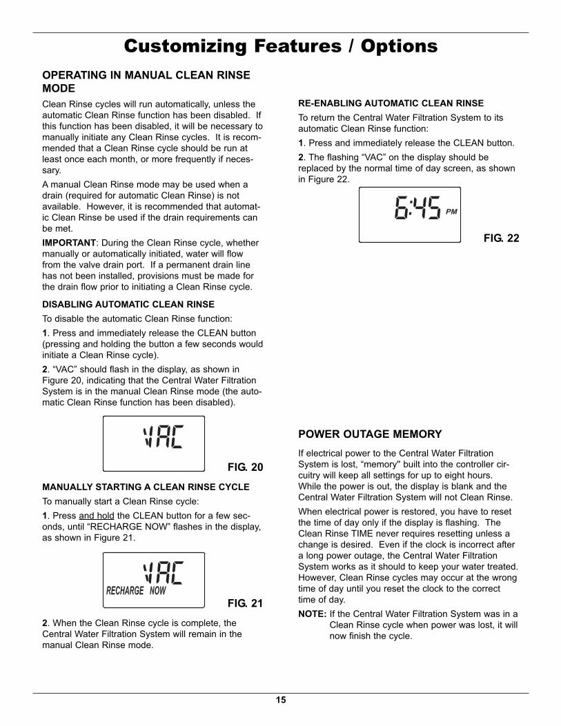
RE-ENABLING AUTOMATIC CLEAN RINSETo return the Central Water Filtration System to itsautomatic Clean Rinse function:1. Press and immediately release the CLEAN button.2. The flashing “VAC” on the display should bereplaced by the normal time of day screen, as shownin Figure 22.
FIG. 22

16
Care of Your Central Water Filtration SystemVACATIONS AND EXTENDED PERIODS OFNO WATER USEIf your Central Water Filtration System will not be usedfor an extended period of time (several months),please follow one of these recommendations:= If the water supply to the unit is not turned off, andthe automatic Clean Rinse function has not beendisabled, then no further actions are required.
= If the Clean Rinse cycle cannot be automaticallyrun, due to the water supply being shut off, thetransformer being unplugged or the automaticClean Rinse function being disabled, then it is rec-ommended that a minimum of 2 manually initiatedClean Rinse cycles be performed when the systemis placed back into operation (see Start a CleanRinse Cycle section on Page 14).
= In any installation where there is a possibility offreezing, the Central Water Filtration System shouldbe disconnected and the water drained (see Protectthe Central Water Filtration System from Freezingsection).
PROTECT THE CENTRAL WATER FILTRA-TION SYSTEM FROM FREEZINGIf the Central Water Filtration System is installed whereit could freeze (summer cabin, lake home, etc.), youmust drain all water from it to stop possible freezedamage. To drain the unit:1. Close the shut-off valve on the house main waterpipe, near the water meter or pressure tank.
2. Open a faucet in the filtered water pipes to ventpressure in the unit.
3. Move the stem in the single bypass valve to bypass.Close the inlet and outlet valve in a 3 valve bypasssystem, and open the bypass valve. If you wantwater in the house pipes again, reopen the shut-offvalve on the main water pipe.
4. Unplug the transformer at the wall outlet. Removethe cover. Take off the drain hose if it will interferewith moving the Central Water Filtration System intoposition over the drain.
5. Remove the large holding clips at the Central WaterFiltration System inlet and outlet. Separate the unitfrom the plastic installation adaptors, or from thebypass valve.
6. Lay a piece of 2 inch thick board near the floordrain.
DRAIN ALL WATER FROM CENTRALWATER FILTRATION SYSTEM
Floor DrainWood Block
FIG. 23
7. Move the Central Water Filtration System close tothe drain. Slowly and gently, tip it over until the rimrests on the wood block with the inlet and outletover the drain. Do not allow the unit’s weight to reston the inlet and outlet fittings or they may break.
8. Tip the bottom of the Central Water FiltrationSystem up a few inches and hold until all water hasdrained. Leave the unit laying like this until you areready to use it. Plug the inlet and outlet with cleanrags to keep dirt, bugs, etc. out.
Excessive Weight HazardUse two or more people to move and installCentral Water Filtration System.Failure to do so can result in back or otherinjury.

17
TroubleshootingPROBLEM CAUSE CORRECTION
Water has black orgray color
(NEW SYSTEM) Start up procedurehas not been completed
Run start up procedure (See Page 13) or runconsecutive Clean Rinse cycles (See Page 14)until water color returns to normal.
(NOT A NEW SYSTEM) Normal abra-sion of filtration media
Manually initiate a Clean Rinse cycle (See Page 14).
Low water pressure athouse faucets
Sediment filter screen is clogged Manually initiate a Clean Rinse cycle (See Page 14).Clean sediment filter screen (See Page 19). Ifthe filter screen is frequently plugging, it may benecessary to adjust the frequency of Clean Rinsecycles.
Filtration media pores are blocked Manually initiate a Clean Rinse cycle (See Page 14).If the filtration media pores are frequently block-ing, it may be necessary to increase the frequen-cy of Clean Rinse cycles.
Water has objection-able taste and/or odor
System is in bypass Move bypass valve(s) to normal operating (non-bypass) position.
Filtration media pores are blocked Manually initiate a Clean Rinse cycle (See Page 14).If the filtration media pores are frequently block-ing, it may be necessary to increase the frequen-cy of Clean Rinse cycles.
No water flow to drainduring Clean Rinsecycle
System is in bypass Move bypass valve(s) to normal operating (non-bypass) position.
Drain flow control is plugged Clean drain flow control (See Page 18).Drain hose is plugged or kinked Straighten drain hose.Transformer is unplugged from wallelectrical outlet (display will be blank)
Check for loss of power and correct.
Clean Rinse cycle doesnot run automatically
If display reads “VAC”, then CleanRinse function has been disabled
Press and release the CLEAN button until displayno longer reads “VAC”.
If display is blank, transformer may beunplugged from wall electrical outlet
Check for loss of power.
Clean Rinse cycle doesnot run at the pro-grammed time of day
If time display is flashing, then a longpower loss caused the clock to lose itstime setting
Reset the clock to the correct time of day (SeePage 12).
Steady beeping fromelectronic control
Electronic control board is wet Allow 48 hours for board to dry, or use blow dryer.
Error Code E1, E3 orE4 appears
Fault in wiring harness or connectionsto position switch
Replace wiring harness or connection to positionswitch (See parts list at end of this manual).
Fault in switch Replace switch (See parts list at end of this manual).
Fault in valve causing high torque Replace rotor/seal kit (instructions included with kit).Motor inoperative Replace motor (instructions included with motor)
Error Code E5 appears Electronic control Replace electronic control board (PWA) (instruc-tions included with PWA).
Need help troubleshooting? Call Toll Free 1-866-986-3223 Monday- Friday, 8 AM - 7 PM ESTor visit www.ecodynewatertreatment.com
When you call, please be prepared to provide the model, date code and serial number,located on the rating decal on back of the cover.

18
Troubleshooting
FIG. 24
REMOVING DRAIN FITTING TO CLEANFLOW CONTROL
Clip
HoseClamp
DrainHose
FlowControl Drain
Fitting
CLEANING THE DRAIN FLOW CONTROLThis procedure is not required if the Central WaterFiltration System is operating normally. It should beperformed only if a problem with lack of water flow todrain is encountered, as detailed in the troubleshootingtable on Page 17.1. Remove the clip holding the drain fitting into thevalve (See Figure 24).
2. Remove the drain fitting from the valve3. Clear any obstruction.4. Reinstall the drain fitting into the valve.5. Reinstall the clip to secure the drain fitting in thevalve.
PROBLEM CAUSE CORRECTIONWater running to thedrain (while unit is not inthe Clean Rinse cycle)
Inner valve defect causing leak Replace seals and rotor
Filter media in householdplumbing
Crack in distributor or riser tube Replace distributor or riser tube.
Procedure for removing error code from display:1. Unplug transformer from electrical outlet.2. Correct problem.3. Plug in transformer.4. Wait 6 minutes. The error code will return if the problem was not corrected.
Assistance from customer service may be needed with the following:
Need help troubleshooting? Call Toll Free 1-866-986-3223 Monday- Friday, 8 AM - 7 PM ESTor visit www.ecodynewatertreatment.com
When you call, please be prepared to provide the model, date code and serial number,located on the rating decal on back of the cover.
19
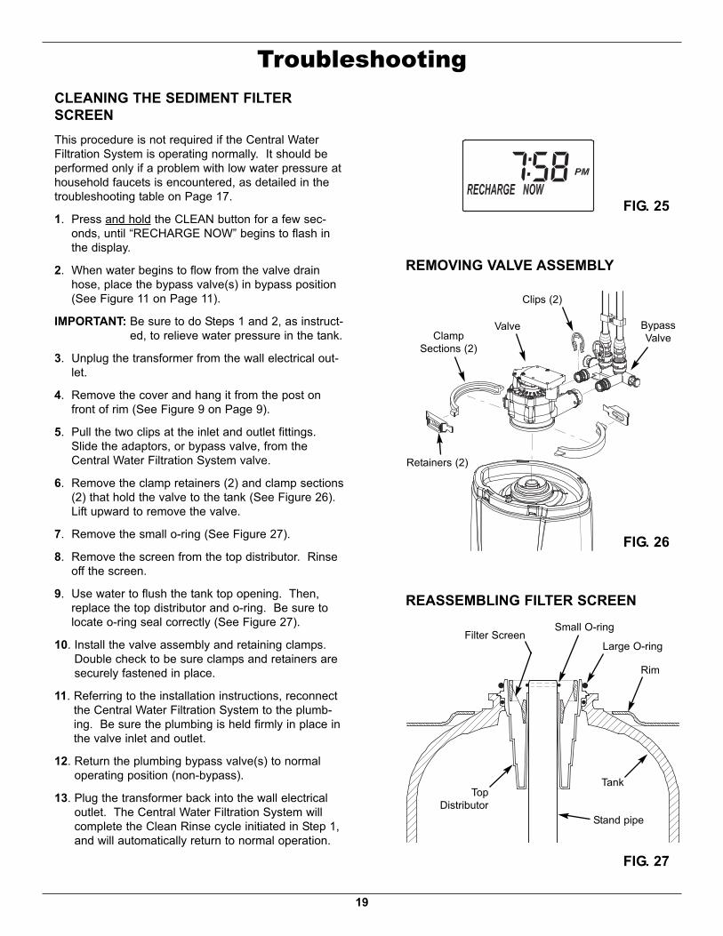
TroubleshootingCLEANING THE SEDIMENT FILTERSCREENThis procedure is not required if the Central WaterFiltration System is operating normally. It should beperformed only if a problem with low water pressure athousehold faucets is encountered, as detailed in thetroubleshooting table on Page 17.1. Press and hold the CLEAN button for a few sec-onds, until “RECHARGE NOW” begins to flash inthe display.
2. When water begins to flow from the valve drainhose, place the bypass valve(s) in bypass position(See Figure 11 on Page 11).
IMPORTANT: Be sure to do Steps 1 and 2, as instruct-ed, to relieve water pressure in the tank.
3. Unplug the transformer from the wall electrical out-let.
4. Remove the cover and hang it from the post onfront of rim (See Figure 9 on Page 9).
5. Pull the two clips at the inlet and outlet fittings.Slide the adaptors, or bypass valve, from theCentral Water Filtration System valve.
6. Remove the clamp retainers (2) and clamp sections(2) that hold the valve to the tank (See Figure 26).Lift upward to remove the valve.
7. Remove the small o-ring (See Figure 27).8. Remove the screen from the top distributor. Rinseoff the screen.
9. Use water to flush the tank top opening. Then,replace the top distributor and o-ring. Be sure tolocate o-ring seal correctly (See Figure 27).
10. Install the valve assembly and retaining clamps.Double check to be sure clamps and retainers aresecurely fastened in place.
11. Referring to the installation instructions, reconnectthe Central Water Filtration System to the plumb-ing. Be sure the plumbing is held firmly in place inthe valve inlet and outlet.
12. Return the plumbing bypass valve(s) to normaloperating position (non-bypass).
13. Plug the transformer back into the wall electricaloutlet. The Central Water Filtration System willcomplete the Clean Rinse cycle initiated in Step 1,and will automatically return to normal operation.
FIG. 27
FIG. 26
REASSEMBLING FILTER SCREEN
RimLarge O-ring
Small O-ringFilter Screen
Stand pipe
TopDistributor
Tank
REMOVING VALVE ASSEMBLYClips (2)
ValveClampSections (2)
BypassValve
Retainers (2)
FIG. 25

20
Central Water Filtration System Exploded View
1
3
24
5
6
8
7
11
10
9
12
1319
16
17
18
22
2524
Valve AssemblySee Pages 22 & 23
for parts
23
20
21
14
15

21
Central Water Filtration System Parts List
To order repair parts call toll free 1-866-986-3223, Monday - Friday, 8 am - 7 pm EST.Manufactured and warranted by
Ecodyne Water Systems1890 Woodlane DriveWoodbury, MN 55125
Questions? Call Toll Free 1-866-986-3223 Monday- Friday, 8 AM - 7 PM ESTor visit www.ecodynewatertreatment.com
When you call, please be prepared to provide the model, date code and serial number,located on the rating decal on back of the cover.
Key No. Part No. Description¢ 7290876 Assembly, Replacement Mineral Tank, w/media & asso-
ciated components (Includes Key Nos. 1 through 12)1 7170296 O-Ring, 2-7/8” x 3-1/4”2 7170254 O-Ring, 13/16” x 1-1/16”3 7077870 Top Distributor4 7265025 Filter Screen5 7170270 O-Ring, 2-3/4” x 3”6 7105047 Repl. Bottom Distributor7 7088033 Retainer Clip (2 req.)8 7176292 Clamp Section (2 req.)9 Ù Mineral Tank, 8” x 25”10 Ù Activated Carbon, 10 lbs.11 Ù Filter Sand, 5 lbs.12 Ù Gravel, 6 lbs.13 7290402 Faceplate Decal14 7290119 Cover (order decal above and badge below)15 7290779 Whirlpool Brand Badge16 7290729 Repl. Electronic Control Board (PWA)17 7290101 Rim18 7296296 Outer Shroud Tank19 7275907 Transformer20 7259927 Wire Harness21 7139999 Drain Hose, 20 ft.22 1103200 Tube Adaptor (Elbow)23 7248706 Grounding Kit24 7278434 Bypass Valve25 7116713 Clip (2 req.)¢ 7302940 Owner’s Manual¢ Not illustrated.Ù Mineral Tank and media can only be purchased as part of the Replacement Mineral
Tank Assembly (See top of list).

22
Valve Assembly Exploded View
5150
53
54
55
56
57
60 59 58
52
6162
636465
66676869
70
71
72
73
7475
76
77
78
79
80
81
82
83
wear-stripseal
cross-sectionview

23
Valve Parts ListKey No. Part No. Description50 7224087 Screw, #8-32 x 1” (2 req.)51 7286039 Motor (incl. 2 ea. of Key No. 50)52 0900857 Screw, #6-20 x 3/8” (2 req.)53 7231385 Motor Plate54 0503288 Bearing55 7284964 Cam & Gear56 7142942 Clip, Drain57 0900431 Tubing Clamp (2 provided)58 7024160 Adapter, Drain Hose59 7170327 O-Ring, 5/8” x 13/16”60 7290410 Flow Plug61 7170238 O-Ring, 7/16” x 5/8”62 7170212 O-Ring, 3/4” x 15/16”63 7082087 Wave Washer64 7199232 Rotor & Disc65 7170246 O-Ring, 3-3/8” x 3-5/8”66 7134224 Rotor Seal67 7170204 O-Ring, 3/8” x 9/16”68 7092642 Plug, Drain Seal69 7129889 Spring70 7116713 Clip (2 req.)71 7278442 Installation Adapter (2 req.)72 7170288 O-Ring (2 req.)73 7082053 Valve Body74 7081764 Seal, Nozzle & Venturi75 7170319 O-Ring, 1/4” x 3/8” (2 req.)76 7100940 Plug, Aspirator Port77 7081201 Retainer, Nozzle & Venturi78 7085263 Valve Cover79 7074123 Screw, #10-14 x 2 (5 req.)80 7077472 Expansion Pin81 7030713 Switch82 7325702 Spacer, Motor Mount83 7070412 Screw, #4-24 x 1-1/8”, Flat Head¢ 7129716 Seal Kit (incl. Key Nos. 59, 61, 62, 65, 66, 67 & 74)
To order repair parts call toll free 1-866-986-3223, Monday - Friday, 8 am - 7 pm EST.Manufactured and warranted by
Ecodyne Water Systems1890 Woodlane DriveWoodbury, MN 55125
Questions? Call Toll Free 1-866-986-3223 Monday- Friday, 8 AM - 7 PM ESTor visit www.ecodynewatertreatment.com
When you call, please be prepared to provide the model, date code and serial number,located on the rating decal on back of the cover.
¢ Not illustrated.