Installation and Operation Manual Pool/Spa Filters … Installation and Operation Manual Jandy®...
16
H0556400C Installation and Operation Manual Jandy ® Cartridge Pool/Spa Filters Models CJ200 and CJ250 WARNING FOR YOUR SAFETY - This product must be installed and serviced by a professional pool/ spa service technician. The procedures in this manual must be followed exactly. Improper installation and/or operation can create dangerous high pressure which can cause the filter lid to be blown off, possibly causing death, serious injury or property damage. Improper installation and/or operation will void the warranty. Before installing this product, read and follow all warning notices and instructions that accompany this filter. Failure to follow warning notices and instructions may result in property damage, serious injury, or death. Installation and Operation Data
Transcript of Installation and Operation Manual Pool/Spa Filters … Installation and Operation Manual Jandy®...
H05
5640
0C
Installation and Operation Manual
Jandy® Cartridge Pool/Spa Filters
ModelsCJ200 and CJ250
WARNINGFOR YOUR SAFETY - This product must be installed and serviced by a pro fes sion al pool/spa service technician. The procedures in this manual must be followed ex act ly. Im prop er in stal la tion and/or op er a tion can create dangerous high pres sure which can cause the fi lter lid to be blown off, possibly causing death, serious injury or prop er ty damage. Improper in stal la tion and/or operation will void the war ran ty.Before installing this product, read and follow all warning notices and instructions that accompany this fi lter. Failure to follow warning notices and instructions may result in property damage, serious injury, or death.
Installation and Operation Data

Page 3Cartridge Filters - CJ Series Filter
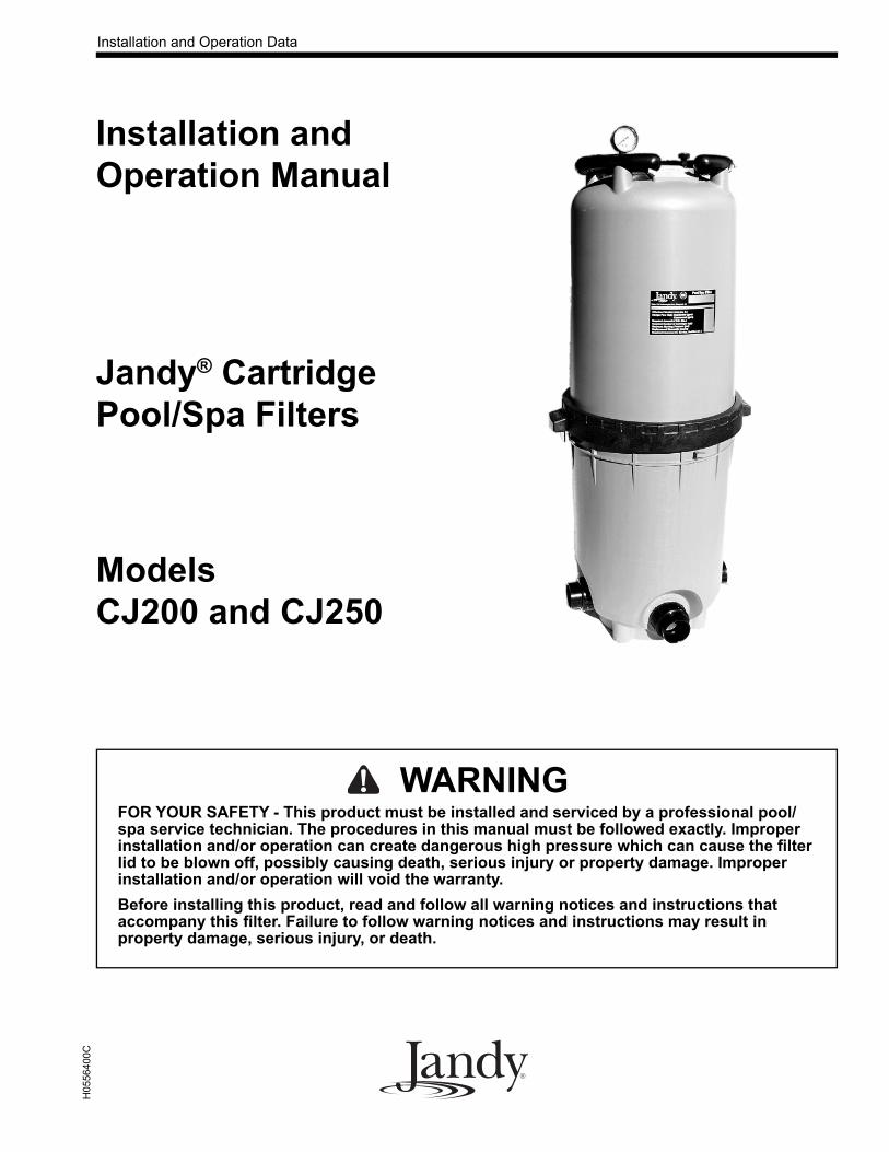
DATE OF INSTALLATION
INITIAL PRESSURE GAUGE READING (WITH CLEAN FILTER)
PUMP MODEL HORSEPOWER
FILTER MODEL SERIAL NUMBER
NOTES:
EQUIPMENT INFORMATION RECORD
TABLE OF CONTENTS
Section 1. Safety Information ........................... 4
1.1 Important Safety Warning ........... 41.2 General Safety Instructions ......... 4
Section 2. General Information......................... 5
2.1 Introduction ................................. 52.2 Description .................................. 52.3 General Requirements ............. ... 5
Section 3. Installation Instructions.................... 6
3.1 Filter Location ............................. 63.2 Filter Preparation......................... 63.3 Filter Installation ......................... 73.4 Locking Ring Installation............ 8
Section 4. Start-Up and Operation .................... 8
4.1 New Pool and Seasonal Start-up . 8
Section 5. Filter Disassembly and Assembly.... 9
5.1 Filter Element Removal .............. 95.2 Changing the Outlet Port............. 10
Section 6. Maintenance..................................... 11
6.1 General Maintenance................... 116.2 Pressure Gauge............................ 116.3 Cleaning the Filter Cartridge....... 11
Section 7. Winterizing....................................... 11
Section 8. Troubleshooting ............................... 12
Section 9. Parts List and Exploded View.......... 13
9.1 Jandy® Cartridge Filter, CJ Series 139.2 Jandy® CJ Cartridge Filter Exploded
View ........................................... 13
Section 10. Head Loss Curves........................... 14
10.1 Jandy® Cartridge Filter, CJ Series 14
Page 4
Section 1. Safety Information
1.1 Important Safety Warning
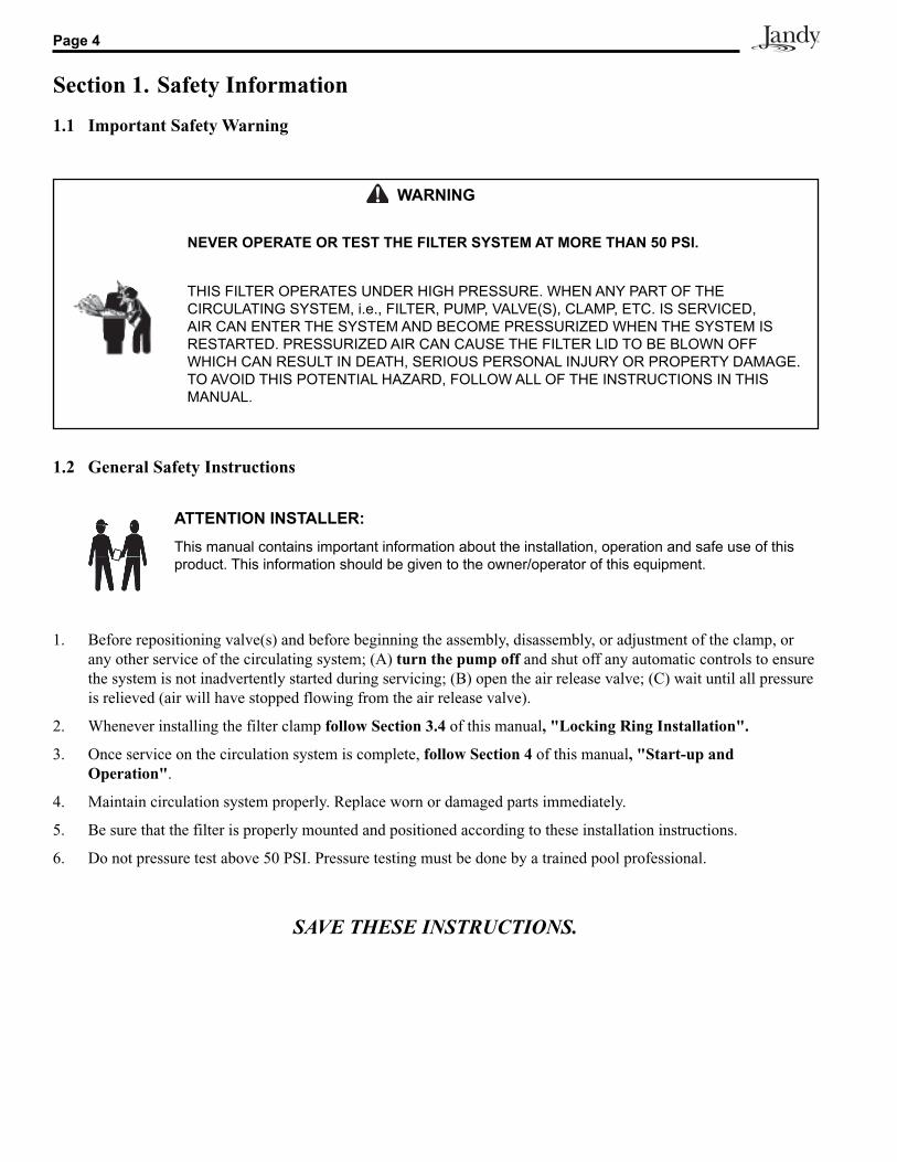
1. Before repositioning valve(s) and before beginning the assembly, disassembly, or adjustment of the clamp, or any other service of the circulating system; (A) turn the pump off and shut off any automatic controls to ensure the system is not inadvertently started during servicing; (B) open the air release valve; (C) wait until all pressure is relieved (air will have stopped flowing from the air release valve).
2. Whenever installing the filter clamp follow Section 3.4 of this manual, "Locking Ring Installation".
3. Once service on the circulation system is complete, follow Section 4 of this manual, "Start-up and Operation".
4. Maintain circulation system properly. Replace worn or damaged parts immediately.
5. Be sure that the filter is properly mounted and positioned according to these installation instructions.
6. Do not pressure test above 50 PSI. Pressure testing must be done by a trained pool professional.
SAVE THESE INSTRUCTIONS.
ATTENTION INSTALLER:This manual contains important information about the installation, operation and safe use of this product. This information should be given to the owner/operator of this equip ment.
1.2 General Safety Instructions
WARNING
NEVER OPERATE OR TEST THE FIL TER SYSTEM AT MORE THAN 50 PSI.
THIS FILTER OPERATES UNDER HIGH PRESSURE. WHEN ANY PART OF THE CIRCULATING SYSTEM, i.e., FILTER, PUMP, VALVE(S), CLAMP, ETC. IS SERVICED, AIR CAN ENTER THE SYSTEM AND BECOME PRESSURIZED WHEN THE SYSTEM IS RESTARTED. PRESSURIZED AIR CAN CAUSE THE FILTER LID TO BE BLOWN OFF WHICH CAN RESULT IN DEATH, SERIOUS PERSONAL INJURY OR PROPERTY DAMAGE. TO AVOID THIS PO TEN TIAL HAZ ARD, FOL LOW ALL OF THE IN STRUC TIONS IN THIS MAN U AL.
Page 5Cartridge Filters - CJ Series Filter
Section 2. General Information
2.1 Introduction
This manual contains information for the proper instal-lation and operation of the Jandy® CJ Cartridge Filters. Procedures in this manual must be followed exactly. To obtain additional copies of this manual contact us at 707.776.8200 ext. 237. For address information see back cover.
2.2 Description
Cartridge filters do not require sand or diatomaceous earth as the filter medium. Instead they contain a filter cartridge element which is easily removed for cleaning or replacement.
Dirty water flows into the filter tank and is directed through the filter cartridge. The debris is collected on the surface of the cartridge as the water flows through it. The water will travel through the central filter core towards the bottom of the filter into the lower manifold. Clean water is returned to the swimming pool through the filter outlet port at the tank's bottom.
As debris collects in the filter, the pressure will rise and water flow to the pool will diminish. The filter will eventually become so plugged with debris that it will be necessary to remove the filter cartridge and clean it (see Section 6 "Cleaning the Filter").
NOTE A filter removes dirt and other suspended particles but does not sanitize the pool. Pool water must be sanitized and chemically balanced for clear water. The filtration system should be designed to meet local health codes. At a minimum, the system should turnover the total volume of water in your pool two to four times in a 24 hour period.
2.3 General Requirements1. For best overall performance place the system as
close to the pool as possible.
2. The filter should be located on a level concrete slab so that the orientation of the valve outlets and the pressure gauge are convenient and accessible for the installation and operation of the unit.
3. Protect the filter from the weather.
4. If fitting a chlorinator and/or any other device into the filtration plumbing circuit, great care must be xercised to ensure that the appliance is installed in accordance with the Manufacturer’s Instructions and any standards that may exist.
5. Use barrel unions to connect each component of the water conditioning system for future servicing. All Jandy filters come with these type of fittings.
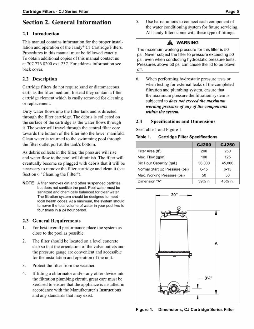
CJ200 CJ250Filter Area (ft2) 200 250Max. Flow (gpm) 100 125Six Hour Capacity (gal.) 36,000 45,000Normal Start Up Pressure (psi) 6-15 6-15Max. Working Pressure (psi) 50 50Dimension "A" 39½ in 45½ in.
Table 1. Cartridge Filter Specifi cations
WARNINGThe maximum working pressure for this filter is 50 psi. Never subject the filter to pressure exceeding 50 psi, even when conducting hydrostatic pressure tests. Pressures above 50 psi can cause the lid to be blown off.
6. When performing hydrostatic pressure tests or when testing for external leaks of the completed filtration and plumbing system, ensure that the maximum pressure the filtration system is subjected to does not exceed the maximum working pressure of any of the components within the system.
2.4 Specifications and Dimensions
See Table 1 and Figure 1.
Figure 1. Dimensions, CJ Cartridge Series Filter
A
3¼"
20"
Page 6
CAUTIONMaintain your pressure gauge in good work ing order. The pressure gauge is the primary indicator of how the filter is operating.
WARNINGWater discharged from an improperly positioned filter or valve can create an electrical hazard which can cause death, serious injury or property damage.
Section 3. Installation Instructions
3.1 Filter Location1. Select a well-drained area, one that does not flood
when it rains. Damp, non-ventilated areas should be avoided.
2. Provide solid mounting for the filter and pump system. Install system on a concrete slab or solid concrete blocks to avoid risk of settlement. Do not use sand to level the filter as the sand will wash away. Filter systems can weigh up to 300 lbs.
3. Install electrical controls at least five (5) feet from the filter. This will allow enough room to stand away from the filter during start-up.
4. Allow sufficient clearance around the filter to permit a visual inspection of the clamp ring (see Fig. 2).
5. Allow sufficient space above the filter to remove the filter lid and filter element for cleaning and servicing.
6. Position the filter to safely direct water drainage. Align the air release valve to safely direct purged air or water.
7. If the filter is to be installed below the water level of the pool, isolation valves should be installed on both the suction and return lines to prevent back flow of pool water during any routine servicing that may be required.
3.2 Filter Preparation1. Check carton for damage due to rough handling
in shipment. If carton or any filter components are damaged, notify carrier immediately.
2. Carefully remove the accessory package. Remove the filter tank from the carton.
3. A visual inspection of all parts should be made now. See parts list on page 13.
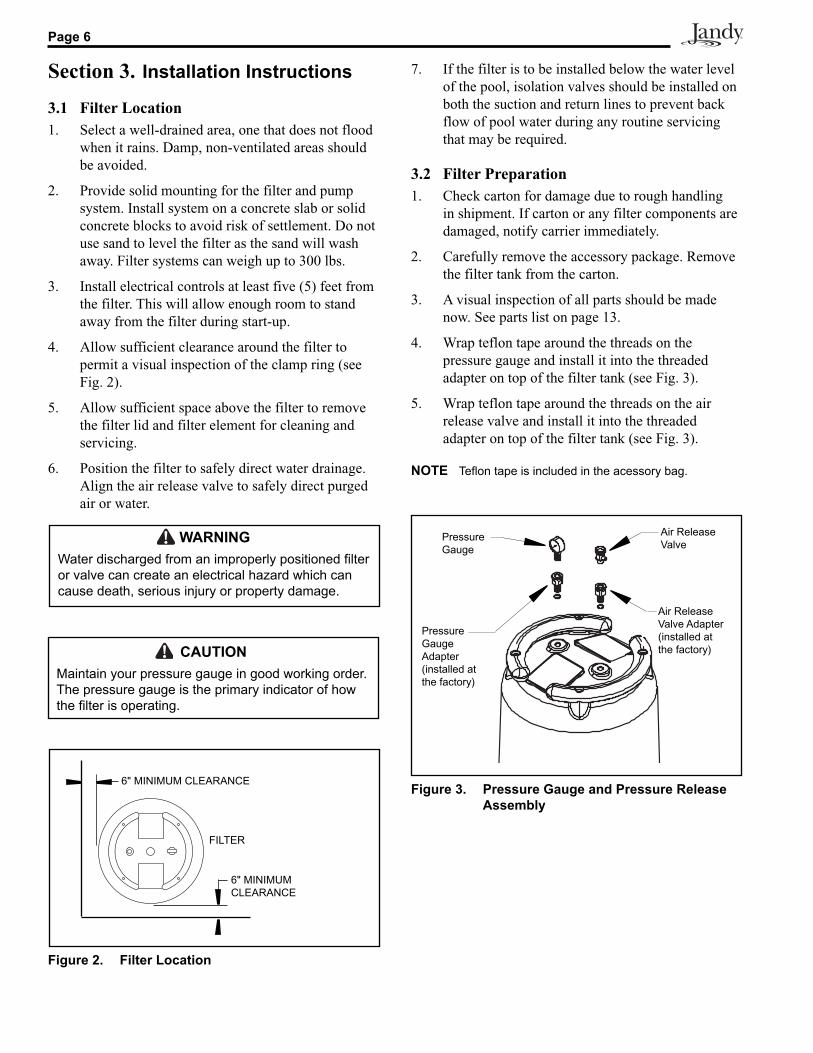
4. Wrap teflon tape around the threads on the pressure gauge and install it into the threaded adapter on top of the filter tank (see Fig. 3).
5. Wrap teflon tape around the threads on the air release valve and install it into the threaded adapter on top of the filter tank (see Fig. 3).
NOTE Teflon tape is included in the acessory bag.
Figure 2. Filter Location
FILTER
6" MINIMUM CLEARANCE
6" MINIMUM CLEARANCE Figure 3. Pressure Gauge and Pressure Release Assembly
Air Release Valve
Pressure Gauge
Pressure Gauge Adapter(installed at the factory)
Air Release Valve Adapter(installed at the factory)
Page 7Cartridge Filters - CJ Series Filter
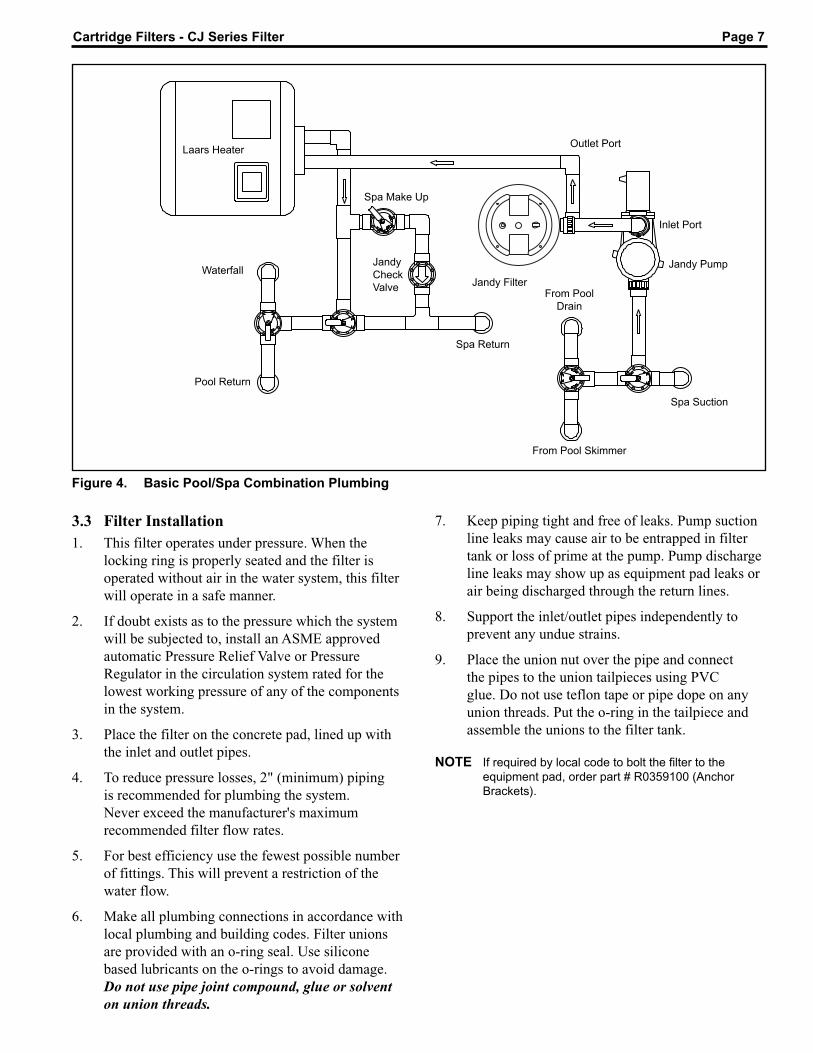
Figure 4. Basic Pool/Spa Combination Plumbing
Laars Heater
Waterfall
Pool Return
Spa Make Up
Spa Return
From Pool Skimmer
From Pool Drain
Spa Suction
Jandy PumpJandyCheckValve
Outlet Port
Inlet Port
Jandy Filter
7. Keep piping tight and free of leaks. Pump suction line leaks may cause air to be entrapped in filter tank or loss of prime at the pump. Pump discharge line leaks may show up as equipment pad leaks or air being discharged through the return lines.
8. Support the inlet/outlet pipes independently to prevent any undue strains.
9. Place the union nut over the pipe and connect the pipes to the union tailpieces using PVC glue. Do not use teflon tape or pipe dope on any union threads. Put the o-ring in the tailpiece and assemble the unions to the filter tank.
NOTE If required by local code to bolt the filter to the equipment pad, order part # R0359100 (Anchor Brackets).
3.3 Filter Installation1. This filter operates under pressure. When the
locking ring is properly seated and the filter is operated without air in the water system, this filter will operate in a safe manner.
2. If doubt exists as to the pressure which the system will be subjected to, install an ASME approved automatic Pressure Relief Valve or Pressure Regulator in the circulation system rated for the lowest working pressure of any of the components in the system.
3. Place the filter on the concrete pad, lined up with the inlet and outlet pipes.
4. To reduce pressure losses, 2" (minimum) piping is recommended for plumbing the system. Never exceed the manufacturer's maximum recommended filter flow rates.
5. For best efficiency use the fewest possible number of fittings. This will prevent a restriction of the water flow.
6. Make all plumbing connections in accordance with local plumbing and building codes. Filter unions are provided with an o-ring seal. Use silicone based lubricants on the o-rings to avoid damage. Do not use pipe joint compound, glue or solvent on union threads.
Page 8
Tabs
WARNINGFollow these instructions carefully. Improper locking ring installation can cause the filter lid to be blown off which can result in death, serious personal injury or property dam age.
WARNINGNEVER operate the filter system at more than 50 psi of pressure. Operating the filter system in excess of 50 psi can cause the filter lid to be blown off, which can cause death, serious personal injury or property damage.
CautionDO NOT operate filter at water temperatures above 120° F (65.5° C). Water temperatures above the manufacturer's recommendations will shorten the life span of the filter and void the warranty.
WARNINGNEVER start pump while standing within five (5) feet of the filter. Starting the pump while there is pressurized air in the system can cause the filter lid to be blown off, which can cause death, se ri ous personal injury or property damage.
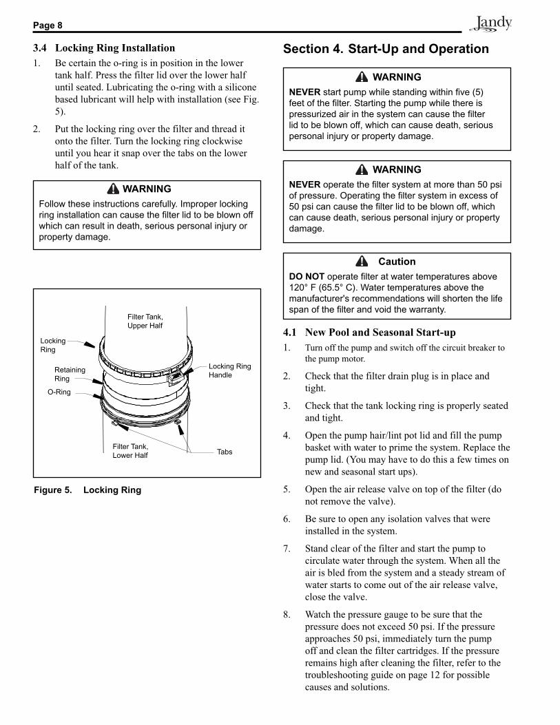
3.4 Locking Ring Installation1. Be certain the o-ring is in position in the lower
tank half. Press the filter lid over the lower half until seated. Lubricating the o-ring with a silicone based lubricant will help with installation (see Fig. 5).
2. Put the locking ring over the filter and thread it onto the filter. Turn the locking ring clockwise until you hear it snap over the tabs on the lower half of the tank.
Section 4. Start-Up and Operation
4.1 New Pool and Seasonal Start-up1. Turn off the pump and switch off the circuit breaker to
the pump motor.
2. Check that the filter drain plug is in place and tight.
3. Check that the tank locking ring is properly seated and tight.
4. Open the pump hair/lint pot lid and fill the pump basket with water to prime the system. Replace the pump lid. (You may have to do this a few times on new and seasonal start ups).
5. Open the air release valve on top of the filter (do not remove the valve).
6. Be sure to open any isolation valves that were installed in the system.
7. Stand clear of the filter and start the pump to circulate water through the system. When all the air is bled from the system and a steady stream of water starts to come out of the air release valve, close the valve.
8. Watch the pressure gauge to be sure that the pressure does not exceed 50 psi. If the pressure approaches 50 psi, immediately turn the pump off and clean the filter cartridges. If the pressure remains high after cleaning the filter, refer to the troubleshooting guide on page 12 for possible causes and solutions.
Figure 5. Locking Ring
Filter Tank, Lower Half
Filter Tank, Upper Half
Locking Ring
Locking Ring Handle
O-Ring
RetainingRing
Page 9Cartridge Filters - CJ Series Filter
Section 5. Filter Disassembly and Assembly
WARNINGNEVER attempt to assemble, dis as sem ble or adjust the filter when there is pressurized air in the system. Starting the pump while there is any pressurized air in the system can cause the filter lid to be blown off, which can cause death, serious personal injury or property dam age.
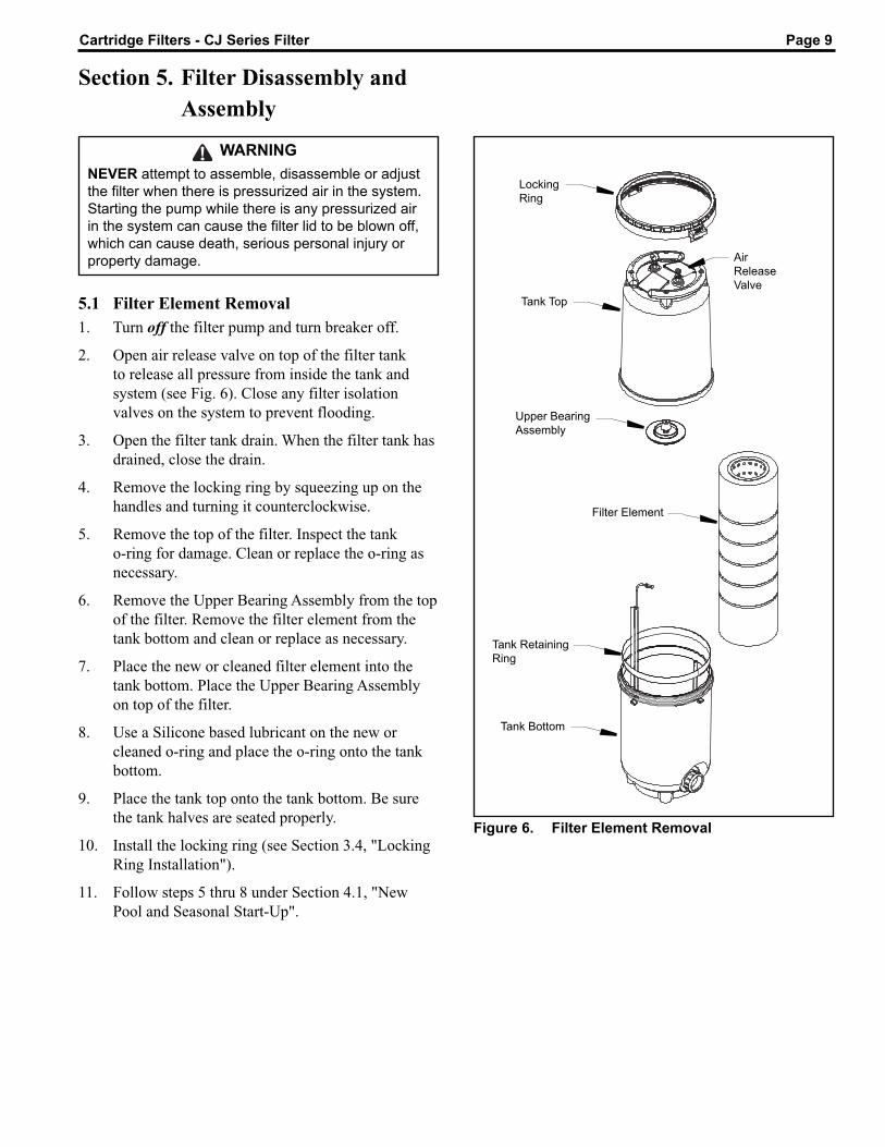
5.1 Filter Element Removal1. Turn off the filter pump and turn breaker off.
2. Open air release valve on top of the filter tank to release all pressure from inside the tank and system (see Fig. 6). Close any filter isolation valves on the system to prevent flooding.
3. Open the filter tank drain. When the filter tank has drained, close the drain.
4. Remove the locking ring by squeezing up on the handles and turning it counterclockwise.
5. Remove the top of the filter. Inspect the tank o-ring for damage. Clean or replace the o-ring as necessary.
6. Remove the Upper Bearing Assembly from the top of the filter. Remove the filter element from the tank bottom and clean or replace as necessary.
7. Place the new or cleaned filter element into the tank bottom. Place the Upper Bearing Assembly on top of the filter.
8. Use a Silicone based lubricant on the new or cleaned o-ring and place the o-ring onto the tank bottom.
9. Place the tank top onto the tank bottom. Be sure the tank halves are seated properly.
10. Install the locking ring (see Section 3.4, "Locking Ring Installation").
11. Follow steps 5 thru 8 under Section 4.1, "New Pool and Seasonal Start-Up".
Figure 6. Filter Element Removal
Locking Ring
Tank Top
Upper Bearing Assembly
Filter Element
Tank Bottom
Air Release Valve
Tank Retaining Ring
Page 10
5.2 Changing the Outlet Port1. Follow steps 1 thru 6 under Section 5.1, "Filter
Element Removal".
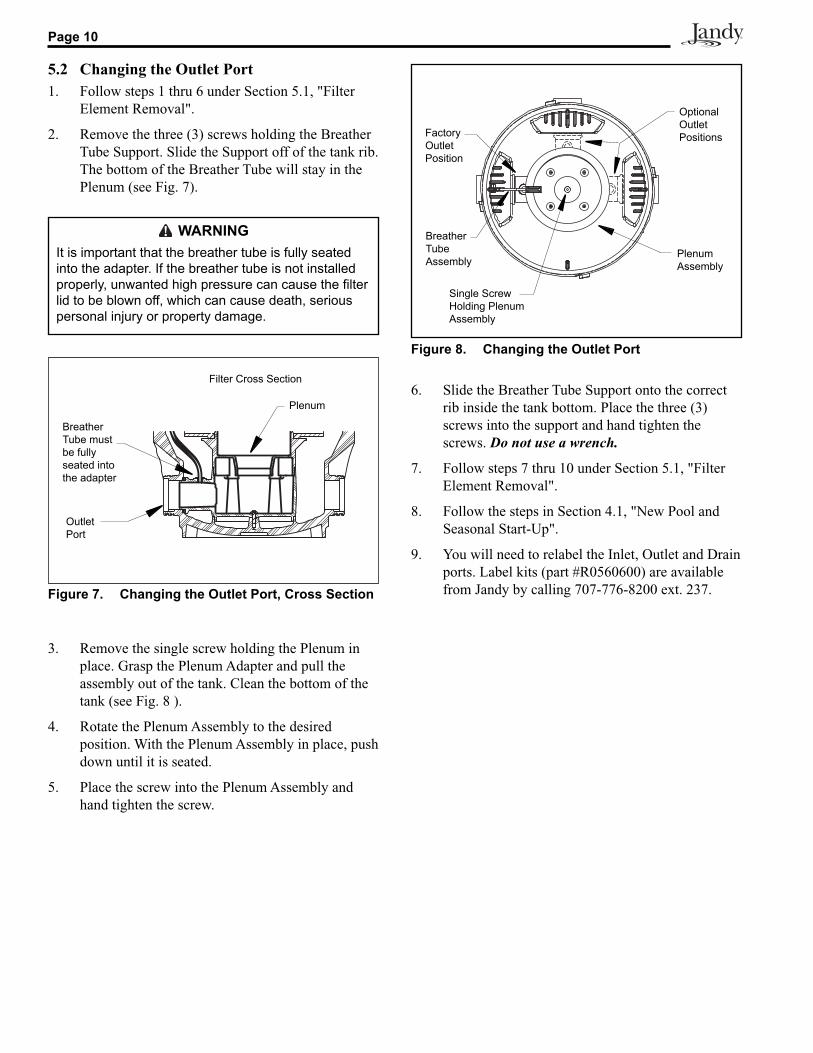
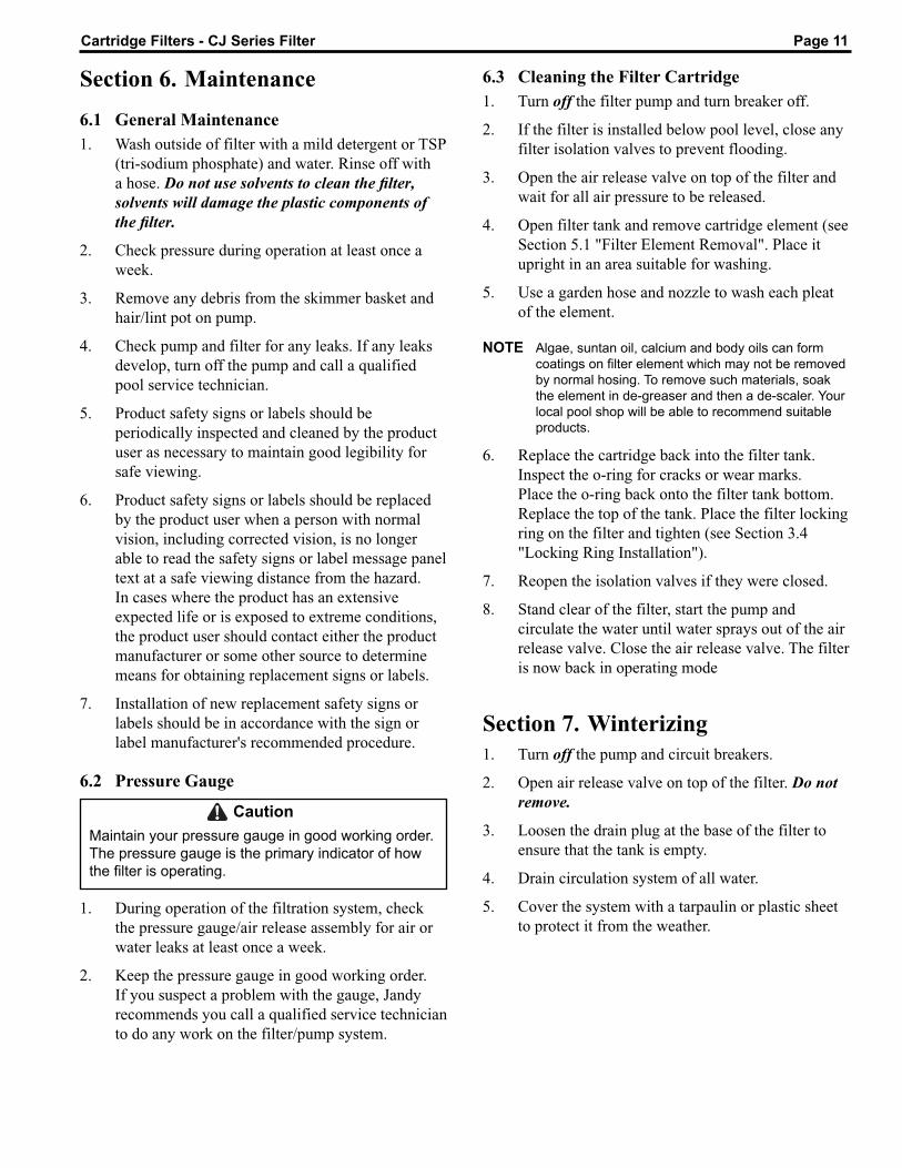
2. Remove the three (3) screws holding the Breather Tube Support. Slide the Support off of the tank rib. The bottom of the Breather Tube will stay in the Plenum (see Fig. 7).
3. Remove the single screw holding the Plenum in place. Grasp the Plenum Adapter and pull the assembly out of the tank. Clean the bottom of the tank (see Fig. 8 ).
4. Rotate the Plenum Assembly to the desired position. With the Plenum Assembly in place, push down until it is seated.
5. Place the screw into the Plenum Assembly and hand tighten the screw.
6. Slide the Breather Tube Support onto the correct rib inside the tank bottom. Place the three (3) screws into the support and hand tighten the screws. Do not use a wrench.
7. Follow steps 7 thru 10 under Section 5.1, "Filter Element Removal".
8. Follow the steps in Section 4.1, "New Pool and Seasonal Start-Up".
9. You will need to relabel the Inlet, Outlet and Drain ports. Label kits (part #R0560600) are available from Jandy by calling 707-776-8200 ext. 237.
WARNINGIt is important that the breather tube is fully seated into the adapter. If the breather tube is not in stalled properly, unwanted high pressure can cause the filter lid to be blown off, which can cause death, serious personal injury or prop er ty damage.
Figure 7. Changing the Outlet Port, Cross Section
Breather Tube must be fully seated into the adapter
Outlet Port
Filter Cross Section
Plenum
Figure 8. Changing the Outlet Port
Factory Outlet Position
Plenum Assembly
Optional Outlet Positions
Breather Tube Assembly
Single Screw Holding Plenum Assembly
Page 11Cartridge Filters - CJ Series Filter
Section 6. Maintenance
6.1 General Maintenance1. Wash outside of filter with a mild detergent or TSP
(tri-sodium phosphate) and water. Rinse off with a hose. Do not use solvents to clean the fi lter, solvents will damage the plastic components of the fi lter.
2. Check pressure during operation at least once a week.
3. Remove any debris from the skimmer basket and hair/lint pot on pump.
4. Check pump and filter for any leaks. If any leaks develop, turn off the pump and call a qualified pool service technician.
5. Product safety signs or labels should be periodically inspected and cleaned by the product user as necessary to maintain good legibility for safe viewing.
6. Product safety signs or labels should be replaced by the product user when a person with normal vision, including corrected vision, is no longer able to read the safety signs or label message panel text at a safe viewing distance from the hazard. In cases where the product has an extensive expected life or is exposed to extreme conditions, the product user should contact either the product manufacturer or some other source to determine means for obtaining replacement signs or labels.
7. Installation of new replacement safety signs or labels should be in accordance with the sign or label manufacturer's recommended procedure.
6.2 Pressure Gauge
CautionMaintain your pressure gauge in good working order. The pressure gauge is the primary indicator of how the filter is operating.
1. During operation of the filtration system, check the pressure gauge/air release assembly for air or water leaks at least once a week.
2. Keep the pressure gauge in good working order. If you suspect a problem with the gauge, Jandy recommends you call a qualified service technician to do any work on the filter/pump system.
6.3 Cleaning the Filter Cartridge1. Turn off the filter pump and turn breaker off.
2. If the filter is installed below pool level, close any filter isolation valves to prevent flooding.
3. Open the air release valve on top of the filter and wait for all air pressure to be released.
4. Open filter tank and remove cartridge element (see Section 5.1 "Filter Element Removal". Place it upright in an area suitable for washing.
5. Use a garden hose and nozzle to wash each pleat of the element.
NOTE Algae, suntan oil, calcium and body oils can form coatings on filter element which may not be removed by normal hosing. To remove such materials, soak the element in de-greaser and then a de-scaler. Your local pool shop will be able to recommend suitable products.
6. Replace the cartridge back into the filter tank. Inspect the o-ring for cracks or wear marks. Place the o-ring back onto the filter tank bottom. Replace the top of the tank. Place the filter locking ring on the filter and tighten (see Section 3.4 "Locking Ring Installation").
7. Reopen the isolation valves if they were closed.
8. Stand clear of the filter, start the pump and circulate the water until water sprays out of the air release valve. Close the air release valve. The filter is now back in operating mode
Section 7. Winterizing1. Turn off the pump and circuit breakers.
2. Open air release valve on top of the filter. Do not remove.
3. Loosen the drain plug at the base of the filter to ensure that the tank is empty.
4. Drain circulation system of all water.
5. Cover the system with a tarpaulin or plastic sheet to protect it from the weather.
Page 12
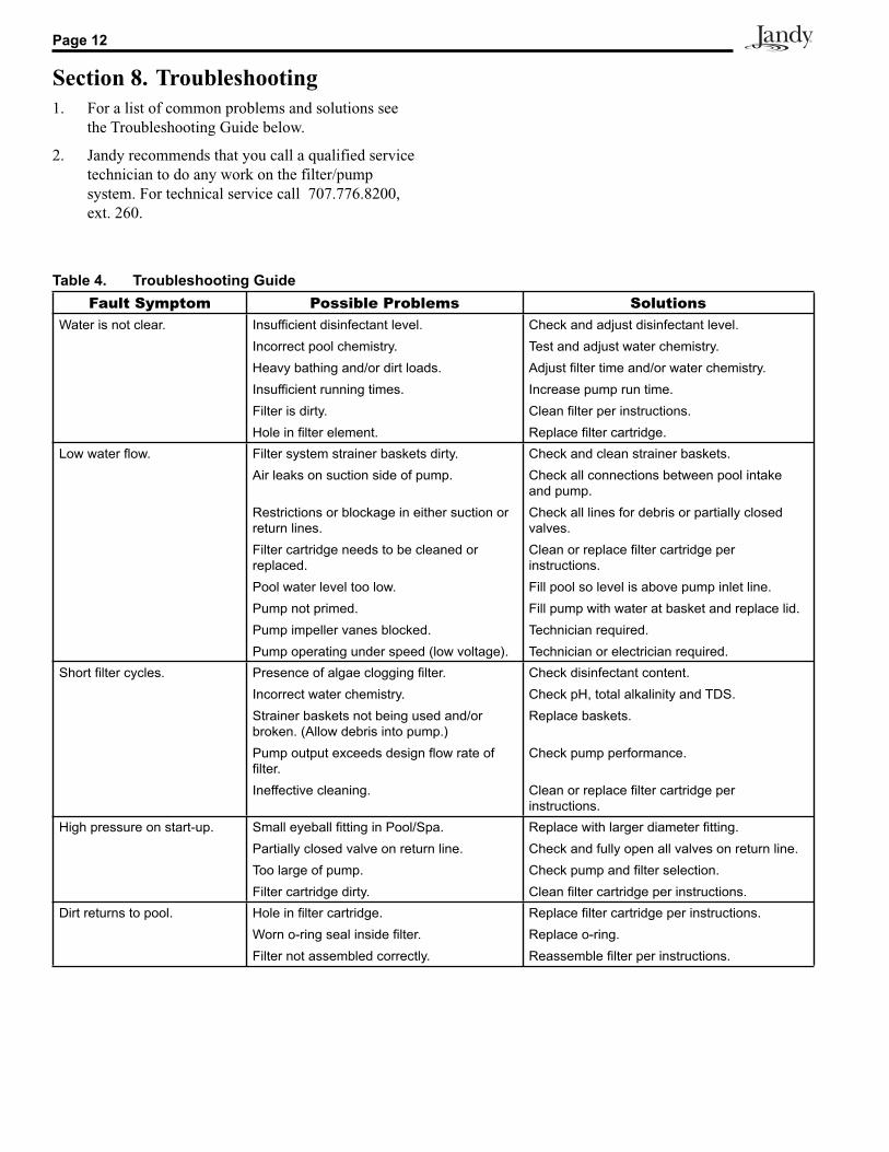
Section 8. Troubleshooting1. For a list of common problems and solutions see
the Troubleshooting Guide below.
2. Jandy recommends that you call a qualified service technician to do any work on the filter/pump system. For technical service call 707.776.8200, ext. 260.
Table 4. Troubleshooting GuideFault Symptom Possible Problems Solutions
Water is not clear. Insufficient disinfectant level.Incorrect pool chemistry.Heavy bathing and/or dirt loads.Insufficient running times.Filter is dirty.Hole in filter element.
Check and adjust disinfectant level.Test and adjust water chemistry.Adjust filter time and/or water chemistry.Increase pump run time.Clean filter per instructions.Replace filter cartridge.
Low water flow. Filter system strainer baskets dirty.Air leaks on suction side of pump.
Restrictions or blockage in either suction or return lines.Filter cartridge needs to be cleaned or replaced. Pool water level too low.Pump not primed.Pump impeller vanes blocked.Pump operating under speed (low voltage).
Check and clean strainer baskets.Check all connections between pool intake and pump.Check all lines for debris or partially closed valves.Clean or replace filter cartridge per instructions.Fill pool so level is above pump inlet line.Fill pump with water at basket and replace lid.Technician required.Technician or electrician required.
Short filter cycles. Presence of algae clogging filter.Incorrect water chemistry.Strainer baskets not being used and/or broken. (Allow debris into pump.)Pump output exceeds design flow rate of filter.Ineffective cleaning.
Check disinfectant content.Check pH, total alkalinity and TDS.Replace baskets.
Check pump performance.
Clean or replace filter cartridge per in struc tions.
High pressure on start-up. Small eyeball fitting in Pool/Spa.Partially closed valve on return line.Too large of pump.Filter cartridge dirty.
Replace with larger diameter fitting.Check and fully open all valves on return line.Check pump and filter selection.Clean filter cartridge per instructions.
Dirt returns to pool. Hole in filter cartridge.Worn o-ring seal inside filter.Filter not assembled correctly.
Replace filter cartridge per instructions.Replace o-ring.Reassemble filter per instructions.
Page 13Cartridge Filters - CJ Series Filter
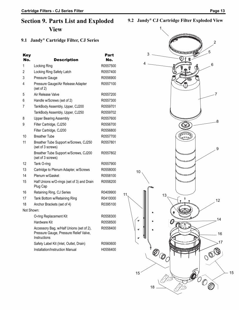
Key No. Description
Part No.
1 Locking Ring R05575002 Locking Ring Safety Latch R05574003 Pressure Gauge R05569004 Pressure Gauge/Air Release Adapter
(set of 2)R0557100
5 Air Release Valve R05572006 Handle w/Screws (set of 2) R05573007 TankBody Assembly, Upper, CJ200 R0559701
TankBody Assembly, Upper, CJ250 R05597028 Upper Bearing Assembly R05576009 Filter Cartridge, CJ250 R0556700
Filter Cartridge, CJ200 R055680010 Breather Tube R055770011 Breather Tube Support w/Screws, CJ250
(set of 3 screws)R0557801
Breather Tube Support w/Screws, CJ200(set of 3 screws)
R0557802
12 Tank O-ring R055790013 Cartridge to Plenum Adapter, w/Screws R055800014 Plenum w/Gasket R055810015 Half Unions w/O-rings (set of 3) and Drain
Plug CapR0558200
16 Retaining Ring, CJ Series R040990017 Tank Bottom w/Retaining Ring R041000018 Anchor Brackets (set of 4) R0395100Not Shown:
O-ring Replacement Kit R0558300Hardware Kit R0558500Accessory Bag, w/Half Unions (set of 2), Pressure Gauge, Pressure Relief Valve, Instructions
R0558400
Safety Label Kit (Inlet, Outlet, Drain) R0560600Installation/Instruction Manual H0556400
Section 9. Parts List and Exploded View
9.1 Jandy® Cartridge Filter, CJ Series
9.2 Jandy® CJ Cartridge Filter Exploded View
2
6
5
7
8
10
17
3
12
9
1
4
11
14
18
13
15 15
16
Page 14
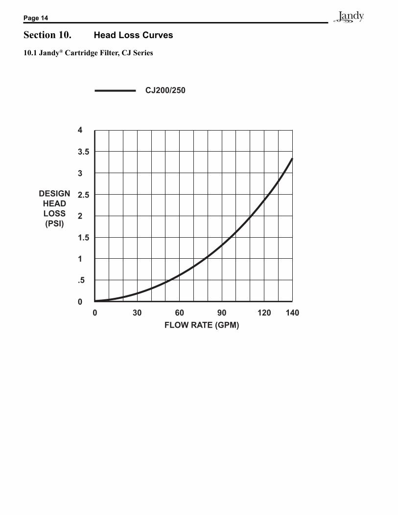
Section 10. Head Loss Curves
10.1 Jandy® Cartridge Filter, CJ Series

Page 15Cartridge Filters - CJ Series Filter
NOTES
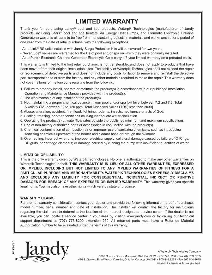
LIMITED WARRANTYThank you for purchasing Jandy® pool and spa products. Waterpik Technologies (manufacturer of Jandyproducts, including Laars® pool and spa heaters, Air Energy Heat Pumps, and Clormatic Electronic ChlorineGenerators) warrants all parts to be free from manufacturing defects in materials and workmanship for a period ofone year from the date of retail purchase, with the following exceptions:
• AquaLink® RS units installed with Jandy Surge Protection Kits will be covered for two years.• NeverLube® valves are warranted for the life of pool and/or spa on which they were originally installed.• AquaPureTM Electronic Chlorine Generator Electrolytic Cells carry a 5 year limited warranty on a prorated basis.
This warranty is limited to the first retail purchaser, is not transferable, and does not apply to products that havebeen moved from their original installation sites. The liability of Waterpik Technologies shall not exceed the repairor replacement of defective parts and does not include any costs for labor to remove and reinstall the defectivepart, transportation to or from the factory, and any other materials required to make the repair. This warranty doesnot cover failures or malfunctions resulting from the following:
1. Failure to properly install, operate or maintain the product(s) in accordance with our published Installation,Operation and Maintenance Manuals provided with the product(s).
2. The workmanship of any installer of the product(s).3. Not maintaining a proper chemical balance in your pool and/or spa [pH level between 7.2 and 7.8, Total
Alkalinity (TA) between 80 to 120 ppm, Total Dissolved Solids (TDS) less than 2000].4. Abuse, alteration, accident, fire, flood, lightning, rodents, insects, negligence or acts of God.5. Scaling, freezing, or other conditions causing inadequate water circulation.6. Operating the product(s) at water flow rates outside the published minimum and maximum specifications.7. Use of non-factory authorized parts or accessories in conjunction with the product(s).8. Chemical contamination of combustion air or improper use of sanitizing chemicals, such as introducing
sanitizing chemicals upstream of the heater and cleaner hose or through the skimmer.9. Overheating, incorrect wire runs; improper electrical supply; collateral damage caused by failure of O-Rings,
DE grids, or cartridge elements; or damage caused by running the pump with insufficient quantities of water.
LIMITATION OF LIABILITY:This is the only warranty given by Waterpik Technologies. No one is authorized to make any other warranties onWaterpik Technologies' behalf. THIS WARRANTY IS IN LIEU OF ALL OTHER WARRANTIES, EXPRESSEDOR IMPLIED, INCLUDING BUT NOT LIMITED TO ANY IMPLIED WARRANTIES OF FITNESS FOR APARTICULAR PURPOSE AND MERCHANTABILITY. WATERPIK TECHNOLOGIES EXPRESSLY DISCLAIMSAND EXCLUDES ANY LIABILITY FOR CONSEQUENTIAL, INCIDENTAL, INDIRECT OR PUNITIVEDAMAGES FOR BREACH OF ANY EXPRESSED OR IMPLIED WARRANTY. This warranty gives you specificlegal rights. You may also have other rights which vary by state or province.
WARRANTY CLAIMS:For prompt warranty consideration, contact your dealer and provide the following information: proof of purchase,model number, serial number and date of installation. The installer will contact the factory for instructionsregarding the claim and to determine the location of the nearest designated service center. If the dealer is notavailable, you can locate a service center in your area by visiting www.jandy.com or by calling our technicalsupport department at (707) 776-8200 extension 260. All returned parts must have a Returned MaterialAuthorization number to be evaluated under the terms of this warranty.
6000 Condor Drive • Moorpark, CA USA 93021480 S. Service Road West • Oakville, Ontario, Canada L6K 2H4
A Waterpik Technologies Company
• 707.776.8200 • Fax 707.763.7785• 905.844.8233 • Fax 905.844.2635Litho in U.S.A. © Waterpik Technologies 0406
H05
5640
0C